EP1705297A1 - Armature sanitaire avec tuyau d'écoulement gidant la lumière - Google Patents
Armature sanitaire avec tuyau d'écoulement gidant la lumière Download PDFInfo
- Publication number
- EP1705297A1 EP1705297A1 EP05005389A EP05005389A EP1705297A1 EP 1705297 A1 EP1705297 A1 EP 1705297A1 EP 05005389 A EP05005389 A EP 05005389A EP 05005389 A EP05005389 A EP 05005389A EP 1705297 A1 EP1705297 A1 EP 1705297A1
- Authority
- EP
- European Patent Office
- Prior art keywords
- sanitary fitting
- water
- fitting according
- housing
- light
- Prior art date
- Legal status (The legal status is an assumption and is not a legal conclusion. Google has not performed a legal analysis and makes no representation as to the accuracy of the status listed.)
- Granted
Links
- XLYOFNOQVPJJNP-UHFFFAOYSA-N water Substances O XLYOFNOQVPJJNP-UHFFFAOYSA-N 0.000 claims abstract description 48
- 238000011144 upstream manufacturing Methods 0.000 claims abstract description 8
- 230000008878 coupling Effects 0.000 claims description 13
- 238000010168 coupling process Methods 0.000 claims description 13
- 238000005859 coupling reaction Methods 0.000 claims description 13
- 230000005611 electricity Effects 0.000 claims 1
- 239000008400 supply water Substances 0.000 claims 1
- 239000012780 transparent material Substances 0.000 claims 1
- 239000011324 bead Substances 0.000 description 9
- 230000005540 biological transmission Effects 0.000 description 8
- 239000000523 sample Substances 0.000 description 5
- 239000000463 material Substances 0.000 description 4
- 238000007789 sealing Methods 0.000 description 4
- 239000002184 metal Substances 0.000 description 3
- 230000003287 optical effect Effects 0.000 description 3
- 230000001681 protective effect Effects 0.000 description 3
- 238000005266 casting Methods 0.000 description 2
- 239000012528 membrane Substances 0.000 description 2
- 239000004033 plastic Substances 0.000 description 2
- 229920003023 plastic Polymers 0.000 description 2
- 229920003229 poly(methyl methacrylate) Polymers 0.000 description 2
- 239000004926 polymethyl methacrylate Substances 0.000 description 2
- 239000011347 resin Substances 0.000 description 2
- 229920005989 resin Polymers 0.000 description 2
- 230000007704 transition Effects 0.000 description 2
- 238000005276 aerator Methods 0.000 description 1
- 238000004140 cleaning Methods 0.000 description 1
- 238000004040 coloring Methods 0.000 description 1
- 150000001875 compounds Chemical class 0.000 description 1
- 230000007423 decrease Effects 0.000 description 1
- 230000003111 delayed effect Effects 0.000 description 1
- 230000001419 dependent effect Effects 0.000 description 1
- 238000000605 extraction Methods 0.000 description 1
- 239000000945 filler Substances 0.000 description 1
- 239000011521 glass Substances 0.000 description 1
- 238000002347 injection Methods 0.000 description 1
- 239000007924 injection Substances 0.000 description 1
- 230000013011 mating Effects 0.000 description 1
- 238000000034 method Methods 0.000 description 1
- 238000007788 roughening Methods 0.000 description 1
Images


Classifications
-
- E—FIXED CONSTRUCTIONS
- E03—WATER SUPPLY; SEWERAGE
- E03C—DOMESTIC PLUMBING INSTALLATIONS FOR FRESH WATER OR WASTE WATER; SINKS
- E03C1/00—Domestic plumbing installations for fresh water or waste water; Sinks
- E03C1/02—Plumbing installations for fresh water
- E03C1/04—Water-basin installations specially adapted to wash-basins or baths
- E03C1/0404—Constructional or functional features of the spout
-
- F—MECHANICAL ENGINEERING; LIGHTING; HEATING; WEAPONS; BLASTING
- F21—LIGHTING
- F21V—FUNCTIONAL FEATURES OR DETAILS OF LIGHTING DEVICES OR SYSTEMS THEREOF; STRUCTURAL COMBINATIONS OF LIGHTING DEVICES WITH OTHER ARTICLES, NOT OTHERWISE PROVIDED FOR
- F21V33/00—Structural combinations of lighting devices with other articles, not otherwise provided for
- F21V33/0004—Personal or domestic articles
- F21V33/004—Sanitary equipment, e.g. mirrors, showers, toilet seats or paper dispensers
-
- F—MECHANICAL ENGINEERING; LIGHTING; HEATING; WEAPONS; BLASTING
- F21—LIGHTING
- F21Y—INDEXING SCHEME ASSOCIATED WITH SUBCLASSES F21K, F21L, F21S and F21V, RELATING TO THE FORM OR THE KIND OF THE LIGHT SOURCES OR OF THE COLOUR OF THE LIGHT EMITTED
- F21Y2115/00—Light-generating elements of semiconductor light sources
- F21Y2115/10—Light-emitting diodes [LED]
Definitions
- the present invention relates to a fitting according to the preamble of claim 1,
- EP-A-0 446 365 discloses a sanitary fitting with a metal discharge pipe.
- the spout has an exposed end face at a downstream end.
- a light-conducting element Through the wall of the discharge tube extends a light-conducting element, which has a coupling surface located in the end face. Light from a light source arranged in the sanitary fitting is coupled out by the light-guiding element at the coupling-out surface in such a way that a water jet is illuminated from outside through the light-conducting element.
- the sanitary fitting having a discharge pipe made of metal, light from a light source is coupled into the running out of the sanitary fitting water,
- the sanitary fitting has a arranged in a wall of the spout light guide, which ends in the flow direction above the end face.
- An end region of the light guide facing away from the light source is oriented in the direction of a flow channel and adjoins the flow channel. The light is coupled from the light guide into the outflowing water.
- DE-U-201 02 857 discloses a water jet illuminator with a jet former firmly connected to a conventional household faucet.
- the effluent from the household faucet water is illuminated by means of a light emitting diode and a light guide, one end of which rests against the light emitting diode and the other end is disposed within the outflowing water.
- the present invention has for its object to provide a generic sanitary fitting that allows a much simpler design.
- the water-guiding outflow pipe is made of a transparent, transparent or translucent material and light is coupled into the outflow pipe in the case of an upstream coupling-in surface.
- the spout has a downstream, exposed end face at which the light is extracted from the spout.
- the sanitary fitting according to the invention also makes it possible to achieve optical effects by partially exposing the lateral surface of the outflow tube.
- the sanitary fitting according to the invention has a pull-out tube which can be pulled out of a guide tube and has a water outflow head with an outflow tube attached to its end. This makes it possible to bring the Wasserauspoundkopf and thus the light source in an advantageous for cleaning an object position.
- the sanitary fitting according to the invention has the further advantage in comparison to the prior art that an environment of the outflowing water and / or the outflowing water itself can be illuminated depending on the embodiment of the end face. By illuminating the environment of the outflowing water can be ensured that even in bad ambient lighting, an object to be cleaned is optimally illuminated.
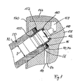
- the sanitary fitting 10 has a fitting housing 12, from which a mounting socket 14 protrudes downwards. This is intended to be the Sanitary fitting 10 to attach to a mounting surface, not shown, a washstand by means of a nut 14 '.
- the fitting housing 12 has a recess with a mixing cartridge 15 used in a known manner therein with actuating element 16 for controlling the flow of water. From the fitting housing 12 is in the vertical direction from a pivotable about a vertical axis guide tube 18 from. from the fitting housing 12 forth, the guide tube 18 tapers bell-like to a diameter D and initially runs straight and then almost in a semicircular arc. A free end portion 20 of the guide tube 18 widens bell-like and steady. The interior of the free end region 20 forms a receptacle 22 for a removable and reusable water spill head 24.
- the Wasserausmannkopf 24 is firmly connected to a through the interior of the guide tube 18, the fitting housing 12 and the mounting sleeve 14 extending through Ausziehschlauch 26.
- the Ausziehschlauch 26 runs as generally known in a loop back to the fitting housing 12.
- the Ausziehschlauch 26 has (see Fig. 2) an outer jacket hose 86 and disposed in the interior of the jacket hose 86 water hose 28. Between the jacket tube 86 and the water hose 28, an electrical line 84, preferably a multi-core stranded wire, is arranged.
- the water hose 28 is intended to guide mixed water from the mixing cartridge 15 to the water outflow head 24.
- the mixing cartridge 15 is also connected in a known manner with not shown cold and hot water supply line.
- the housing 36 has a pin-like extraction aid 38, which projects in the radial direction.
- the free end region 20 of the guide tube 18 has (see FIG. 4) a guide slot 40 which is open at the end of the guide tube 18 and through which the extension aid 38 is guided during retraction and extension of the water outflow head 24.
- the housing 36 further includes a bead 42 which, if the Wasserausmannkopf 24 is inserted into the receptacle 22 engages in the guide slot 40.
- the housing 36 is thin-walled, formed with a substantially constant wall thickness.
- the housing 36 has a circumferential housing end face 46, wherein the bead 42 projects beyond the housing end face 46 in the flow direction.
- the Wasserausmannkopf 24 has a water-conducting, rotationally symmetrical, translucent, light-conducting and connected to the water hose 28 spout 50.
- the spout 50 is made of, for example, acrylic glass or other transparent or translucent material.
- the spout 50 has a hollow cylindrical light transmission area 52 in a downstream portion. This light transmission region 52 is bounded on the one hand, upstream of a coupling surface 56 and on the other hand, at the downstream end of the light transmission region 52 and at the same time of the outflow tube 50 from an exposed end face 58.
- the end face 58 is in the outflow direction of Einkopplungs constitutional 56 and the end face 58 as well as the coupling surface 56 are perpendicular to the axis of rotation of the outflow pipe 50th
- the outflow pipe 50 has, spaced from the end face 58, a radially outer, upstream aligned shoulder 60, which bears against the housing end face 46 when the discharge pipe 50 is inserted into the housing 36. Between the shoulder 60 and the end face 58, the outflow tube 50 has an exposed lateral surface 72, wherein the exposed lateral surface 72 continuously merges continuously into an outer surface of the housing 36. The exposed lateral surface 72 is also exposed when inserted into the receptacle 22 Wasserausmannkopf 24.
- the outflow tube 50 Adjacent to the light transmission region 52, the outflow tube 50 has a connection area 64 in the vicinity of the nozzle, wherein the outflow tube 50 tapers in the transition region from the light transmission region 52 to the connection region 64.
- An inner diameter of the outflow tube tapers in two stages from the larger inner diameter of the light transmission region 52 to the smaller inner diameter of the connection region 64, wherein the inner diameter is selected such that a jet regulator 110 described below can be inserted into the outflow tube 50.
- a light source 70 is arranged directly adjacent to the coupling surface 56 of the outflow pipe 50.
- the coupled at the coupling surface 56 light of the light source 70 is transmitted through the light transmission region 52 to the end face 58 and at least this partially decoupled from the spout 50.
- the light is also coupled out of the outflow tube 50 in the area of the exposed lateral surface 72 between the shoulder 60 and the end face 58, except in the region of the bead 42.
- a light source 70 a plurality of, preferably nine light-emitting diodes (LED) 74 are used, wherein the diodes 74 are arranged in the circumferential direction at regular intervals and a light cone axis of each diode 74 at least approximately at right angles through the coupling surface 56 and parallel to the axis of rotation of the spout 50 extends ,
- the alignment of the light cone axes ensures that the largest possible proportion of the light emitted by the diodes 74 exits through the end face 58 and through the lateral surface 72.
- the light source 70 can also emit colored light.
- the diodes 74 are arranged on an annular printed circuit board 76, which surrounds the outflow pipe 50 in the connection region 64.
- a control circuit for the light source 70 is arranged with a switching element 80.
- the further printed circuit board 78 is fastened to the connecting region 64 of the outflow tube 50 and in the flow direction above the annular printed circuit board 76.
- the switching element 80 is a button 80 'with probe 82, wherein the probe 82 penetrates the bead 42 of the housing 36 in the flow direction below the pull-out aid 38 tight. By means of the button 80 ', the light source 70 can be controlled depending on the configuration of the switching electronics on the other printed circuit board 78.
- the pushbutton 80 'switches on the light source 70 during a first actuation and switches it off again in a further actuation, wherein the switch-off can be performed with a time delay.
- the light source 70 is turned off by a timer after a certain period of time.
- the supply of electric power to the electrical circuit and the light source 70 is ensured via the electrical lead 84, which is electrically connected to a power supply.
- the power supply is preferably mounted in a separate box below the washstand and is adapted to be applied in the wet area.
- a power supply unit is used, and instead of the power supply, batteries or accumulators can be used.
- the inner water hose 28 projects beyond the outer jacket hose 86.
- a clamping pin 92 is inserted from the free end, so that the water hose 18 between the clamping pin 92 and the sleeve 90 is firmly and sealingly clamped.
- the clamping pin 92 has a flow channel, the diameter of which substantially equals the diameter of the unstretched water hose 28.
- a length of the clamping pin 92 is selected such that the clamping pin 92 can be inserted only in the region of the water hose 28, which projects beyond the jacket tube 86, so that the clamping pin 92 in Flow direction of the jacket tube 86 is spaced.
- the sleeve 90 has an external thread and is threaded into the connection region 64 of the outflow tube 50.
- the clamping pin 92 has a circular ring surface lying at right angles to the outflow direction and the connecting region 64 has a contact surface which also faces this annular surface and is likewise annular. Between the annular surface and the contact surface a sealing ring 96 is clamped. Adjacent to the contact surface, the connection region is water-conducting and has an inner diameter which is substantially equal to the inner diameter of the clamping pin 92.
- the housing 36 is in a region in which the Ausziehschlauch 26 enters the wasserauslmannkopf 24 and in a region in which the housing 36 abuts the light transmission region 52 of the spout 50 is sealed to the Ausziehschlauch 26 and with the spout 50, whereby a Connection of the housing 36 with the spout 50 or with the jacket tube 86 is made and neither dirt nor moisture can penetrate into the interior of the Wasserausmannkopfs 24.
- the jet exciter 110 has a cylindrical shape, has a shape that fits into the outflow tube, and is completely sunk into the outflow tube 50 in the flow direction.
- a downstream, crown-like plug-in area 112 is formed by recesses 114 and elevations 114 ', which are arranged regularly in the circumferential direction and oriented in the direction of flow.
- an O-ring 116 for sealing the jet regulator 110 with respect to the outflow pipe 50 is arranged on the jet regulator 110 between the external thread 98 and the plug-in region 112.
- a Niberl aerator can be used as a jet regulator 110.
- the crown-like mating portion 112 allows easy replacement of the jet regulator 110 by a new jet of the same type.
- the new jet regulator is plugged onto the plug-in region 112 of the jet regulator 110 installed in the outflow tube 50.
- the jet regulator 110 screwed into the outflow pipe 50 can be unscrewed.
- the new jet regulator is screwed in analogously.
- the crown-like plug-in region 112 makes it possible to dispense with special tools for exchanging the jet regulator 110.
- the housing 36 is made of a plastic instead of metal.
- the probe 82 of the probe 80 ' as shown in Fig. 2, be tightly guided through the housing 36 or be spanned by a membrane.
- the membrane may be, for example, by means of a well-known two-component injection process be molded onto the plastic housing.
- FIG. 3 Another embodiment of a Wasserauslmannkopfs is shown in Fig. 3, which will be discussed below only to differences from the above-described Wasserausmannkopf.
- the same reference numerals are used for corresponding elements.
- the switching element 80 is integrated in the pull-out aid 38.
- the pull-out aid 38 has a recess extending in the axial direction of the pull-out aid, open to the outside, into which the switching element 80 is inserted. From a bottom of the recess, a duct 120 leads into the interior of the Wasserausmannkopfes 24.
- the switching element 80 in the form of a button 80 ' has a projecting out of the recess probe 82, which is completely encompassed in the circumferential direction of a protective cap 122.
- the protective cap 122 is screwed onto the pull-out aid 38 and is preferably rubber-elastic. Between the protective cap 122 and the switching element 80, a fitting against the inner circumferential surface of the recess sealing ring 124 is arranged.
- the guided through the Ausziehschlauch 24 electrical line 84 is electrically connected to the light source 70 carrying the printed circuit board 76.
- the printed circuit board 76 which is clamped in a well-known manner, also carries the switching electronics.
- the switching element 80 is connected via a guided through the duct 120 electrical switching line 126 to the printed circuit board 76.
- the housing 36 of the Wasserausmannkopf 24 is formed except thin in the region of the bead 42.
- the in the Guide slot 40 engaging bead terminates in the longitudinal direction of the housing 36 at the same height as the housing 36, so that the bead 42 does not project beyond the housing end face 46 and the spout 50 has a circumferential, exposed lateral surface 72.
- the housing 36 has a plurality of radial passages 128 arranged uniformly in the circumferential direction.
- a cavity located radially between the outflow tube 50 and the sleeve 90 and the housing 36 and longitudinally between the passageways 128 and the coupling surface 56 is filled with a filling compound, for example a two-component casting resin, which passes through the passageways into the cavity is filled.
- the actuating element 16 of the mixing cartridge 15 is operatively connected to a switching element arranged in the fitting housing 12, so that the light source is switched on when the water flows out.
- an electronically controlled valve is used instead of the mixing cartridge with actuator for manually controlling the flow of water through the sanitary fitting 10.
- the valve is connected via a control line of the multicore electric line 84 to the electrical circuit in the water outflow head 24.
- the end face 58 is the end face 58, not perpendicular to the outflow direction.
- the end face may be angled to the outflow direction, may be a curved surface or have almost any shape, whereby a light failure from the spout 50 can be influenced almost arbitrarily.
- the exposed lateral surface can also be changed in its optical property, for example by roughening the surface, whereby the exiting light is scattered more strongly, or by coloring the lateral surface.
- the printed circuit board 76 has a larger outer diameter, so that the printed circuit board 76 rests against the housing 36.
- FIG. 5 shows, a hollow-cylindrical fitting housing 12 with a circular cross-section of a sanitary fitting 10 according to the invention is vertically aligned.
- the sanitary fitting 10 is intended to be mounted on a mounting surface of a vanity by means of a downwardly projecting mounting spindle 154 in a known manner.
- a housing inner body 156 is arranged (see FIG. 6), which abuts against the fitting housing 12 in the radial direction.
- two connecting lines 142, 142 'from the housing inner body 156 which are intended to supply hot and cold water to the sanitary fitting 10.
- In the fitting housing 12 is from above a Mixing cartridge 144 used with an above the fitting housing 12 arranged actuator 16 in a known manner.
- a circular cylindrical outflow pipe 50 is inserted, so that the cylinder axis of the fitting housing 12 with the cylinder axis of the spout 50 includes an angle of 55 degrees and the spout 50 projects downwardly inclined from the fitting housing.
- the outer diameter of the outflow pipe 50 is smaller than the outer diameter of the fitting housing 12.
- the spout 50 is made of a translucent material, the material having transparent and / or translucent properties.
- the spout 50 may be made of glass or acrylic glass.
- the surface of the tube is smooth, but may also be rough, which may affect optical properties of the outflow tube 50.
- the spout 50 has an end surface 58 at a downstream end and an entrance surface 56 at an upstream end opposite the end surface 58.
- An inner diameter I of the outflow pipe 50 is constant except in a mounting area which adjoins the coupling surface 56 and lies within the fitting housing 12.
- the mounting area has a larger inner diameter than the inner diameter I.
- a threaded sleeve 146 having an internal thread is inserted into the outflow pipe 50, preferably glued.
- the Outflow pipe 50 water leading.
- a threaded bush 150 is screwed, which protrudes from the spout 50 at the coupling surface 56.
- the threaded bushing 150 is encompassed by a U-shaped retaining ring 152, whose opening is aligned in the direction of the coupling surface 56 and in which an annular printed circuit board 76 is arranged.
- the annular printed circuit board 76 carries a light source 70, which consists of a plurality of light emitting diodes (LED) 74, preferably manufactured as surface mount devices (SMD).
- the diodes 74 abut the input surface 56 of the spout 50 such that the light cone axis of each diode 74 is perpendicular through the input surface 56 and the end surface 58 and parallel to the cylinder axis of the spout 50.
- the diodes 74 are circumferentially mounted at regular intervals on the printed circuit board 76.
- differently shaped light sources 70 may be used instead of the diodes 74.
- the introduced from the diodes 74 in the spout 50 light is guided by this to the end face 58 and to a radially outer, lying outside the fitting housing 12 lateral surface 72 of the spout 50 and coupled out at the end face 58 as well as the exposed lateral surface 72 from this.
- the threaded sleeve In the flow direction above the retaining ring 152, the threaded sleeve has an external thread.
- the fitting housing 12 has a recess through which the spout 50 is guided.
- the housing inner body 156 has a circular cylindrical, Stepped blind hole for receiving the spout 50, wherein the blind hole adjacent to the fitting housing 12 has a larger the outer diameter of the spout 50 corresponding inner diameter and spaced from the fitting housing 12 has a smaller inner diameter.
- the area of the blind hole with the larger inner diameter is designed such that the outflow pipe 50 and the retaining ring 152 can be set in this area.
- the blind hole has an internal thread in the region of the smaller diameter, into which the threaded bushing 150 is screwed.
- the threaded bush 150 is screwed into abutment against the bottom region 160 in the housing inner body 156.
- the threaded bush 150 has, radially inwardly, a stop surface facing the bottom region 160, against which a jet regulator 110 rests. Between the jet regulator 110 and the bottom portion 160, a sealing ring 162 is clamped. This forms a transition from the mixed water channel 158 to the threaded bush 150 with inserted in this jet regulator 110 tight, so that outflowing water can not reach a radially outer side of the threaded bushing 150 and the spout 50.
- the housing inner body 156 has a duct 164 which is in the blind hole, in a region in which the retaining ring 152 is disposed, opens. Adjacent to the duct 164, the retaining ring 152 has a radially aligned passage opening 166, so that the electrical line 84 can be passed through the duct 164 and through the passage opening 166.
- the electrical line 84 is electrically connected on the one hand to the printed circuit board 152 arranged in the retaining ring 152 and on the other hand to a switching electronics which is controlled by a switching element 80.
- the switching element 80 is, as shown in Fig. 5, a well-known switching element for room lighting. By means of the switching element 80, a power supply to the switching electronics is turned on or off.
- the switching electronics is preferably mounted in a box 170 below the washstand due to the very slim design. In the box 170, for example, a transformer can be arranged, whose power supply can be switched on or off by means of the switching element 80 and the switching electronics supplied with power.
- the switching on and off via a dimmer circuit can be done so that the light intensity continuously increases or decreases.
- the light intensity can be adjusted by means of a sensor to the current light conditions in the room.
- the switching element may be formed as a flow monitor, which is a water flow through at least one of Connecting lines 142, 142 'detected.
- the flow switch controls the switching electronics so that the light source is supplied with water outflow from the sanitary fitting 10 with power.
- Turning off the light source may also be time delayed to close a valve of the mixing cartridge 144.
- the switching element may be formed as an infrared detector, by means of which an electromagnetic valve of the sanitary fitting is driven in a known manner.
- the trained as an infrared detector switching element is also used to control the switching electronics, so that when running water, the light source 70 is supplied with power.
- FIG. 1 Another embodiment is shown in FIG. In the following, only differences to the preceding embodiment will be discussed, with the same reference numerals being used for corresponding elements.
- the spout 50 has adjacent to the coupling surface 56 on the mounting portion, which is partially outside the fitting housing 12.
- the inner diameter of the outflow tube 50 expands conically from the inner diameter I outside the mounting area to an inner diameter at the coupling-in surface 56.
- the threaded bushing 150 has an outer surface that matches the inner surface of the mounting region of the outflow pipe 50 and is recessed into the outflow pipe 50.
- the threaded bushing 150 is screwed into the housing inner body 156 to stop against the retaining ring 152, so that the threaded bushing 150 does not abut against the bottom portion 160 of the blind hole.
- the switching element is operatively connected to the actuating element 16 in such a way that the light source 70 is switched on when water flows out through the outflow tube 50.
- conduit 164 is filled with a filler, for example a two-coronate casting resin.
Landscapes
- Public Health (AREA)
- Health & Medical Sciences (AREA)
- Engineering & Computer Science (AREA)
- Epidemiology (AREA)
- Hydrology & Water Resources (AREA)
- Water Supply & Treatment (AREA)
- Life Sciences & Earth Sciences (AREA)
- General Engineering & Computer Science (AREA)
- Domestic Plumbing Installations (AREA)
- Sanitary Device For Flush Toilet (AREA)
- Endoscopes (AREA)
- Light Guides In General And Applications Therefor (AREA)
- Bidet-Like Cleaning Device And Other Flush Toilet Accessories (AREA)
- Laser Surgery Devices (AREA)
Priority Applications (10)
| Application Number | Priority Date | Filing Date | Title |
|---|---|---|---|
| EP05005389A EP1705297B1 (fr) | 2005-03-11 | 2005-03-11 | Armature sanitaire avec tuyau d'écoulement gidant la lumière |
| PT05005389T PT1705297E (pt) | 2005-03-11 | 2005-03-11 | Torneira sanitária com um tubo de descarga condutor de luz |
| DE502005005614T DE502005005614D1 (de) | 2005-03-11 | 2005-03-11 | Sanitärarmatur mit einem lichtleitenden Ausflussrohr |
| AT05005389T ATE410557T1 (de) | 2005-03-11 | 2005-03-11 | Sanitärarmatur mit einem lichtleitenden ausflussrohr |
| ES05005389T ES2314505T3 (es) | 2005-03-11 | 2005-03-11 | Grifo sanitario con un tubo de descarga conductor de la luz. |
| CA002535197A CA2535197A1 (fr) | 2005-03-11 | 2006-02-03 | Appareil sanitaire avec tuyau de sortie a guide optique |
| TW095103993A TWI372809B (en) | 2005-03-11 | 2006-02-07 | Sanitary fitting with a lightguide outflow pipe |
| US11/372,207 US7467874B2 (en) | 2005-03-11 | 2006-03-10 | Sanitary fitting with a lightguide outflow pipe |
| CN2006100547733A CN1831254B (zh) | 2005-03-11 | 2006-03-10 | 具有光导外流管的卫生设备 |
| US12/216,603 US7794095B2 (en) | 2005-03-11 | 2008-07-08 | Sanitary fitting with a lightguide outflow pipe |
Applications Claiming Priority (1)
| Application Number | Priority Date | Filing Date | Title |
|---|---|---|---|
| EP05005389A EP1705297B1 (fr) | 2005-03-11 | 2005-03-11 | Armature sanitaire avec tuyau d'écoulement gidant la lumière |
Publications (2)
| Publication Number | Publication Date |
|---|---|
| EP1705297A1 true EP1705297A1 (fr) | 2006-09-27 |
| EP1705297B1 EP1705297B1 (fr) | 2008-10-08 |
Family
ID=34934217
Family Applications (1)
| Application Number | Title | Priority Date | Filing Date |
|---|---|---|---|
| EP05005389A Active EP1705297B1 (fr) | 2005-03-11 | 2005-03-11 | Armature sanitaire avec tuyau d'écoulement gidant la lumière |
Country Status (9)
| Country | Link |
|---|---|
| US (1) | US7467874B2 (fr) |
| EP (1) | EP1705297B1 (fr) |
| CN (1) | CN1831254B (fr) |
| AT (1) | ATE410557T1 (fr) |
| CA (1) | CA2535197A1 (fr) |
| DE (1) | DE502005005614D1 (fr) |
| ES (1) | ES2314505T3 (fr) |
| PT (1) | PT1705297E (fr) |
| TW (1) | TWI372809B (fr) |
Cited By (2)
| Publication number | Priority date | Publication date | Assignee | Title |
|---|---|---|---|---|
| WO2009024219A1 (fr) | 2007-08-21 | 2009-02-26 | Hansgrohe Ag | Robinet sanitaire avec unité d'écoulement en verre |
| EP2148015A1 (fr) | 2008-07-21 | 2010-01-27 | Kwc Ag | Armature sanitaire dotée d'un tuyau d'évacuation conducteur de lumière |
Families Citing this family (17)
| Publication number | Priority date | Publication date | Assignee | Title |
|---|---|---|---|---|
| DE102006021697B3 (de) * | 2006-05-10 | 2007-10-11 | Hansa Metallwerke Ag | Sanitäres System mit einer Handbrause und einer Ladeeinheit |
| USD612015S1 (en) | 2009-04-16 | 2010-03-16 | Kwc Ag | Faucet |
| IT1403102B1 (it) * | 2010-12-15 | 2013-10-04 | Amfag S P A Ora Amfag S R L | Doccetta perfezionata per lavello da cucina. |
| US9074357B2 (en) | 2011-04-25 | 2015-07-07 | Delta Faucet Company | Mounting bracket for electronic kitchen faucet |
| US9057184B2 (en) | 2011-10-19 | 2015-06-16 | Delta Faucet Company | Insulator base for electronic faucet |
| US9068327B2 (en) * | 2012-05-19 | 2015-06-30 | Oskar L. Granstrand | Flow meter for the measuring of fluid volumes originating from a faucet |
| US10125901B2 (en) | 2013-03-15 | 2018-11-13 | Delta Faucet Company | Sprayer hose assembly |
| US9333698B2 (en) | 2013-03-15 | 2016-05-10 | Delta Faucet Company | Faucet base ring |
| CN103994276A (zh) * | 2014-04-04 | 2014-08-20 | 路达(厦门)工业有限公司 | 一种带灯光的龙头结构 |
| CN105299312B (zh) * | 2014-06-06 | 2018-02-27 | 成霖企业股份有限公司 | 可照明拉出式水龙头 |
| CN105318099B (zh) * | 2014-06-06 | 2018-03-23 | 成霖企业股份有限公司 | 可照明拉出式水龙头 |
| US10662625B2 (en) | 2014-12-12 | 2020-05-26 | Delta Faucet Company | Sprayer hose assembly |
| US10113739B2 (en) | 2017-01-06 | 2018-10-30 | Delta Faucet Company | Connector for an electronic faucet |
| US10697628B2 (en) | 2017-04-25 | 2020-06-30 | Delta Faucet Company | Faucet illumination device |
| CN108426074A (zh) * | 2018-02-05 | 2018-08-21 | 芜湖雅园装饰工程有限公司 | 一种智能水龙头 |
| US11602032B2 (en) | 2019-12-20 | 2023-03-07 | Kohler Co. | Systems and methods for lighted showering |
| US11603987B2 (en) | 2020-08-31 | 2023-03-14 | Kraus Usa Plumbing Llc | Lighting system for fixtures and appliances |
Citations (8)
| Publication number | Priority date | Publication date | Assignee | Title |
|---|---|---|---|---|
| DE3135861A1 (de) * | 1981-09-10 | 1983-03-24 | Friedrich Grohe Armaturenfabrik Gmbh & Co, 5870 Hemer | Auslaufarmatur fuer wasser |
| EP0446365A1 (fr) | 1989-09-29 | 1991-09-18 | Inax Corporation | Appareil de decharge d'eau |
| DE4111928A1 (de) * | 1990-04-20 | 1991-10-24 | Wallisellen Ag Armaturen | Rueckfluss-sicherung in einer auslaufarmatur |
| DE4031764A1 (de) * | 1990-08-07 | 1992-02-13 | Scheffer Kludi Armaturen | Einloch-mischbatterie fuer spueltische |
| US6126290A (en) * | 1996-12-24 | 2000-10-03 | Veigel; Gunter | Water draining fixture with light guide illumination means |
| DE20102857U1 (de) | 2001-02-19 | 2001-05-31 | Begle, Anton, Dipl.-Ing. (FH), 80686 München | Wasserstrahlbeleuchter |
| US6439472B1 (en) * | 2001-05-17 | 2002-08-27 | Bi Guang Tsai | Sprayer device having a light or warning device |
| WO2004092626A1 (fr) * | 2003-01-16 | 2004-10-28 | Lee, Chul Jae | Appareil lumineux sensible a la temperature de l'eau du robinet |
Family Cites Families (9)
| Publication number | Priority date | Publication date | Assignee | Title |
|---|---|---|---|---|
| JPS54159075A (en) * | 1978-06-02 | 1979-12-15 | Kurita Water Ind Ltd | Device for waterspout |
| DE3603503A1 (de) * | 1986-02-05 | 1987-08-06 | Grohe Armaturen Friedrich | Mischbatterie mit schlauchbrausenauslauf |
| DE3841026A1 (de) | 1988-12-06 | 1990-06-07 | Josef Nemetz | Absperrarmatur in einem mit kunststoff ausgekleideten gehaeuse |
| DE4313439A1 (de) | 1993-04-23 | 1994-10-27 | Ideal Standard | Sanitäres Wasserventil |
| AU674402B2 (en) | 1993-04-08 | 1996-12-19 | Ideal-Standard Gmbh | Sanitary water tap |
| DE4312103A1 (de) * | 1993-04-08 | 1994-10-13 | Ideal Standard | Sanitäres Wasserventil |
| US5491617A (en) * | 1993-05-12 | 1996-02-13 | Currie; Joseph E. | Illuminated fluid tap |
| SE519457C2 (sv) * | 2000-09-15 | 2003-03-04 | Mattsson Ab F M | Sätt att tillverka olika typer av vatten- och sanitetsarmaturelement samt funktionsdel och höljesdel till sanitetsarmatur |
| US6805458B2 (en) * | 2002-08-15 | 2004-10-19 | Gelcore Llc | Night light for plumbing fixtures |
-
2005
- 2005-03-11 EP EP05005389A patent/EP1705297B1/fr active Active
- 2005-03-11 AT AT05005389T patent/ATE410557T1/de active
- 2005-03-11 ES ES05005389T patent/ES2314505T3/es active Active
- 2005-03-11 DE DE502005005614T patent/DE502005005614D1/de active Active
- 2005-03-11 PT PT05005389T patent/PT1705297E/pt unknown
-
2006
- 2006-02-03 CA CA002535197A patent/CA2535197A1/fr not_active Abandoned
- 2006-02-07 TW TW095103993A patent/TWI372809B/zh not_active IP Right Cessation
- 2006-03-10 CN CN2006100547733A patent/CN1831254B/zh not_active Expired - Fee Related
- 2006-03-10 US US11/372,207 patent/US7467874B2/en active Active
Patent Citations (8)
| Publication number | Priority date | Publication date | Assignee | Title |
|---|---|---|---|---|
| DE3135861A1 (de) * | 1981-09-10 | 1983-03-24 | Friedrich Grohe Armaturenfabrik Gmbh & Co, 5870 Hemer | Auslaufarmatur fuer wasser |
| EP0446365A1 (fr) | 1989-09-29 | 1991-09-18 | Inax Corporation | Appareil de decharge d'eau |
| DE4111928A1 (de) * | 1990-04-20 | 1991-10-24 | Wallisellen Ag Armaturen | Rueckfluss-sicherung in einer auslaufarmatur |
| DE4031764A1 (de) * | 1990-08-07 | 1992-02-13 | Scheffer Kludi Armaturen | Einloch-mischbatterie fuer spueltische |
| US6126290A (en) * | 1996-12-24 | 2000-10-03 | Veigel; Gunter | Water draining fixture with light guide illumination means |
| DE20102857U1 (de) | 2001-02-19 | 2001-05-31 | Begle, Anton, Dipl.-Ing. (FH), 80686 München | Wasserstrahlbeleuchter |
| US6439472B1 (en) * | 2001-05-17 | 2002-08-27 | Bi Guang Tsai | Sprayer device having a light or warning device |
| WO2004092626A1 (fr) * | 2003-01-16 | 2004-10-28 | Lee, Chul Jae | Appareil lumineux sensible a la temperature de l'eau du robinet |
Cited By (2)
| Publication number | Priority date | Publication date | Assignee | Title |
|---|---|---|---|---|
| WO2009024219A1 (fr) | 2007-08-21 | 2009-02-26 | Hansgrohe Ag | Robinet sanitaire avec unité d'écoulement en verre |
| EP2148015A1 (fr) | 2008-07-21 | 2010-01-27 | Kwc Ag | Armature sanitaire dotée d'un tuyau d'évacuation conducteur de lumière |
Also Published As
| Publication number | Publication date |
|---|---|
| ES2314505T3 (es) | 2009-03-16 |
| TWI372809B (en) | 2012-09-21 |
| US20060203470A1 (en) | 2006-09-14 |
| CN1831254A (zh) | 2006-09-13 |
| EP1705297B1 (fr) | 2008-10-08 |
| PT1705297E (pt) | 2009-01-15 |
| CA2535197A1 (fr) | 2006-09-11 |
| CN1831254B (zh) | 2011-01-26 |
| US7467874B2 (en) | 2008-12-23 |
| TW200632191A (en) | 2006-09-16 |
| DE502005005614D1 (de) | 2008-11-20 |
| ATE410557T1 (de) | 2008-10-15 |
Similar Documents
| Publication | Publication Date | Title |
|---|---|---|
| EP1705297B1 (fr) | Armature sanitaire avec tuyau d'écoulement gidant la lumière | |
| EP1964984B1 (fr) | Armature sanitaire dotée d'un levier d'actionnement lumineux | |
| EP2224065B1 (fr) | Armature sanitaire dotée d'un tuyau d'évacuation isolé | |
| EP0138119A2 (fr) | Dispositif à main pour pulvérisation dentaire | |
| CN105299312B (zh) | 可照明拉出式水龙头 | |
| DE20317375U1 (de) | Sanitärer Wasserein- oder -auslass | |
| EP0476427A1 (fr) | Raccordement rapide, en particulier pour douches à main | |
| DE202007012249U1 (de) | Flexible Quellsteinleuchte | |
| EP2218839B1 (fr) | Armature sanitaire dotée d'une articulation | |
| DE3442583C2 (fr) | ||
| DE3907894A1 (de) | Wasserauslaufarmatur | |
| EP1201836B1 (fr) | Armature d'écoulement sanitaire | |
| DE202005011205U1 (de) | Brunnenleuchte | |
| DE102012107783B4 (de) | Haltegriff mit integriertem Überlauf und Ab- und Überlaufgarnitur mit einem solchen Haltegriff | |
| DE202005008739U1 (de) | Vorrichtung zur Beleuchtung eines Flüssigkeitsstrahls | |
| EP2148015B1 (fr) | Armature sanitaire dotée d'un tuyau d'évacuation conducteur de lumière | |
| DE10238171A1 (de) | LED-Wasserstrahldüse | |
| DE20304520U1 (de) | Beleuchtungsvorrichtung für Sanitärelemente | |
| WO2007101358A1 (fr) | Tete de douche pour une pomme de douche | |
| DE202004012070U1 (de) | Brunnenleuchte | |
| DE19844627A1 (de) | Wasserarmatur | |
| DE202005006507U1 (de) | Rohr- oder Schlauchkupplung | |
| DE29917065U1 (de) | Elektrisches Schaltgerät | |
| DE102005001642B4 (de) | Befestigungsvorrichtung an Sanitäreinrichtungen | |
| DE202004013536U1 (de) | Quellsteinleuchte |
Legal Events
| Date | Code | Title | Description |
|---|---|---|---|
| PUAI | Public reference made under article 153(3) epc to a published international application that has entered the european phase |
Free format text: ORIGINAL CODE: 0009012 |
|
| AK | Designated contracting states |
Kind code of ref document: A1 Designated state(s): AT BE BG CH CY CZ DE DK EE ES FI FR GB GR HU IE IS IT LI LT LU MC NL PL PT RO SE SI SK TR |
|
| AX | Request for extension of the european patent |
Extension state: AL BA HR LV MK YU |
|
| 17P | Request for examination filed |
Effective date: 20070312 |
|
| AKX | Designation fees paid |
Designated state(s): AT BE BG CH CY CZ DE DK EE ES FI FR GB GR HU IE IS IT LI LT LU MC NL PL PT RO SE SI SK TR |
|
| 17Q | First examination report despatched |
Effective date: 20070608 |
|
| GRAP | Despatch of communication of intention to grant a patent |
Free format text: ORIGINAL CODE: EPIDOSNIGR1 |
|
| GRAS | Grant fee paid |
Free format text: ORIGINAL CODE: EPIDOSNIGR3 |
|
| GRAA | (expected) grant |
Free format text: ORIGINAL CODE: 0009210 |
|
| AK | Designated contracting states |
Kind code of ref document: B1 Designated state(s): AT BE BG CH CY CZ DE DK EE ES FI FR GB GR HU IE IS IT LI LT LU MC NL PL PT RO SE SI SK TR |
|
| REG | Reference to a national code |
Ref country code: GB Ref legal event code: FG4D Free format text: NOT ENGLISH |
|
| REG | Reference to a national code |
Ref country code: CH Ref legal event code: NV Representative=s name: PATENTANWAELTE SCHAAD, BALASS, MENZL & PARTNER AG Ref country code: CH Ref legal event code: EP |
|
| REG | Reference to a national code |
Ref country code: IE Ref legal event code: FG4D Free format text: LANGUAGE OF EP DOCUMENT: GERMAN |
|
| REF | Corresponds to: |
Ref document number: 502005005614 Country of ref document: DE Date of ref document: 20081120 Kind code of ref document: P |
|
| REG | Reference to a national code |
Ref country code: SE Ref legal event code: TRGR |
|
| REG | Reference to a national code |
Ref country code: PT Ref legal event code: SC4A Free format text: AVAILABILITY OF NATIONAL TRANSLATION Effective date: 20090106 |
|
| PG25 | Lapsed in a contracting state [announced via postgrant information from national office to epo] |
Ref country code: SI Free format text: LAPSE BECAUSE OF FAILURE TO SUBMIT A TRANSLATION OF THE DESCRIPTION OR TO PAY THE FEE WITHIN THE PRESCRIBED TIME-LIMIT Effective date: 20081008 |
|
| REG | Reference to a national code |
Ref country code: ES Ref legal event code: FG2A Ref document number: 2314505 Country of ref document: ES Kind code of ref document: T3 |
|
| NLV1 | Nl: lapsed or annulled due to failure to fulfill the requirements of art. 29p and 29m of the patents act | ||
| PG25 | Lapsed in a contracting state [announced via postgrant information from national office to epo] |
Ref country code: LT Free format text: LAPSE BECAUSE OF FAILURE TO SUBMIT A TRANSLATION OF THE DESCRIPTION OR TO PAY THE FEE WITHIN THE PRESCRIBED TIME-LIMIT Effective date: 20081008 Ref country code: BG Free format text: LAPSE BECAUSE OF FAILURE TO SUBMIT A TRANSLATION OF THE DESCRIPTION OR TO PAY THE FEE WITHIN THE PRESCRIBED TIME-LIMIT Effective date: 20090108 |
|
| PG25 | Lapsed in a contracting state [announced via postgrant information from national office to epo] |
Ref country code: FI Free format text: LAPSE BECAUSE OF FAILURE TO SUBMIT A TRANSLATION OF THE DESCRIPTION OR TO PAY THE FEE WITHIN THE PRESCRIBED TIME-LIMIT Effective date: 20081008 Ref country code: IS Free format text: LAPSE BECAUSE OF FAILURE TO SUBMIT A TRANSLATION OF THE DESCRIPTION OR TO PAY THE FEE WITHIN THE PRESCRIBED TIME-LIMIT Effective date: 20090208 Ref country code: NL Free format text: LAPSE BECAUSE OF FAILURE TO SUBMIT A TRANSLATION OF THE DESCRIPTION OR TO PAY THE FEE WITHIN THE PRESCRIBED TIME-LIMIT Effective date: 20081008 Ref country code: PL Free format text: LAPSE BECAUSE OF FAILURE TO SUBMIT A TRANSLATION OF THE DESCRIPTION OR TO PAY THE FEE WITHIN THE PRESCRIBED TIME-LIMIT Effective date: 20081008 |
|
| REG | Reference to a national code |
Ref country code: IE Ref legal event code: FD4D |
|
| PG25 | Lapsed in a contracting state [announced via postgrant information from national office to epo] |
Ref country code: EE Free format text: LAPSE BECAUSE OF FAILURE TO SUBMIT A TRANSLATION OF THE DESCRIPTION OR TO PAY THE FEE WITHIN THE PRESCRIBED TIME-LIMIT Effective date: 20081008 Ref country code: RO Free format text: LAPSE BECAUSE OF FAILURE TO SUBMIT A TRANSLATION OF THE DESCRIPTION OR TO PAY THE FEE WITHIN THE PRESCRIBED TIME-LIMIT Effective date: 20081008 Ref country code: DK Free format text: LAPSE BECAUSE OF FAILURE TO SUBMIT A TRANSLATION OF THE DESCRIPTION OR TO PAY THE FEE WITHIN THE PRESCRIBED TIME-LIMIT Effective date: 20081008 Ref country code: IE Free format text: LAPSE BECAUSE OF FAILURE TO SUBMIT A TRANSLATION OF THE DESCRIPTION OR TO PAY THE FEE WITHIN THE PRESCRIBED TIME-LIMIT Effective date: 20081008 |
|
| PLBE | No opposition filed within time limit |
Free format text: ORIGINAL CODE: 0009261 |
|
| STAA | Information on the status of an ep patent application or granted ep patent |
Free format text: STATUS: NO OPPOSITION FILED WITHIN TIME LIMIT |
|
| PG25 | Lapsed in a contracting state [announced via postgrant information from national office to epo] |
Ref country code: CZ Free format text: LAPSE BECAUSE OF FAILURE TO SUBMIT A TRANSLATION OF THE DESCRIPTION OR TO PAY THE FEE WITHIN THE PRESCRIBED TIME-LIMIT Effective date: 20081008 |
|
| 26N | No opposition filed |
Effective date: 20090709 |
|
| BERE | Be: lapsed |
Owner name: KWC A.G. Effective date: 20090331 |
|
| PG25 | Lapsed in a contracting state [announced via postgrant information from national office to epo] |
Ref country code: SK Free format text: LAPSE BECAUSE OF FAILURE TO SUBMIT A TRANSLATION OF THE DESCRIPTION OR TO PAY THE FEE WITHIN THE PRESCRIBED TIME-LIMIT Effective date: 20081008 |
|
| PG25 | Lapsed in a contracting state [announced via postgrant information from national office to epo] |
Ref country code: MC Free format text: LAPSE BECAUSE OF NON-PAYMENT OF DUE FEES Effective date: 20090331 |
|
| GBPC | Gb: european patent ceased through non-payment of renewal fee |
Effective date: 20090311 |
|
| PG25 | Lapsed in a contracting state [announced via postgrant information from national office to epo] |
Ref country code: BE Free format text: LAPSE BECAUSE OF NON-PAYMENT OF DUE FEES Effective date: 20090331 |
|
| PG25 | Lapsed in a contracting state [announced via postgrant information from national office to epo] |
Ref country code: GB Free format text: LAPSE BECAUSE OF NON-PAYMENT OF DUE FEES Effective date: 20090311 |
|
| PG25 | Lapsed in a contracting state [announced via postgrant information from national office to epo] |
Ref country code: GR Free format text: LAPSE BECAUSE OF FAILURE TO SUBMIT A TRANSLATION OF THE DESCRIPTION OR TO PAY THE FEE WITHIN THE PRESCRIBED TIME-LIMIT Effective date: 20090109 |
|
| PG25 | Lapsed in a contracting state [announced via postgrant information from national office to epo] |
Ref country code: LU Free format text: LAPSE BECAUSE OF NON-PAYMENT OF DUE FEES Effective date: 20090311 |
|
| PG25 | Lapsed in a contracting state [announced via postgrant information from national office to epo] |
Ref country code: HU Free format text: LAPSE BECAUSE OF FAILURE TO SUBMIT A TRANSLATION OF THE DESCRIPTION OR TO PAY THE FEE WITHIN THE PRESCRIBED TIME-LIMIT Effective date: 20090409 |
|
| PG25 | Lapsed in a contracting state [announced via postgrant information from national office to epo] |
Ref country code: CY Free format text: LAPSE BECAUSE OF FAILURE TO SUBMIT A TRANSLATION OF THE DESCRIPTION OR TO PAY THE FEE WITHIN THE PRESCRIBED TIME-LIMIT Effective date: 20081008 |
|
| PGFP | Annual fee paid to national office [announced via postgrant information from national office to epo] |
Ref country code: FR Payment date: 20120403 Year of fee payment: 8 |
|
| PGFP | Annual fee paid to national office [announced via postgrant information from national office to epo] |
Ref country code: PT Payment date: 20120309 Year of fee payment: 8 Ref country code: TR Payment date: 20120307 Year of fee payment: 8 |
|
| PGFP | Annual fee paid to national office [announced via postgrant information from national office to epo] |
Ref country code: SE Payment date: 20120322 Year of fee payment: 8 |
|
| PGFP | Annual fee paid to national office [announced via postgrant information from national office to epo] |
Ref country code: AT Payment date: 20120313 Year of fee payment: 8 |
|
| PGFP | Annual fee paid to national office [announced via postgrant information from national office to epo] |
Ref country code: ES Payment date: 20120327 Year of fee payment: 8 |
|
| REG | Reference to a national code |
Ref country code: PT Ref legal event code: MM4A Free format text: LAPSE DUE TO NON-PAYMENT OF FEES Effective date: 20130911 |
|
| REG | Reference to a national code |
Ref country code: SE Ref legal event code: EUG |
|
| PG25 | Lapsed in a contracting state [announced via postgrant information from national office to epo] |
Ref country code: PT Free format text: LAPSE BECAUSE OF NON-PAYMENT OF DUE FEES Effective date: 20130911 Ref country code: SE Free format text: LAPSE BECAUSE OF NON-PAYMENT OF DUE FEES Effective date: 20130312 |
|
| REG | Reference to a national code |
Ref country code: AT Ref legal event code: MM01 Ref document number: 410557 Country of ref document: AT Kind code of ref document: T Effective date: 20130311 |
|
| REG | Reference to a national code |
Ref country code: FR Ref legal event code: ST Effective date: 20131129 |
|
| PG25 | Lapsed in a contracting state [announced via postgrant information from national office to epo] |
Ref country code: AT Free format text: LAPSE BECAUSE OF NON-PAYMENT OF DUE FEES Effective date: 20130311 Ref country code: FR Free format text: LAPSE BECAUSE OF NON-PAYMENT OF DUE FEES Effective date: 20130402 |
|
| REG | Reference to a national code |
Ref country code: ES Ref legal event code: FD2A Effective date: 20140613 |
|
| PG25 | Lapsed in a contracting state [announced via postgrant information from national office to epo] |
Ref country code: ES Free format text: LAPSE BECAUSE OF NON-PAYMENT OF DUE FEES Effective date: 20130312 |
|
| PG25 | Lapsed in a contracting state [announced via postgrant information from national office to epo] |
Ref country code: TR Free format text: LAPSE BECAUSE OF NON-PAYMENT OF DUE FEES Effective date: 20130311 |
|
| REG | Reference to a national code |
Ref country code: DE Ref legal event code: R082 Ref document number: 502005005614 Country of ref document: DE Representative=s name: WITTE, WELLER & PARTNER PATENTANWAELTE MBB, DE Ref country code: DE Ref legal event code: R082 Ref document number: 502005005614 Country of ref document: DE Representative=s name: LEMCKE, BROMMER & PARTNER, PATENTANWAELTE PART, DE Ref country code: DE Ref legal event code: R081 Ref document number: 502005005614 Country of ref document: DE Owner name: FRANKE WATER SYSTEMS AG, ZWEIGNIEDERLASSUNG UN, CH Free format text: FORMER OWNER: KWC AG, UNTERKULM, CH |
|
| REG | Reference to a national code |
Ref country code: DE Ref legal event code: R082 Ref document number: 502005005614 Country of ref document: DE Representative=s name: WITTE, WELLER & PARTNER PATENTANWAELTE MBB, DE |
|
| REG | Reference to a national code |
Ref country code: DE Ref legal event code: R081 Ref document number: 502005005614 Country of ref document: DE Owner name: KWC GROUP AG, CH Free format text: FORMER OWNER: FRANKE WATER SYSTEMS AG, ZWEIGNIEDERLASSUNG UNTERKULM, AARBURG, CH |
|
| P01 | Opt-out of the competence of the unified patent court (upc) registered |
Effective date: 20230427 |
|
| PGFP | Annual fee paid to national office [announced via postgrant information from national office to epo] |
Ref country code: IT Payment date: 20230328 Year of fee payment: 19 Ref country code: DE Payment date: 20230425 Year of fee payment: 19 Ref country code: CH Payment date: 20230402 Year of fee payment: 19 |