EP1705297A1 - Sanitary fixture with light-guiding discharge tube - Google Patents
Sanitary fixture with light-guiding discharge tube Download PDFInfo
- Publication number
- EP1705297A1 EP1705297A1 EP05005389A EP05005389A EP1705297A1 EP 1705297 A1 EP1705297 A1 EP 1705297A1 EP 05005389 A EP05005389 A EP 05005389A EP 05005389 A EP05005389 A EP 05005389A EP 1705297 A1 EP1705297 A1 EP 1705297A1
- Authority
- EP
- European Patent Office
- Prior art keywords
- sanitary fitting
- water
- fitting according
- housing
- light
- Prior art date
- Legal status (The legal status is an assumption and is not a legal conclusion. Google has not performed a legal analysis and makes no representation as to the accuracy of the status listed.)
- Granted
Links
- XLYOFNOQVPJJNP-UHFFFAOYSA-N water Substances O XLYOFNOQVPJJNP-UHFFFAOYSA-N 0.000 claims abstract description 48
- 238000011144 upstream manufacturing Methods 0.000 claims abstract description 8
- 230000008878 coupling Effects 0.000 claims description 13
- 238000010168 coupling process Methods 0.000 claims description 13
- 238000005859 coupling reaction Methods 0.000 claims description 13
- 230000005611 electricity Effects 0.000 claims 1
- 239000008400 supply water Substances 0.000 claims 1
- 239000012780 transparent material Substances 0.000 claims 1
- 239000011324 bead Substances 0.000 description 9
- 230000005540 biological transmission Effects 0.000 description 8
- 239000000523 sample Substances 0.000 description 5
- 239000000463 material Substances 0.000 description 4
- 238000007789 sealing Methods 0.000 description 4
- 239000002184 metal Substances 0.000 description 3
- 230000003287 optical effect Effects 0.000 description 3
- 230000001681 protective effect Effects 0.000 description 3
- 238000005266 casting Methods 0.000 description 2
- 239000012528 membrane Substances 0.000 description 2
- 239000004033 plastic Substances 0.000 description 2
- 229920003023 plastic Polymers 0.000 description 2
- 229920003229 poly(methyl methacrylate) Polymers 0.000 description 2
- 239000004926 polymethyl methacrylate Substances 0.000 description 2
- 239000011347 resin Substances 0.000 description 2
- 229920005989 resin Polymers 0.000 description 2
- 230000007704 transition Effects 0.000 description 2
- 238000005276 aerator Methods 0.000 description 1
- 238000004140 cleaning Methods 0.000 description 1
- 238000004040 coloring Methods 0.000 description 1
- 150000001875 compounds Chemical class 0.000 description 1
- 230000007423 decrease Effects 0.000 description 1
- 230000003111 delayed effect Effects 0.000 description 1
- 230000001419 dependent effect Effects 0.000 description 1
- 238000000605 extraction Methods 0.000 description 1
- 239000000945 filler Substances 0.000 description 1
- 239000011521 glass Substances 0.000 description 1
- 238000002347 injection Methods 0.000 description 1
- 239000007924 injection Substances 0.000 description 1
- 230000013011 mating Effects 0.000 description 1
- 238000000034 method Methods 0.000 description 1
- 238000007788 roughening Methods 0.000 description 1
Images


Classifications
-
- E—FIXED CONSTRUCTIONS
- E03—WATER SUPPLY; SEWERAGE
- E03C—DOMESTIC PLUMBING INSTALLATIONS FOR FRESH WATER OR WASTE WATER; SINKS
- E03C1/00—Domestic plumbing installations for fresh water or waste water; Sinks
- E03C1/02—Plumbing installations for fresh water
- E03C1/04—Water-basin installations specially adapted to wash-basins or baths
- E03C1/0404—Constructional or functional features of the spout
-
- F—MECHANICAL ENGINEERING; LIGHTING; HEATING; WEAPONS; BLASTING
- F21—LIGHTING
- F21V—FUNCTIONAL FEATURES OR DETAILS OF LIGHTING DEVICES OR SYSTEMS THEREOF; STRUCTURAL COMBINATIONS OF LIGHTING DEVICES WITH OTHER ARTICLES, NOT OTHERWISE PROVIDED FOR
- F21V33/00—Structural combinations of lighting devices with other articles, not otherwise provided for
- F21V33/0004—Personal or domestic articles
- F21V33/004—Sanitary equipment, e.g. mirrors, showers, toilet seats or paper dispensers
-
- F—MECHANICAL ENGINEERING; LIGHTING; HEATING; WEAPONS; BLASTING
- F21—LIGHTING
- F21Y—INDEXING SCHEME ASSOCIATED WITH SUBCLASSES F21K, F21L, F21S and F21V, RELATING TO THE FORM OR THE KIND OF THE LIGHT SOURCES OR OF THE COLOUR OF THE LIGHT EMITTED
- F21Y2115/00—Light-generating elements of semiconductor light sources
- F21Y2115/10—Light-emitting diodes [LED]
Definitions
- the present invention relates to a fitting according to the preamble of claim 1,
- EP-A-0 446 365 discloses a sanitary fitting with a metal discharge pipe.
- the spout has an exposed end face at a downstream end.
- a light-conducting element Through the wall of the discharge tube extends a light-conducting element, which has a coupling surface located in the end face. Light from a light source arranged in the sanitary fitting is coupled out by the light-guiding element at the coupling-out surface in such a way that a water jet is illuminated from outside through the light-conducting element.
- the sanitary fitting having a discharge pipe made of metal, light from a light source is coupled into the running out of the sanitary fitting water,
- the sanitary fitting has a arranged in a wall of the spout light guide, which ends in the flow direction above the end face.
- An end region of the light guide facing away from the light source is oriented in the direction of a flow channel and adjoins the flow channel. The light is coupled from the light guide into the outflowing water.
- DE-U-201 02 857 discloses a water jet illuminator with a jet former firmly connected to a conventional household faucet.
- the effluent from the household faucet water is illuminated by means of a light emitting diode and a light guide, one end of which rests against the light emitting diode and the other end is disposed within the outflowing water.
- the present invention has for its object to provide a generic sanitary fitting that allows a much simpler design.
- the water-guiding outflow pipe is made of a transparent, transparent or translucent material and light is coupled into the outflow pipe in the case of an upstream coupling-in surface.
- the spout has a downstream, exposed end face at which the light is extracted from the spout.
- the sanitary fitting according to the invention also makes it possible to achieve optical effects by partially exposing the lateral surface of the outflow tube.
- the sanitary fitting according to the invention has a pull-out tube which can be pulled out of a guide tube and has a water outflow head with an outflow tube attached to its end. This makes it possible to bring the Wasserauspoundkopf and thus the light source in an advantageous for cleaning an object position.
- the sanitary fitting according to the invention has the further advantage in comparison to the prior art that an environment of the outflowing water and / or the outflowing water itself can be illuminated depending on the embodiment of the end face. By illuminating the environment of the outflowing water can be ensured that even in bad ambient lighting, an object to be cleaned is optimally illuminated.
- the sanitary fitting 10 has a fitting housing 12, from which a mounting socket 14 protrudes downwards. This is intended to be the Sanitary fitting 10 to attach to a mounting surface, not shown, a washstand by means of a nut 14 '.
- the fitting housing 12 has a recess with a mixing cartridge 15 used in a known manner therein with actuating element 16 for controlling the flow of water. From the fitting housing 12 is in the vertical direction from a pivotable about a vertical axis guide tube 18 from. from the fitting housing 12 forth, the guide tube 18 tapers bell-like to a diameter D and initially runs straight and then almost in a semicircular arc. A free end portion 20 of the guide tube 18 widens bell-like and steady. The interior of the free end region 20 forms a receptacle 22 for a removable and reusable water spill head 24.
- the Wasserausmannkopf 24 is firmly connected to a through the interior of the guide tube 18, the fitting housing 12 and the mounting sleeve 14 extending through Ausziehschlauch 26.
- the Ausziehschlauch 26 runs as generally known in a loop back to the fitting housing 12.
- the Ausziehschlauch 26 has (see Fig. 2) an outer jacket hose 86 and disposed in the interior of the jacket hose 86 water hose 28. Between the jacket tube 86 and the water hose 28, an electrical line 84, preferably a multi-core stranded wire, is arranged.
- the water hose 28 is intended to guide mixed water from the mixing cartridge 15 to the water outflow head 24.
- the mixing cartridge 15 is also connected in a known manner with not shown cold and hot water supply line.
- the housing 36 has a pin-like extraction aid 38, which projects in the radial direction.
- the free end region 20 of the guide tube 18 has (see FIG. 4) a guide slot 40 which is open at the end of the guide tube 18 and through which the extension aid 38 is guided during retraction and extension of the water outflow head 24.
- the housing 36 further includes a bead 42 which, if the Wasserausmannkopf 24 is inserted into the receptacle 22 engages in the guide slot 40.
- the housing 36 is thin-walled, formed with a substantially constant wall thickness.
- the housing 36 has a circumferential housing end face 46, wherein the bead 42 projects beyond the housing end face 46 in the flow direction.
- the Wasserausmannkopf 24 has a water-conducting, rotationally symmetrical, translucent, light-conducting and connected to the water hose 28 spout 50.
- the spout 50 is made of, for example, acrylic glass or other transparent or translucent material.
- the spout 50 has a hollow cylindrical light transmission area 52 in a downstream portion. This light transmission region 52 is bounded on the one hand, upstream of a coupling surface 56 and on the other hand, at the downstream end of the light transmission region 52 and at the same time of the outflow tube 50 from an exposed end face 58.
- the end face 58 is in the outflow direction of Einkopplungs constitutional 56 and the end face 58 as well as the coupling surface 56 are perpendicular to the axis of rotation of the outflow pipe 50th
- the outflow pipe 50 has, spaced from the end face 58, a radially outer, upstream aligned shoulder 60, which bears against the housing end face 46 when the discharge pipe 50 is inserted into the housing 36. Between the shoulder 60 and the end face 58, the outflow tube 50 has an exposed lateral surface 72, wherein the exposed lateral surface 72 continuously merges continuously into an outer surface of the housing 36. The exposed lateral surface 72 is also exposed when inserted into the receptacle 22 Wasserausmannkopf 24.
- the outflow tube 50 Adjacent to the light transmission region 52, the outflow tube 50 has a connection area 64 in the vicinity of the nozzle, wherein the outflow tube 50 tapers in the transition region from the light transmission region 52 to the connection region 64.
- An inner diameter of the outflow tube tapers in two stages from the larger inner diameter of the light transmission region 52 to the smaller inner diameter of the connection region 64, wherein the inner diameter is selected such that a jet regulator 110 described below can be inserted into the outflow tube 50.
- a light source 70 is arranged directly adjacent to the coupling surface 56 of the outflow pipe 50.
- the coupled at the coupling surface 56 light of the light source 70 is transmitted through the light transmission region 52 to the end face 58 and at least this partially decoupled from the spout 50.
- the light is also coupled out of the outflow tube 50 in the area of the exposed lateral surface 72 between the shoulder 60 and the end face 58, except in the region of the bead 42.
- a light source 70 a plurality of, preferably nine light-emitting diodes (LED) 74 are used, wherein the diodes 74 are arranged in the circumferential direction at regular intervals and a light cone axis of each diode 74 at least approximately at right angles through the coupling surface 56 and parallel to the axis of rotation of the spout 50 extends ,
- the alignment of the light cone axes ensures that the largest possible proportion of the light emitted by the diodes 74 exits through the end face 58 and through the lateral surface 72.
- the light source 70 can also emit colored light.
- the diodes 74 are arranged on an annular printed circuit board 76, which surrounds the outflow pipe 50 in the connection region 64.
- a control circuit for the light source 70 is arranged with a switching element 80.
- the further printed circuit board 78 is fastened to the connecting region 64 of the outflow tube 50 and in the flow direction above the annular printed circuit board 76.
- the switching element 80 is a button 80 'with probe 82, wherein the probe 82 penetrates the bead 42 of the housing 36 in the flow direction below the pull-out aid 38 tight. By means of the button 80 ', the light source 70 can be controlled depending on the configuration of the switching electronics on the other printed circuit board 78.
- the pushbutton 80 'switches on the light source 70 during a first actuation and switches it off again in a further actuation, wherein the switch-off can be performed with a time delay.
- the light source 70 is turned off by a timer after a certain period of time.
- the supply of electric power to the electrical circuit and the light source 70 is ensured via the electrical lead 84, which is electrically connected to a power supply.
- the power supply is preferably mounted in a separate box below the washstand and is adapted to be applied in the wet area.
- a power supply unit is used, and instead of the power supply, batteries or accumulators can be used.
- the inner water hose 28 projects beyond the outer jacket hose 86.
- a clamping pin 92 is inserted from the free end, so that the water hose 18 between the clamping pin 92 and the sleeve 90 is firmly and sealingly clamped.
- the clamping pin 92 has a flow channel, the diameter of which substantially equals the diameter of the unstretched water hose 28.
- a length of the clamping pin 92 is selected such that the clamping pin 92 can be inserted only in the region of the water hose 28, which projects beyond the jacket tube 86, so that the clamping pin 92 in Flow direction of the jacket tube 86 is spaced.
- the sleeve 90 has an external thread and is threaded into the connection region 64 of the outflow tube 50.
- the clamping pin 92 has a circular ring surface lying at right angles to the outflow direction and the connecting region 64 has a contact surface which also faces this annular surface and is likewise annular. Between the annular surface and the contact surface a sealing ring 96 is clamped. Adjacent to the contact surface, the connection region is water-conducting and has an inner diameter which is substantially equal to the inner diameter of the clamping pin 92.
- the housing 36 is in a region in which the Ausziehschlauch 26 enters the wasserauslmannkopf 24 and in a region in which the housing 36 abuts the light transmission region 52 of the spout 50 is sealed to the Ausziehschlauch 26 and with the spout 50, whereby a Connection of the housing 36 with the spout 50 or with the jacket tube 86 is made and neither dirt nor moisture can penetrate into the interior of the Wasserausmannkopfs 24.
- the jet exciter 110 has a cylindrical shape, has a shape that fits into the outflow tube, and is completely sunk into the outflow tube 50 in the flow direction.
- a downstream, crown-like plug-in area 112 is formed by recesses 114 and elevations 114 ', which are arranged regularly in the circumferential direction and oriented in the direction of flow.
- an O-ring 116 for sealing the jet regulator 110 with respect to the outflow pipe 50 is arranged on the jet regulator 110 between the external thread 98 and the plug-in region 112.
- a Niberl aerator can be used as a jet regulator 110.
- the crown-like mating portion 112 allows easy replacement of the jet regulator 110 by a new jet of the same type.
- the new jet regulator is plugged onto the plug-in region 112 of the jet regulator 110 installed in the outflow tube 50.
- the jet regulator 110 screwed into the outflow pipe 50 can be unscrewed.
- the new jet regulator is screwed in analogously.
- the crown-like plug-in region 112 makes it possible to dispense with special tools for exchanging the jet regulator 110.
- the housing 36 is made of a plastic instead of metal.
- the probe 82 of the probe 80 ' as shown in Fig. 2, be tightly guided through the housing 36 or be spanned by a membrane.
- the membrane may be, for example, by means of a well-known two-component injection process be molded onto the plastic housing.
- FIG. 3 Another embodiment of a Wasserauslmannkopfs is shown in Fig. 3, which will be discussed below only to differences from the above-described Wasserausmannkopf.
- the same reference numerals are used for corresponding elements.
- the switching element 80 is integrated in the pull-out aid 38.
- the pull-out aid 38 has a recess extending in the axial direction of the pull-out aid, open to the outside, into which the switching element 80 is inserted. From a bottom of the recess, a duct 120 leads into the interior of the Wasserausmannkopfes 24.
- the switching element 80 in the form of a button 80 ' has a projecting out of the recess probe 82, which is completely encompassed in the circumferential direction of a protective cap 122.
- the protective cap 122 is screwed onto the pull-out aid 38 and is preferably rubber-elastic. Between the protective cap 122 and the switching element 80, a fitting against the inner circumferential surface of the recess sealing ring 124 is arranged.
- the guided through the Ausziehschlauch 24 electrical line 84 is electrically connected to the light source 70 carrying the printed circuit board 76.
- the printed circuit board 76 which is clamped in a well-known manner, also carries the switching electronics.
- the switching element 80 is connected via a guided through the duct 120 electrical switching line 126 to the printed circuit board 76.
- the housing 36 of the Wasserausmannkopf 24 is formed except thin in the region of the bead 42.
- the in the Guide slot 40 engaging bead terminates in the longitudinal direction of the housing 36 at the same height as the housing 36, so that the bead 42 does not project beyond the housing end face 46 and the spout 50 has a circumferential, exposed lateral surface 72.
- the housing 36 has a plurality of radial passages 128 arranged uniformly in the circumferential direction.
- a cavity located radially between the outflow tube 50 and the sleeve 90 and the housing 36 and longitudinally between the passageways 128 and the coupling surface 56 is filled with a filling compound, for example a two-component casting resin, which passes through the passageways into the cavity is filled.
- the actuating element 16 of the mixing cartridge 15 is operatively connected to a switching element arranged in the fitting housing 12, so that the light source is switched on when the water flows out.
- an electronically controlled valve is used instead of the mixing cartridge with actuator for manually controlling the flow of water through the sanitary fitting 10.
- the valve is connected via a control line of the multicore electric line 84 to the electrical circuit in the water outflow head 24.
- the end face 58 is the end face 58, not perpendicular to the outflow direction.
- the end face may be angled to the outflow direction, may be a curved surface or have almost any shape, whereby a light failure from the spout 50 can be influenced almost arbitrarily.
- the exposed lateral surface can also be changed in its optical property, for example by roughening the surface, whereby the exiting light is scattered more strongly, or by coloring the lateral surface.
- the printed circuit board 76 has a larger outer diameter, so that the printed circuit board 76 rests against the housing 36.
- FIG. 5 shows, a hollow-cylindrical fitting housing 12 with a circular cross-section of a sanitary fitting 10 according to the invention is vertically aligned.
- the sanitary fitting 10 is intended to be mounted on a mounting surface of a vanity by means of a downwardly projecting mounting spindle 154 in a known manner.
- a housing inner body 156 is arranged (see FIG. 6), which abuts against the fitting housing 12 in the radial direction.
- two connecting lines 142, 142 'from the housing inner body 156 which are intended to supply hot and cold water to the sanitary fitting 10.
- In the fitting housing 12 is from above a Mixing cartridge 144 used with an above the fitting housing 12 arranged actuator 16 in a known manner.
- a circular cylindrical outflow pipe 50 is inserted, so that the cylinder axis of the fitting housing 12 with the cylinder axis of the spout 50 includes an angle of 55 degrees and the spout 50 projects downwardly inclined from the fitting housing.
- the outer diameter of the outflow pipe 50 is smaller than the outer diameter of the fitting housing 12.
- the spout 50 is made of a translucent material, the material having transparent and / or translucent properties.
- the spout 50 may be made of glass or acrylic glass.
- the surface of the tube is smooth, but may also be rough, which may affect optical properties of the outflow tube 50.
- the spout 50 has an end surface 58 at a downstream end and an entrance surface 56 at an upstream end opposite the end surface 58.
- An inner diameter I of the outflow pipe 50 is constant except in a mounting area which adjoins the coupling surface 56 and lies within the fitting housing 12.
- the mounting area has a larger inner diameter than the inner diameter I.
- a threaded sleeve 146 having an internal thread is inserted into the outflow pipe 50, preferably glued.
- the Outflow pipe 50 water leading.
- a threaded bush 150 is screwed, which protrudes from the spout 50 at the coupling surface 56.
- the threaded bushing 150 is encompassed by a U-shaped retaining ring 152, whose opening is aligned in the direction of the coupling surface 56 and in which an annular printed circuit board 76 is arranged.
- the annular printed circuit board 76 carries a light source 70, which consists of a plurality of light emitting diodes (LED) 74, preferably manufactured as surface mount devices (SMD).
- the diodes 74 abut the input surface 56 of the spout 50 such that the light cone axis of each diode 74 is perpendicular through the input surface 56 and the end surface 58 and parallel to the cylinder axis of the spout 50.
- the diodes 74 are circumferentially mounted at regular intervals on the printed circuit board 76.
- differently shaped light sources 70 may be used instead of the diodes 74.
- the introduced from the diodes 74 in the spout 50 light is guided by this to the end face 58 and to a radially outer, lying outside the fitting housing 12 lateral surface 72 of the spout 50 and coupled out at the end face 58 as well as the exposed lateral surface 72 from this.
- the threaded sleeve In the flow direction above the retaining ring 152, the threaded sleeve has an external thread.
- the fitting housing 12 has a recess through which the spout 50 is guided.
- the housing inner body 156 has a circular cylindrical, Stepped blind hole for receiving the spout 50, wherein the blind hole adjacent to the fitting housing 12 has a larger the outer diameter of the spout 50 corresponding inner diameter and spaced from the fitting housing 12 has a smaller inner diameter.
- the area of the blind hole with the larger inner diameter is designed such that the outflow pipe 50 and the retaining ring 152 can be set in this area.
- the blind hole has an internal thread in the region of the smaller diameter, into which the threaded bushing 150 is screwed.
- the threaded bush 150 is screwed into abutment against the bottom region 160 in the housing inner body 156.
- the threaded bush 150 has, radially inwardly, a stop surface facing the bottom region 160, against which a jet regulator 110 rests. Between the jet regulator 110 and the bottom portion 160, a sealing ring 162 is clamped. This forms a transition from the mixed water channel 158 to the threaded bush 150 with inserted in this jet regulator 110 tight, so that outflowing water can not reach a radially outer side of the threaded bushing 150 and the spout 50.
- the housing inner body 156 has a duct 164 which is in the blind hole, in a region in which the retaining ring 152 is disposed, opens. Adjacent to the duct 164, the retaining ring 152 has a radially aligned passage opening 166, so that the electrical line 84 can be passed through the duct 164 and through the passage opening 166.
- the electrical line 84 is electrically connected on the one hand to the printed circuit board 152 arranged in the retaining ring 152 and on the other hand to a switching electronics which is controlled by a switching element 80.
- the switching element 80 is, as shown in Fig. 5, a well-known switching element for room lighting. By means of the switching element 80, a power supply to the switching electronics is turned on or off.
- the switching electronics is preferably mounted in a box 170 below the washstand due to the very slim design. In the box 170, for example, a transformer can be arranged, whose power supply can be switched on or off by means of the switching element 80 and the switching electronics supplied with power.
- the switching on and off via a dimmer circuit can be done so that the light intensity continuously increases or decreases.
- the light intensity can be adjusted by means of a sensor to the current light conditions in the room.
- the switching element may be formed as a flow monitor, which is a water flow through at least one of Connecting lines 142, 142 'detected.
- the flow switch controls the switching electronics so that the light source is supplied with water outflow from the sanitary fitting 10 with power.
- Turning off the light source may also be time delayed to close a valve of the mixing cartridge 144.
- the switching element may be formed as an infrared detector, by means of which an electromagnetic valve of the sanitary fitting is driven in a known manner.
- the trained as an infrared detector switching element is also used to control the switching electronics, so that when running water, the light source 70 is supplied with power.
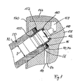
- FIG. 1 Another embodiment is shown in FIG. In the following, only differences to the preceding embodiment will be discussed, with the same reference numerals being used for corresponding elements.
- the spout 50 has adjacent to the coupling surface 56 on the mounting portion, which is partially outside the fitting housing 12.
- the inner diameter of the outflow tube 50 expands conically from the inner diameter I outside the mounting area to an inner diameter at the coupling-in surface 56.
- the threaded bushing 150 has an outer surface that matches the inner surface of the mounting region of the outflow pipe 50 and is recessed into the outflow pipe 50.
- the threaded bushing 150 is screwed into the housing inner body 156 to stop against the retaining ring 152, so that the threaded bushing 150 does not abut against the bottom portion 160 of the blind hole.
- the switching element is operatively connected to the actuating element 16 in such a way that the light source 70 is switched on when water flows out through the outflow tube 50.
- conduit 164 is filled with a filler, for example a two-coronate casting resin.
Abstract
Description
Die vorliegende Erfindung bezieht sich auf eine Armatur gemäss dem Oberbegriff des Anspruchs 1,The present invention relates to a fitting according to the preamble of claim 1,
Sanitärarmaturen dieser Art sind aus
In einer weiteren, ebenfalls in
Der vorliegenden Erfindung liegt die Aufgabe zugrunde, eine gattungsgemässe Sanitärarmatur zu schaffen, die eine wesentlich einfachere Konstruktion ermöglicht.The present invention has for its object to provide a generic sanitary fitting that allows a much simpler design.
Erfindungsgemäss wird diese Aufgabe mit einer Sanitärarmatur mit den Markmalen des Anspruchs 1 gelöst.According to the invention this object is achieved with a sanitary fitting with the Markmalen of claim 1.
Erfindungsgemäss ist das wasserführende Ausflussrohr aus einem lichtdurchlässigen - transparenten oder transluzenten - Material gefertigt und Licht wird bei einer stromaufwärts liegenden Einkopplungsfläche in das Ausflussrohr eingekoppelt. Das Ausflussrohr weist eine stromabwärts gelegene, freiliegende Stirnfläche auf, bei welcher das Licht aus dem Ausflussrohr ausgekoppelt wird.According to the invention, the water-guiding outflow pipe is made of a transparent, transparent or translucent material and light is coupled into the outflow pipe in the case of an upstream coupling-in surface. The spout has a downstream, exposed end face at which the light is extracted from the spout.
Mit der erfindungsgemässen Sanitärarmatur lassen sich zudem optische Effekte durch teilweises Freilegen der Mantelfläche des Ausflussrohrs erzielen.The sanitary fitting according to the invention also makes it possible to achieve optical effects by partially exposing the lateral surface of the outflow tube.
Gemäss einer bevorzugten Ausführungsform weist die erfindungsgemässe Sanitärarmatur einen aus einem Führungsrohr ausziehbaren Ausziehschlauch mit einem an dessen Ende angebrachten Wasserausflusskopf mit Ausflussrohr auf. Dadurch ist es möglich, den Wasserausflusskopf und somit auch die Lichtquelle in eine zum Reinigen eines Gegenstandes vorteilhafte Position zu bringen.According to a preferred embodiment, the sanitary fitting according to the invention has a pull-out tube which can be pulled out of a guide tube and has a water outflow head with an outflow tube attached to its end. This makes it possible to bring the Wasserausflusskopf and thus the light source in an advantageous for cleaning an object position.
Die erfindungsgemässe Sanitärarmatur weist im Vergleich zum Stand der Technik den weiteren Vorteil auf, dass eine Umgebung des ausfliessenden Wassers und/oder auch das ausfliessende Wasser selbst je nach Ausbildungsform der Stirnfläche beleuchtet werden kann. Durch die Beleuchtung der Umgebung des ausfliessenden Wassers kann gewährleistet werden, dass auch bei schlechter Umgebungsbeleuchtung ein zu reinigendes Objekt optimal beleuchtet wird.The sanitary fitting according to the invention has the further advantage in comparison to the prior art that an environment of the outflowing water and / or the outflowing water itself can be illuminated depending on the embodiment of the end face. By illuminating the environment of the outflowing water can be ensured that even in bad ambient lighting, an object to be cleaned is optimally illuminated.
Weitere bevorzugte Ausbildungsformen der erfindungsgemässen Sanitärarmatur sind in den weiteren abhängigen Ansprüchen angegeben.Further preferred embodiments of the inventive sanitary fitting are given in the further dependent claims.
Weitere besondere Vorteile und Wirkungsweisen ergeben sich aus der Detailbeschreibung und der Zeichnung.Further special advantages and modes of operation result from the detailed description and the drawing.
Im folgenden wird die Erfindung anhand mehrerer in der Zeichnung dargestellten Ausführungsbeispielen näher erläutert. Es zeigen rein schematisch:
- Fig. 1
- in Ansicht und teilweise im Schnitt ein erstes Ausführungsbeispiel einer erfindungsgemässe Sanitärarmatur mit einem in einem aufgeweiteten Endbereich eines Führungsrohrs angeordneten Wasserausflusskopf mit lichtführendem Ausflussrohr;
- Fig. 2
- gegenüber Fig. 1 vergrössert, im Schnitt den in den aufgeweiteten Endbereich angeordneten Wasserausflusskopf mit Ausziehschlauch;
- Fig. 3
- in Ansicht eine weitere Ausführungsform eines Wasserausflusskopfs für eine erfindungsgemässe Sanitärarmatur gemäss dem ersten Ausführungsbeispiels;
- Fig. 4
- in Ansicht in Richtung des in Fig. 1 eingezeichneten Pfeils III den aufgeweiteten Endbereich mit eingesetztem Wasserausflusskopf gemäss Fig. 1 und 2;
- Fig. 5
- in Ansicht ein zweites Ausführungsbeispiel einer erfindungsgemässe Sanitärarmatur mit einem vom Gehäuse der Sanitärarmatur abstehenden, freiliegenden Ausflussrohr;
- Fig. 6
- in einem Längsschnitt und gegenüber Fig. 5 vergrössert einen Teil des Armaturgehäuses mit dem in das Armaturgehäuse eingesetztem, lichtführenden Ausflussrohr; und
- Fig. 7
- in einem Längsschnitt einen Teil einer weitere Ausführungsform eines lichtführenden Ausflussrohrs.
- Fig. 1
- in view and partly in section, a first embodiment of a sanitary fitting according to the invention with a arranged in a widened end portion of a guide tube Wasserausflusskopf with lichtführendem discharge tube;
- Fig. 2
- compared to Figure 1 enlarged, in section the arranged in the expanded end region Wasserausflusskopf with Ausziehschlauch;
- Fig. 3
- in view of another embodiment of a Wasserausflusskopfs for a sanitary fitting according to the invention according to the first embodiment;
- Fig. 4
- in view in the direction of the drawn in Figure 1 arrow III the expanded end portion with inserted Wasserausflusskopf according to Figures 1 and 2.
- Fig. 5
- in view of a second embodiment of an inventive sanitary fitting with a protruding from the housing of the sanitary fitting, exposed spout;
- Fig. 6
- in a longitudinal section and with respect to FIG. 5 enlarges a part of the fitting housing with the light-guiding outflow pipe inserted into the fitting housing; and
- Fig. 7
- in a longitudinal section a part of another embodiment of a light-guiding outflow pipe.
Ein erstes Ausführungsbeispiel einer erfindungsgemässen Sanitärarmatur 10 ist in Fig. 1, 2 und 4 gezeigt.A first embodiment of a
Wie Fig. 1 zeigt, weist die Sanitärarmatur 10 ein Armaturgehäuse 12 auf, von welchem nach unten ein Montagestutzen 14 absteht. Dieser ist dazu bestimmt, die Sanitärarmatur 10 an einer nicht gezeigten Montagefläche eines Waschtisches mittels einer Mutter 14' zu befestigen. Das Armaturgehäuse 12 weist eine Ausnehmung mit einer in bekannter Art und Weise darin eingesetzten Mischpatrone 15 mit Betätigungselement 16 zur Steuerung des Wasserflusses auf. Vom Armaturgehäuse 12 steht in vertikaler Richtung ein um eine vertikale Achse schwenkbares Führungsrohr 18 ab. vom Armaturgehäuse 12 her verjüngt sich das Führungsrohr 18 glockenartig auf einen Durchmesser D und verläuft anfänglich geradlinig und dann nahezu in einem Halbkreisbogen. Ein freier Endbereich 20 des Führungsrohrs 18 weitet sich glockenartig und stetig auf. Das Innere des freien Endbereichs 20 bildet eine Aufnahme 22 für einen herausziehbaren und wiedereinsetzbaren Wasserausflusskopf 24.As shown in FIG. 1, the
Der Wasserausflusskopf 24 ist fest mit einem durch das Innere des Führungsrohrs 18, des Armaturgehäuses 12 und des Montagestutzen 14 hindurch verlaufenden Ausziehschlauch 26 verbunden. Der Ausziehschlauch 26 verläuft wie allgemein bekannt in einer Schlaufe zurück zum Armaturgehäuse 12. Der Ausziehschlauch 26 weist (siehe Fig. 2) einen aussenliegenden Mantelschlauch 86 und einen im Inneren des Mantelschlauchs 86 angeordneten Wasserschlauch 28 auf. Zwischen dem Mantelschlauch 86 und dem Wasserschlauch 28 ist eine elektrische Leitung 84, vorzugsweise eine mehradrige Litze, angeordnet. Der Wasserschlauch 28 ist dazu bestimmt, Mischwasser von der Mischpatrone 15 zum Wasserausflusskopf 24 zu führen. Die Mischpatrone 15 ist zudem in bekannter Art und Weise mit nicht gezeigten Kalt- und Warmwasserspeiseleitung verbunden.The Wasserausflusskopf 24 is firmly connected to a through the interior of the
Wie in den Fig. 1, 2 und 4 gezeigt, weist ein Gehäuse 36 des Wasserausflusskopfs 24 eine glockenartige Form auf, die der Form der Aufnahme 22 angepasst ist. Um eine einfache Handhabung zu ermöglichen, weist das Gehäuse 36 eine zapfenartige Auszugshilfe 38 auf, die in radialer Richtung absteht. Der freie Endbereich 20 des Führungsrohrs 18 weist hierzu (siehe Fig. 4) einen am Ende der Führungsrohrs 18 offenen Führungsschlitz 40 auf, durch welchen die Auszugshilfe 38 beim Einfahren und beim Ausfahren des Wasserausflusskopfs 24 geführt wird. Das Gehäuse 36 weist weiter einen Wulst 42 auf, der, falls der Wasserausflusskopf 24 in die Aufnahme 22 eingesetzt ist, in den Führungsschlitz 40 eingreift. Ausser im Bereich des Wulstes 42 und eines stromaufwärts gelegenen Endbereichs 44 ist das Gehäuse 36 dünnwandig, mit im Wesentlichen gleichbleibender Wandstärke ausgebildet. An dem stromabwärts gelegenen Ende - ausser im Bereich der Wulst 42 - weist das Gehäuse 36 eine umlaufende Gehäusestirnfläche 46 auf, wobei die Wulst 42 die Gehäusestirnfläche 46 in Strömungsrichtung überragt.As shown in FIGS. 1, 2 and 4, a
Der Wasserausflusskopf 24 weist ein wasserführendes, rotationssymmetrisches, lichtdurchlässiges, lichtleitendes und mit dem Wasserschlauch 28 verbundenes Ausflussrohr 50 auf. Das Ausflussrohr 50 ist beispielsweise aus Acrylglas oder einem anderen transparenten oder translueszenten Material gefertigt. Das Ausflussrohr 50 weist in einem stromabwärts gelegenen Abschnitt einen hohlzylinderförmigen Lichtübertragungsbereich 52 auf. Dieser Lichtübertragungsbereich 52 ist einerseits, stromaufwärtsgelegen von einer Einkopplungsfläche 56 und andererseits, am stromabwärts liegenden Ende des Lichtübertragungsbereichs 52 und zugleich des Ausflussrohrs 50 von einer freiliegende Stirnfläche 58 begrenzt. Die Stirnfläche 58 liegt in Ausflussrichtung der Einkopplungsfläche 56 gegenüber und die Stirnfläche 58 wie auch die Einkopplungsfläche 56 liegen rechtwinklig zur Rotationsachse des Ausflussrohrs 50.The
Das Ausflussrohr 50 weist beabstandet von der Stirnfläche 58 eine radial aussenliegende, stromaufwärts ausgerichtete Schulter 60 auf, die bei in das Gehäuse 36 eingesetztem Ausflussrohr 50 an die Gehäusestirnfläche 46 anliegt. Zwischen der Schulter 60 und der Stirnfläche 58 weist das Ausflussrohr 50 eine freiliegende Mantelfläche 72 auf, wobei die freiliegende Mantelfläche 72 kontinuierlich in eine aussenliegende Oberfläche des Gehäuses 36 kontinuierlich übergeht. Die freiliegende Mantelfläche 72 ist auch bei in die Aufnahme 22 eingesetztem Wasserausflusskopf 24 freiliegend.The
Angrenzend an den Lichtübertragungsbereich 52 weist das Ausflussrohr 50 einen stutzenaztigen Verbindungsbereich 64 auf, wobei sich das Ausflussrohr 50 im Übergangsbereich vom Lichtübertragungsbereich 52 zum Verbindungsbereich 64 stufenartig verjüngt.Adjacent to the
Ein Innendruchmesser des Ausflussrohrs verjüngt sich in zwei Stufen vom grösseren Innendurchmesser des Lichtübertragungsbereichs 52 auf den kleineren Innendurchmesser des Verbindungsbereich 64, wobei der Innendurchmesser derart gewählt ist, dass ein weiter unten beschriebenen Strahlregler 110 in das Ausflussrohr 50 eingesetzt werden kann.An inner diameter of the outflow tube tapers in two stages from the larger inner diameter of the
Eine Lichtquelle 70 ist direkt anliegend an die Einkopplungsfläche 56 des Ausflussrohrs 50 angeordnet. Das bei der Einkopplungsfläche 56 eingekoppelte Licht der Lichtquelle 70 wird durch den Lichtübertragungsbereich 52 zur Stirnfläche 58 übertragen und bei dieser zumindest teilweise aus dem Ausflussrohr 50 ausgekoppelt. Das Licht wird zudem im Bereich der freiliegenden Mantelfläche 72 zwischen der Schulter 60 und der Stirnfläche 58 - ausser im Bereich der Wulst 42 - aus dem Ausflussrohr 50 ausgekoppelt.A light source 70 is arranged directly adjacent to the
Als Lichtquelle 70 werden mehrere, vorzugsweise neun Licht emittierende Dioden (LED) 74 verwendet, wobei die Dioden 74 in Umfangsrichtung in regelmässigen Abständen angeordnet sind und eine Lichtkegelachse jeder Diode 74 zumindest nahezu rechtwinklig durch die Einkopplungsfläche 56 hindurch und parallel zur Rotationsachse des Ausflussrohrs 50 verläuft. Durch die Ausrichtung der Lichtkegelachsen wird erreicht, dass ein möglichst grosser Anteil des von den Dioden 74 ausgestrahlten Lichts durch die Stirnfläche 58 und durch die Mantelfläche 72 austritt. Neben weissem Licht kann die Lichtquelle 70 auch farbiges Licht ausstrahlen.As a light source 70, a plurality of, preferably nine light-emitting diodes (LED) 74 are used, wherein the diodes 74 are arranged in the circumferential direction at regular intervals and a light cone axis of each diode 74 at least approximately at right angles through the
Die Dioden 74 sind auf einer kreisringförmigen Leiterplatine 76 angeordnet, welche das Ausflussrohr 50 im Verbindungsbereich 64 umgreift. Auf einer weiteren, elektrisch mit der kreisringförmigen Leiterplatine 76 verbundenen Leiterplatine 78 ist eine Steuerschaltung für die Lichtquelle 70 mit einem Schaltelement 80 angeordnet. Die weitere Leiterplatine 78 ist an den Verbindungsbereich 64 des Ausflussrohrs 50 und in Strömungsrichtung oberhalb der kreisringförmigen Leiterplatine 76 befestigt. Das Schaltelement 80 ist ein Taster 80' mit Tastkopf 82, wobei der Tastkopf 82 den Wulst 42 des Gehäuses 36 in Strömungsrichtung unterhalb der Auszugshilfe 38 dicht durchstösst. Mittels des Tasters 80' kann die Lichtquelle 70 je nach Ausgestaltung der Schaltelektronik auf der weiteren Leiterplatine 78 angesteuert werden. Denkbar ist, dass der Taster 80' die Lichtquelle 70 bei einer ersten Betätigung einschaltet und bei einer weiteren Betätigung wieder ausschaltet, wobei das Ausschalten zeitverzögert erflogen kann. Eine weitere Möglichkeit besteht darin, dass die Lichtquelle 70 durch eine Zeitschaltung nach einer gewissen Zeitdauer ausgeschaltet wird.The diodes 74 are arranged on an annular printed
Die Versorgung der elektrischen Schaltung und der Lichtquelle 70 mit elektrischer Energie wird über die elektrische Leitung 84 sichergestellt, welche mit einer Stromversorgung elektrisch verbunden ist. Die Stromversorgung wird vorzugsweise in einer eigenen Box unterhalb des Waschtisches angebracht und ist dazu ausgebildet, im Nassbereich angewandt zu werden. Als Energiequelle für die Stromversorgung gelangt ein Netzgerät zur Anwendung, wobei anstelle des Netzgeräts auch Batterien oder Akkumulatoren verwendet werden können.The supply of electric power to the electrical circuit and the light source 70 is ensured via the
Um eine dichte und zugleich feste Verbindung des Ausziehschlauchs 26 mit Wasserschlauch 28 und dem Wasserausflusskopf 24 mit Ausflussrohr 50 herzustellen, überragt der innenliegende Wasserschlauch 28 den aussenliegenden Mantelschlauch 86. Ein Endbereich des Ausziehschlauchs 26 ist vollständig von einer Hülse 90 umfasst. In den Wasserschlauch 28 ist vom freien Ende her ein Klemmzapfen 92 eingeführt, sodass der Wasserschlauch 18 zwischen dem Klemmzapfen 92 und der Hülse 90 fest und dichtend eingeklemmt ist. Der Klemmzapfen 92 weist einen Strömungskanal auf, dessen Durchmesser im Wesentlichen gleich dem Durchmesser des nicht gedehnten Wasserschlauchs 28 entspricht. Eine Länge des Klemmzapfens 92 ist derart gewählt, dass der Klemmzapfen 92 nur in den Bereich des Wasserschlauchs 28 eingeführt werden kann, der den Mantelschlauch 86 überragt, sodass der Klemmzapfen 92 in Strömungsrichtung vom Mantelschlauch 86 beabstandet ist. Dadurch ist es möglich, die zwischen dem Mantelschlauch 86 und dem Wasserschlauch 28 angeordnete elektrische Leitung 84 durch eine Durchgangsöffnung 94 der Hülse 90 zur weiteren Leiterplatin 78 zu führen, ohne die elektrische Leitung 84 zwischen dem Mantelschlauch 86 und dem Klemmzapfen 92 einzuklemmen.In order to produce a tight and at the same time firm connection of the
Die Hülse 90 weist ein Aussengewinde auf und ist in den Verbindungsbereich 64 des Ausflussrohrs 50 eingewindet. Um eine dichte Verbindung zwischen dem Klemmzapfen 92 und dem Ausflussrohr 50 herzustellen, weist der Klemmzapfen 92 eine rechtwinklig zur Ausflussrichtung liegende Kreisringfläche und der Verbindungsbereich 64 eine dieser Kreisringfläche gegenüberliegende, ebenfalls kreisringförmige Kontaktfläche auf. Zwischen der Kreisringfläche und der Kontaktfläche ist ein Dichtungsring 96 eingeklemmt. Angrenzend an die Kontaktfläche ist der Verbindungsbereich wasserführend und weist einen Innendurchmesser auf, der im Wesentlichen gleich dem Innendurchmesser des Klemmzapfens 92 ist.The
Das Gehäuse 36 ist in einem Bereich, in welchem der Ausziehschlauch 26 in den wasserausflusskopf 24 eintritt und in einem Bereich, in welchem das Gehäuse 36 an den Lichtübertragungsbereich 52 des Ausflussrohrs 50 anliegt dicht mit dem Ausziehschlauch 26 beziehungsweise mit dem Ausflussrohr 50 verklebt, wodurch eine Verbindung des Gehäuses 36 mit dem Ausflussrohr 50 beziehungsweise mit dem Mantelschlauch 86 hergestellt wird und weder Schmutz noch Feuchtigkeit ins Innere des Wasserausflusskopfs 24 eindringen können.The
In das Ausflussrohr 50 ist vom stromabwärts liegenden Ende her ein Aussengewinde 98 aufweisender Strahlregler 110 eingeschraubt. Der Strahlreger 110 ist zylinderförmig ausgebildet, weist eine in das Ausflussrohr passende Form auf und ist in Strömungsrichtung vollständig in das Ausflussrohr 50 versenkt. Ein stromabwärtsliegender, kronenartiger Steckbereich 112 ist durch in Umfangsrichtung regelmässig angeordnete und in Strömungsrichtung ausgerichtete Vertiefungen 114 und Erhöhungen 114' ausgebildet. In Strömungsrichtung ist am Strahlregler 110 zwischen dem Aussengewinde 98 und dem Steckbereich 112 ein O-Ring 116 zum Abdichten des Strahlreglers 110 gegenüber dem Ausflussrohr 50 angeordnet. Als Strahlregler 110 kann ein Perlator der Firma Neoperl zur Anwendung gelangen.Into the
Der kronenartige Steckbereich 112 ermöglicht ein einfaches Auswechseln des Strahlreglers 110 durch einen neuen Strahlreger desselben Typs. Zum Auswechseln des Strahlreglers 110 wird der neuer Strahlregler auf den Steckbereich 112 des in das Ausflussrohr 50 eingebauten Strahlreglers 110 aufgesteckt. Mittels des neuen Strahlreglers kann der ins Ausflussrohr 50 eingeschraubte Strahlregler 110 herausgeschraubt werden. Der neue Strahlregler wird in analoger Weise eingeschraubt. Durch den kronenartige Steckbereich 112 kann auf Spezialwerkzeug zum Auswechseln des Strahlreglers 110 verzichtet werden.The crown-
In einer weiteren Ausführungsform des ersten Ausführungsbeispiels ist das Gehäuse 36 anstelle aus Metall aus einem Kunststoff gefertigt. Der Tastkopf 82 des Tasters 80' kann, wie in Fig. 2 gezeigt, dicht durch das Gehäuse 36 hindurch geführt sein oder mit einer Membran überspannt sein. Die Membran kann beispielsweise mittels eines allgemein bekannten Zweikomponentenspritzverfahrens an das aus Kunststoff gefertigte Gehäuse angespritzt werden.In a further embodiment of the first embodiment, the
Eine weitere Ausführungsform eines Wasserausflusskopfs ist in Fig. 3 gezeigt, wobei im Folgenden nur auf Unterschiede zum oben beschriebenen Wasserausflusskopf eingegangen wird. Für entsprechende Elemente werden dieselben Bezugszeichen verwendet.Another embodiment of a Wasserausflusskopfs is shown in Fig. 3, which will be discussed below only to differences from the above-described Wasserausflusskopf. The same reference numerals are used for corresponding elements.
Das Schaltelement 80 ist in die Auszugshilfe 38 integriert. Hierfür weist die Auszugshilfe 38 eine in axialer Richtung der Auszugshilfe verlaufende, nach aussen offene Ausnehmung auf, in welche das Schaltelement 80 eingesetzt ist. Von einem Boden der Ausnehmung führt ein Leitungskanal 120 ins Innere des Wasserausflusskopfes 24. Das Schaltelement 80 in Form eines Tasters 80' weist einen aus der Ausnehmung herausstehenden Tastkopf 82 auf, welcher in dessen Umfangrichtung vollständig von einer Schutzkappe 122 umfasst ist. Die Schutzkappe 122 ist auf die Auszugshilfe 38 aufgeschraubt und ist vorzugsweise gummielastisch. Zwischen der Schutzkappe 122 und dem Schaltelement 80 ist ein an die innere Mantelfläche der Ausnehmung anliegender Dichtungsring 124 angeordnet.The switching
Die durch den Ausziehschlauch 24 geführte elektrische Leitung 84 ist mit der die Lichtquelle 70 tragenden Leiterplatine 76 elektrisch verbunden. Die Leiterplatine 76, die in allgemein bekannter Art und Weise festgeklemmt ist, trägt zudem die Schaltelektronik. Das Schaltelement 80 ist über eine durch den Leitungskanal 120 geführte elektrische Schaltleitung 126 mit der Leiterplatine 76 verbunden.The guided through the
Das Gehäuse 36 des Wasserausflusskopf 24 ist ausser im Bereich der Wulst 42 dünnwandig ausgebildet. Der in den Führungsschlitz 40 eingreifende Wulst endet in Längsrichtung des Gehäuses 36 auf derselben Höhe wie das Gehäuse 36, sodass der Wulst 42 nicht über die Gehäusestirnfläche 46 vorsteht und das Ausflussrohr 50 eine umlaufende, freiliegende Mantelfläche 72 aufweist.The
Im stromaufwärts gelegenen Endbereich 44 weist das Gehäuse 36 mehrere, in umfangsrichtung gleichmässig angeordnete radiale Durchgänge 128 auf. Ein in radialer Richtung zwischen dem Ausflussrohr 50 bzw. der Hülse 90 und dem Gehäuse 36 und in Längsrichtung zwischen den Durchgängen 128 und der Einkopplungsfläche 56 gelegener Hohlraum ist mit einer Füllmasse, beispielsweise ein Zweikomponenten-Giessharz, aufgefüllt, welcher durch die Durchgänge in den Hohlraum eingefüllt wird.In the
In einer weiteren Ausführungsform ist das Betätigungselements 16 der Mischpatrone 15 mit einem im Armaturgehäuse 12 angeordneten Schaltelement wirkverbunden, sodass die Lichtquelle bei ausströmendem Wasser eingeschaltet ist.In a further embodiment, the
In einer weiteren Ausführungsform des ersten Ausführungsbeispiels wird anstelle der Mischpatrone mit Betätigungselement zum manuellen Regeln des Wasserdurchflusses durch die Sanitärarmatur 10 ein elektronisch gesteuertes Ventil verwendet. Das Ventil ist über eine Steuerleitung der mehradrigen elektrischen Leitung 84 mit der elektrischen Schaltung im Wasserausflusskopf 24 verbunden. Durch die Betätigung des Schaltelements 80 wird zum einen die Lichtquelle 70 im Wasserausflusskopf 24 und zum andern das elektrisch gesteuerte Ventil angesteuert.In a further embodiment of the first embodiment, an electronically controlled valve is used instead of the mixing cartridge with actuator for manually controlling the flow of water through the
In einer weiteren Ausführungsform des ersten Ausführungsbeispiels liegt die Stirnfläche 58, nicht rechtwinklig zur Ausflussrichtung. Die Stirnfläche kann abgewinkelt zur Ausflussrichtung liegen, kann eine gewölbte Fläche sein oder nahezu eine beliebige Form aufweisen, wodurch ein Lichtausfall aus dem Ausflussrohr 50 nahezu beliebig beeinflusst werden kann. Die freiliegende Mantelfläche kann ebenfalls in ihren optischen Eigenschaft verändert werden, beispielsweise durch Aufrauen der Oberfläche, wodurch das austretende Licht stärker gestreut wird, oder durch einfärben der Mantelfläche.In a further embodiment of the first Embodiment is the
In einer weiteren Ausführungsform des ersten Ausführungsbeispiels weist die Leiterplatine 76 einen grösseren Aussendurchmesser auf, sodass die Leiterplatine 76 an das Gehäuse 36 anliegt.In a further embodiment of the first embodiment, the printed
Ein zweites Ausführungsbeispiel wird mit Bezug auf die Fig. 5 und 6 beschrieben.A second embodiment will be described with reference to FIGS. 5 and 6.
Wie Fig. 5 zeigt, ist ein hohlzylinderförmiges Armaturgehäuse 12 mit einem kreisförmigen Querschnitt einer erfindungsgemässen Sanitärarmatur 10 vertikal ausgerichtet. Die Sanitärarmatur 10 ist dazu bestimmt, auf einer Montagefläche eines Waschtischs mittels einer nach unten wegstehender Befestigungsspindel 154 in bekannter Art und Weise befestigt zu werden. Im Inneren des Armaturgehäuses 12 ist ein (siehe Fig. 6) Gehäuseinnenkörper 156 angeordnet, welcher in radialer Richtung an das Armaturgehäuse 12 anliegt. Nach unten stehen zwei Anschlussleitungen 142, 142' vom Gehäuseinnenkörper 156 ab, welche dazu bestimmt sind, warmes und kaltes Wasser der Sanitärarmatur 10 zuzuführen. In das Armaturgehäuse 12 ist von oben her eine Mischpatrone 144 mit einem oberhalb des Armaturgehäuses 12 angeordneten Betätigungselement 16 in bekannter Art und Weise eingesetzt.As FIG. 5 shows, a hollow-cylindrical
In das Armaturgehäuse 12 ist ein kreiszylinderförmiges Ausflussrohr 50 eingesetzt, sodass die Zylinderachse des Armaturgehäuses 12 mit der Zylinderachse des Ausflussrohrs 50 einen Winkel von 55 Grad einschliesst und das Ausflussrohr 50 nach unten geneigt vom Armaturgehäuse absteht. Der Aussendurchmesser des Ausflussrohrs 50 ist kleiner als der Aussendurchmesser des Armaturgehäuses 12.In the
Das Ausflussrohr 50 ist aus einem lichtdurchlässigen Material gefertigt, wobei das Material transparente und/oder translueszente Eigenschaften aufweist. Beispielsweise kann das Ausflussrohr 50 aus Glas oder Acrylglas gefertigt sein. Die Oberfläche des Rohrs ist glatt ausgebildet, kann jedoch auch rau bzw. aufgeraut sein, wodurch optische Eigenschaften des Ausflussrohrs 50 beeinflusst werden könne.The
Wie in Fig. 5 und 6 gezeigt, weist das Ausflussrohr 50 an einem stromabwärts gelegenen Ende eine Stirnfläche 58 und an einem stromaufwärts gelegenen Ende, gegenüber der Stirnfläche 58 gelegen, eine Einkopplungsfläche 56 auf. Ein Innendurchmesser I des Ausflussrohrs 50 ist konstant ausser in einem Montagebereich, der an die Einkopplungsfläche 56 angrenzt und innerhalb des Armaturgehäuses 12 liegt. Der Montagebereich weist einen grösseren Innendurchmesser auf, als der Innendurchmesser I. Im Montagebereich ist eine ein Innengewinde aufweisende Gewindehülse 146 ins Ausflussrohr 50 eingesetzt, vorzugsweise eingeklebt. In Strömungsrichtung unterhalb des Montagebereichs ist das Ausflussrohr 50 wasserführend. In die Gewindehülse 146 ist eine Gewindebuchse 150 eingeschraubt, die aus dem Ausflussrohr 50 bei der Einkopplungsfläche 56 herausragt. Die Gewindebuchse 150 ist von einem U-profilförmiger Haltering 152 umgriffen, dessen Öffnung in Richtung der Einkopplungsfläche 56 ausgerichtet ist und in dem eine ringförmige Leiterplatine 76 angeordnet ist. Die ringförmige Leiterplatine 76 trägt eine Lichtquelle 70, die aus mehreren Licht emittierenden Dioden (LED) 74 besteht, vorzugsweise als oberflächenmontierbare Bauelemente (SMD) gefertigt. Die Dioden 74 liegen an die Einkopplungsfläche 56 des Ausflussrohres 50 derart an, dass die Lichtkegelachse jeder Diode 74 rechtwinklig durch die Einkopplungsfläche 56 und die Stirnfläche 58 hindurch und parallel zur Zylinderachse des Ausflussrohrs 50 verlaufen. Die Dioden 74 sind in Umfangsrichtung in regelässigen Abständen auf der Leiterplatine 76 angebracht. Selbstverständlich können anstelle der Dioden 74 auch andersartig ausgebildete Lichtquellen 70 verwendet werden.As shown in FIGS. 5 and 6, the
Das von den Dioden 74 in das Ausflussrohr 50 eingeleitete Licht wird von diesem zur Stirnfläche 58 und zu einer radial aussenliegenden, ausserhalb des Armaturgehäuses 12 liegende Mantelfläche 72 des Ausflussrohrs 50 geführt und bei der Stirnfläche 58 wie auch bei der freiliegenden Mantelfläche 72 aus diesem ausgekoppelt.The introduced from the diodes 74 in the
In Strömungsrichtung oberhalb des Halterings 152 weist die Gewindehülse ein Aussengewinde auf.In the flow direction above the retaining
Das Armaturgehäuse 12 weist eine Ausnehmung auf, durch welche das Ausflussrohr 50 hindurch geführt ist. Der Gehäuseinnenkörper 156 weist ein kreiszylinderförmiges, gestuftes Sackloch zum Aufnehmen des Ausflussrohrs 50 auf, wobei das Sackloch angrenzend an das Armaturgehäuse 12 einen grösseren dem Aussendurchmesser des Ausflussrohrs 50 entsprechenden Innendurchmesser und beabstandet vom Armaturgehäuse 12 einen kleineren Innendurchmesser aufweist. Der Bereich des Sacklochs mit dem grösseren Innendurchmesser ist derart ausgebildet, dass das Ausflussrohr 50 und der Haltering 152 in diesen Bereich eingsetzbar sind. Das Sackloch weist im Bereich des kleineren Durchmessers ein Innengewinde auf, in welches die Gewindebuchse 150 eingeschraubt ist.The
In einen Bodenbereich 160 des Sacklochs mündet ein von der Mischpatrone 144 her kommender Mischwasserkanal 158, der Mischwasser von der Mischpatrone 144 zum Ausflussrohr 50 führt.A
Die Gewindebuchse 150 ist in Anschlag an den Bodenbereich 160 in den Gehäuseinnenkörper 156 eingeschraubt. Die Gewindebuchse 150 weist radial innenliegend eine dem Bodenbereich 160 zugewandete Anschlagsfläche auf, an welche ein Strahlregler 110 anliegt. Zwischen dem Strahlregler 110 und dem Bodenbereich 160 ist ein Dichtungsring 162 eingeklemmt. Dieser bildet einen Übergang vom Mischwasserkanal 158 zur Gewindebuchse 150 mit in dieser eingesetztem Strahlregler 110 dicht aus, sodass ausströmendes Wasser nicht auf eine radial aussenliegende Seite der Gewindebuchse 150 und des Ausflussrohrs 50 gelangen können.The threaded
Um eine mehradrige elektrische Leitung 84 durch den Gehäuseinnenkörper 156 zur Leiterplatine 76 mit der auf dieser angeordneten Lichtquelle 70 zu führen, weist der Gehäuseinnenkörper 156 einen Leitungskanal 164 auf, der in das Sackloch, in einen Bereich, in welchem der Haltering 152 angeordnet ist, mündet. Angrenzend an den Leitungskanal 164 weist der Haltering 152 eine in radialer Richtung ausgerichtete Durchgangsöffnung 166 auf, sodass die elektrische Leitung 84 durch den Leitungskanal 164 und durch die Durchgangsöffnung 166 hindurch geführt werden kann. Die elektrische Leitung 84 ist einerseits mit der im Haltering 152 angeordneten Leiterplatine 76 und andererseits mit einer Schaltelektronik elektrisch verbunden, die durch ein Schaltelement 80 gesteuert wird.In order to guide a multicore
Das Schaltelement 80 ist, wie in Fig. 5 gezeigt, ein allgemein bekanntes Schaltelement für eine Raumbeleuchtung. Mittels des Schaltelements 80 wird eine stromzufuhr zur Schaltelektronik eingeschaltet beziehungsweise ausgeschaltet. Die Schaltelektronik ist infolge der sehr schlanken Bauweise vorzugsweise in einer Box 170 unterhalb des Waschtisches angebracht. In der Box 170 kann beispielsweise ein Transformator angeordnet sein, dessen Stromzufuhr mittels des Schaltelements 80 eingeschaltet bzw. ausgeschaltet werden kann und die Schaltelektronik mit Strom versorgt.The switching
Für das Einschalten und Ausschalten der Lichtquelle 70 sind unterschiedlichste Möglichkeiten vorstellbar. Beispielsweise kann das Einschalten wie auch das Ausschalten über eine Dimmerschaltung geschehen, sodass die Lichtstärke kontinuierlich zu beziehungsweise abnimmt.For switching on and off the light source 70 a variety of ways are conceivable. For example, the switching on and off via a dimmer circuit can be done so that the light intensity continuously increases or decreases.
Weiter kann die Lichtstärke mittels eines Sensors an die aktuellen Lichtverhältnisse im Raum angepasst werden.Furthermore, the light intensity can be adjusted by means of a sensor to the current light conditions in the room.
In einer weiteren Ausführungsform kann das Schaltelement als ein Strömungswächter ausgebildet sein, der ein Wasserdurchfluss durch mindestens eine der Anschlussleitungen 142, 142' detektiert. Bei Wasserdurchfluss durch die Anschlussleitungen 142, 142' und somit durch die Sanitärarmatur 10, steuert der Strömungswächter die Schaltelektronik derart an, dass die Lichtquelle bei Wasserausfluss aus der Sanitärarmatur 10 mit Strom versorgt wird.In a further embodiment, the switching element may be formed as a flow monitor, which is a water flow through at least one of
Das Ausschalten der Lichtquelle kann zudem zeitverzögert zum Schliessen eines Ventils der Mischpatrone 144 sein.Turning off the light source may also be time delayed to close a valve of the mixing
In einer weiteren Ausführungsform kann das Schaltelement als Infrarotdetektor ausgebildet sein, mittels dessen ein elektromagnetisches Ventil der Sanitärarmatur in bekannter Art und Weise angesteuert wird. Das als Infrarotdetektor ausgebildete Schaltelement wird zudem zur Steuerung der Schaltelektronik verwendet, sodass bei ausfliessendem Wasser die Lichtquelle 70 mit Strom versorgt wird.In a further embodiment, the switching element may be formed as an infrared detector, by means of which an electromagnetic valve of the sanitary fitting is driven in a known manner. The trained as an infrared detector switching element is also used to control the switching electronics, so that when running water, the light source 70 is supplied with power.
Ein weiteres Ausführungsbeispiel ist in Fig. 7 gezeigt. Im folgenden wird nur auf Unterschiede zum vorangehenden Ausführungsbeispiel eingegangen, wobei für entsprechende Elemente dieselben Bezugszeichen verwendet werden.Another embodiment is shown in FIG. In the following, only differences to the preceding embodiment will be discussed, with the same reference numerals being used for corresponding elements.
Das Ausflussrohr 50 weist angrenzend an die Einkopplungsfläche 56 den Montagebereich auf, welcher teilweise ausserhalb des Armaturgehäuses 12 liegt. Der Innendurchmesser des Ausflussrohrs 50 weitet sich konisch vom Innendurchmesser I ausserhalb des Montagebereichs auf einen Innendurchmesser bei der Einkopplungsfläche 56 auf. Die Gewindebuchse 150 weist an ihrem in das Ausflussrohr 50 eingesetzten Endbereich eine zu einer inneren Mantelfläche des Montagebereichs des Ausflussrohrs 50 passende Aussenfläche auf und ist in das Ausflussrohr 50 eingelebt.The
Die Gewindebuchse 150 ist in den Gehäuseinnenkörper 156 auf Anschlag an den Haltering 152 eingeschraubt, sodass die Gewindebuchse 150 nicht an den Bodenbereich 160 des Sacklochs anliegt.The threaded
In einer weiteren Ausführungsform ist das Schaltelement mit dem Betätigungselement 16 derart wirkverbunden, dass beim Ausfliessen von Wasser durch das Ausflussrohr 50 die Lichtquelle 70 eingeschaltet ist.In a further embodiment, the switching element is operatively connected to the
In einer weiteren Ausführungsform wird der Leitungskanal 164 mit einem Füllmittel, beispielsweise ein Zweikoraponentengiessharz, aufgefüllt.In a further embodiment, the
Claims (14)
Priority Applications (10)
| Application Number | Priority Date | Filing Date | Title |
|---|---|---|---|
| ES05005389T ES2314505T3 (en) | 2005-03-11 | 2005-03-11 | SANITARY TAP WITH A DUCT TUBE DRIVER OF THE LIGHT. |
| PT05005389T PT1705297E (en) | 2005-03-11 | 2005-03-11 | Sanitary fixture with light-guiding discharge tube |
| EP05005389A EP1705297B1 (en) | 2005-03-11 | 2005-03-11 | Sanitary fixture with light-guiding discharge tube |
| DE502005005614T DE502005005614D1 (en) | 2005-03-11 | 2005-03-11 | Sanitary fitting with a light-conducting spout |
| AT05005389T ATE410557T1 (en) | 2005-03-11 | 2005-03-11 | SANITARY FITTING WITH A LIGHT CONDUCTING OUTLET PIPE |
| CA002535197A CA2535197A1 (en) | 2005-03-11 | 2006-02-03 | Sanitary fitting with a lightguide outflow pipe |
| TW095103993A TWI372809B (en) | 2005-03-11 | 2006-02-07 | Sanitary fitting with a lightguide outflow pipe |
| US11/372,207 US7467874B2 (en) | 2005-03-11 | 2006-03-10 | Sanitary fitting with a lightguide outflow pipe |
| CN2006100547733A CN1831254B (en) | 2005-03-11 | 2006-03-10 | Sanitary fixture with light-guiding discharge tube |
| US12/216,603 US7794095B2 (en) | 2005-03-11 | 2008-07-08 | Sanitary fitting with a lightguide outflow pipe |
Applications Claiming Priority (1)
| Application Number | Priority Date | Filing Date | Title |
|---|---|---|---|
| EP05005389A EP1705297B1 (en) | 2005-03-11 | 2005-03-11 | Sanitary fixture with light-guiding discharge tube |
Publications (2)
| Publication Number | Publication Date |
|---|---|
| EP1705297A1 true EP1705297A1 (en) | 2006-09-27 |
| EP1705297B1 EP1705297B1 (en) | 2008-10-08 |
Family
ID=34934217
Family Applications (1)
| Application Number | Title | Priority Date | Filing Date |
|---|---|---|---|
| EP05005389A Active EP1705297B1 (en) | 2005-03-11 | 2005-03-11 | Sanitary fixture with light-guiding discharge tube |
Country Status (9)
| Country | Link |
|---|---|
| US (1) | US7467874B2 (en) |
| EP (1) | EP1705297B1 (en) |
| CN (1) | CN1831254B (en) |
| AT (1) | ATE410557T1 (en) |
| CA (1) | CA2535197A1 (en) |
| DE (1) | DE502005005614D1 (en) |
| ES (1) | ES2314505T3 (en) |
| PT (1) | PT1705297E (en) |
| TW (1) | TWI372809B (en) |
Cited By (2)
| Publication number | Priority date | Publication date | Assignee | Title |
|---|---|---|---|---|
| WO2009024219A1 (en) | 2007-08-21 | 2009-02-26 | Hansgrohe Ag | Sanitary fitting with an outlet made of glass |
| EP2148015A1 (en) | 2008-07-21 | 2010-01-27 | Kwc Ag | Sanitary fitting with light conducting discharge tube |
Families Citing this family (17)
| Publication number | Priority date | Publication date | Assignee | Title |
|---|---|---|---|---|
| DE102006021697B3 (en) * | 2006-05-10 | 2007-10-11 | Hansa Metallwerke Ag | Shower has removable head containing light-emitting diode and rechargeable battery which supplies it with current, connecting section at rear of head plugging into charger for battery or into handle when shower is to be used |
| USD612015S1 (en) | 2009-04-16 | 2010-03-16 | Kwc Ag | Faucet |
| IT1403102B1 (en) * | 2010-12-15 | 2013-10-04 | Amfag S P A Ora Amfag S R L | SHOWER PERFECTED FOR KITCHEN SINK. |
| US9074357B2 (en) | 2011-04-25 | 2015-07-07 | Delta Faucet Company | Mounting bracket for electronic kitchen faucet |
| US9057184B2 (en) | 2011-10-19 | 2015-06-16 | Delta Faucet Company | Insulator base for electronic faucet |
| US9068327B2 (en) * | 2012-05-19 | 2015-06-30 | Oskar L. Granstrand | Flow meter for the measuring of fluid volumes originating from a faucet |
| US10125901B2 (en) | 2013-03-15 | 2018-11-13 | Delta Faucet Company | Sprayer hose assembly |
| US9333698B2 (en) | 2013-03-15 | 2016-05-10 | Delta Faucet Company | Faucet base ring |
| CN103994276A (en) * | 2014-04-04 | 2014-08-20 | 路达(厦门)工业有限公司 | Faucet structure with light |
| CN105318099B (en) * | 2014-06-06 | 2018-03-23 | 成霖企业股份有限公司 | Pull-out faucet can be illuminated |
| CN105299312B (en) * | 2014-06-06 | 2018-02-27 | 成霖企业股份有限公司 | Pull-out faucet can be illuminated |
| US10662625B2 (en) | 2014-12-12 | 2020-05-26 | Delta Faucet Company | Sprayer hose assembly |
| US10113739B2 (en) | 2017-01-06 | 2018-10-30 | Delta Faucet Company | Connector for an electronic faucet |
| US10697628B2 (en) | 2017-04-25 | 2020-06-30 | Delta Faucet Company | Faucet illumination device |
| CN108426074A (en) * | 2018-02-05 | 2018-08-21 | 芜湖雅园装饰工程有限公司 | A kind of intelligent tap |
| US11602032B2 (en) | 2019-12-20 | 2023-03-07 | Kohler Co. | Systems and methods for lighted showering |
| US11603987B2 (en) | 2020-08-31 | 2023-03-14 | Kraus Usa Plumbing Llc | Lighting system for fixtures and appliances |
Citations (8)
| Publication number | Priority date | Publication date | Assignee | Title |
|---|---|---|---|---|
| DE3135861A1 (en) * | 1981-09-10 | 1983-03-24 | Friedrich Grohe Armaturenfabrik Gmbh & Co, 5870 Hemer | Discharge fitting for water |
| EP0446365A1 (en) | 1989-09-29 | 1991-09-18 | Inax Corporation | Water discharging apparatus |
| DE4111928A1 (en) * | 1990-04-20 | 1991-10-24 | Wallisellen Ag Armaturen | RETURN FLOW SECURITY IN A DRAIN FITTING |
| DE4031764A1 (en) * | 1990-08-07 | 1992-02-13 | Scheffer Kludi Armaturen | Tap with additional control - has control mounted on side to allow supply of filtered water to be delivered |
| US6126290A (en) * | 1996-12-24 | 2000-10-03 | Veigel; Gunter | Water draining fixture with light guide illumination means |
| DE20102857U1 (en) | 2001-02-19 | 2001-05-31 | Begle Anton | Water jet illuminator |
| US6439472B1 (en) * | 2001-05-17 | 2002-08-27 | Bi Guang Tsai | Sprayer device having a light or warning device |
| WO2004092626A1 (en) * | 2003-01-16 | 2004-10-28 | Lee, Chul Jae | Light emitting apparatus in tap water responding to water temperature |
Family Cites Families (9)
| Publication number | Priority date | Publication date | Assignee | Title |
|---|---|---|---|---|
| JPS54159075A (en) * | 1978-06-02 | 1979-12-15 | Kurita Water Ind Ltd | Device for waterspout |
| DE3603503A1 (en) * | 1986-02-05 | 1987-08-06 | Grohe Armaturen Friedrich | MIXER BATTERY WITH HOSE SHOWER OUTLET |
| DE3841026A1 (en) | 1988-12-06 | 1990-06-07 | Josef Nemetz | Shut-off fitting in a housing lined with plastic |
| JP3094373B2 (en) | 1993-04-08 | 2000-10-03 | イデアール‐シユタンダルト ゲゼルシヤフト ミツト ベシユレンクテル ハフツング | Sanitary faucet |
| DE4313439A1 (en) | 1993-04-23 | 1994-10-27 | Ideal Standard | Sanitary water valve |
| DE4312103A1 (en) * | 1993-04-08 | 1994-10-13 | Ideal Standard | Sanitary water valve |
| US5491617A (en) * | 1993-05-12 | 1996-02-13 | Currie; Joseph E. | Illuminated fluid tap |
| SE519457C2 (en) * | 2000-09-15 | 2003-03-04 | Mattsson Ab F M | Methods of manufacturing different types of water and sanitary fittings and function part and casing part for sanitary fittings |
| US6805458B2 (en) * | 2002-08-15 | 2004-10-19 | Gelcore Llc | Night light for plumbing fixtures |
-
2005
- 2005-03-11 PT PT05005389T patent/PT1705297E/en unknown
- 2005-03-11 EP EP05005389A patent/EP1705297B1/en active Active
- 2005-03-11 AT AT05005389T patent/ATE410557T1/en active
- 2005-03-11 DE DE502005005614T patent/DE502005005614D1/en active Active
- 2005-03-11 ES ES05005389T patent/ES2314505T3/en active Active
-
2006
- 2006-02-03 CA CA002535197A patent/CA2535197A1/en not_active Abandoned
- 2006-02-07 TW TW095103993A patent/TWI372809B/en not_active IP Right Cessation
- 2006-03-10 CN CN2006100547733A patent/CN1831254B/en not_active Expired - Fee Related
- 2006-03-10 US US11/372,207 patent/US7467874B2/en active Active
Patent Citations (8)
| Publication number | Priority date | Publication date | Assignee | Title |
|---|---|---|---|---|
| DE3135861A1 (en) * | 1981-09-10 | 1983-03-24 | Friedrich Grohe Armaturenfabrik Gmbh & Co, 5870 Hemer | Discharge fitting for water |
| EP0446365A1 (en) | 1989-09-29 | 1991-09-18 | Inax Corporation | Water discharging apparatus |
| DE4111928A1 (en) * | 1990-04-20 | 1991-10-24 | Wallisellen Ag Armaturen | RETURN FLOW SECURITY IN A DRAIN FITTING |
| DE4031764A1 (en) * | 1990-08-07 | 1992-02-13 | Scheffer Kludi Armaturen | Tap with additional control - has control mounted on side to allow supply of filtered water to be delivered |
| US6126290A (en) * | 1996-12-24 | 2000-10-03 | Veigel; Gunter | Water draining fixture with light guide illumination means |
| DE20102857U1 (en) | 2001-02-19 | 2001-05-31 | Begle Anton | Water jet illuminator |
| US6439472B1 (en) * | 2001-05-17 | 2002-08-27 | Bi Guang Tsai | Sprayer device having a light or warning device |
| WO2004092626A1 (en) * | 2003-01-16 | 2004-10-28 | Lee, Chul Jae | Light emitting apparatus in tap water responding to water temperature |
Cited By (2)
| Publication number | Priority date | Publication date | Assignee | Title |
|---|---|---|---|---|
| WO2009024219A1 (en) | 2007-08-21 | 2009-02-26 | Hansgrohe Ag | Sanitary fitting with an outlet made of glass |
| EP2148015A1 (en) | 2008-07-21 | 2010-01-27 | Kwc Ag | Sanitary fitting with light conducting discharge tube |
Also Published As
| Publication number | Publication date |
|---|---|
| TW200632191A (en) | 2006-09-16 |
| ES2314505T3 (en) | 2009-03-16 |
| PT1705297E (en) | 2009-01-15 |
| CN1831254A (en) | 2006-09-13 |
| US20060203470A1 (en) | 2006-09-14 |
| US7467874B2 (en) | 2008-12-23 |
| EP1705297B1 (en) | 2008-10-08 |
| DE502005005614D1 (en) | 2008-11-20 |
| ATE410557T1 (en) | 2008-10-15 |
| TWI372809B (en) | 2012-09-21 |
| CN1831254B (en) | 2011-01-26 |
| CA2535197A1 (en) | 2006-09-11 |
Similar Documents
| Publication | Publication Date | Title |
|---|---|---|
| EP1705297B1 (en) | Sanitary fixture with light-guiding discharge tube | |
| EP1964984B1 (en) | Tap with luminescent handle | |
| EP2224065B1 (en) | Sanitary fitting with isolated discharge tube | |
| EP0138119A2 (en) | Dental handpiece for spraying | |
| CN105299312B (en) | Pull-out faucet can be illuminated | |
| DE19803554A1 (en) | Water outlet fitting | |
| DE20317375U1 (en) | Sanitary water inlet or outlet | |
| EP0476427A1 (en) | Quick-fitting pipe union, especially for hand showers | |
| DE20110197U1 (en) | Water tap | |
| DE202007012249U1 (en) | Flexible source stone lamp | |
| DE3442583C2 (en) | ||
| EP2218839A1 (en) | Sanitary fitting with a joint | |
| DE60320586T2 (en) | FEEDING SYSTEM FOR A FLUID WITH INTEGRATED LIGHT SOURCE | |
| EP1201836B1 (en) | Sanitary water tap | |
| DE202005011205U1 (en) | Electrical lighting for a water flow jet stream e.g. for garden fountain, is provided by a ring unit that fits on hose and has a number of LED elements | |
| EP0080591A1 (en) | Connecting device for sanitary installations with a flexible conduit and joining pieces on both ends | |
| DE102012107783B4 (en) | Handle with integrated overflow and waste and overflow set with such a handle | |
| EP2148015B1 (en) | Sanitary fitting with light conducting discharge tube | |
| DE10238171A1 (en) | LED water jet | |
| DE202004012070U1 (en) | Electrical lighting for a water flow jet stream e.g. for garden fountain, is provided by a ring unit that fits on hose and has a number of LED elements | |
| DE19844627A1 (en) | Water fitting with several releasably interconnected parts uses insert connection secured by screw - clamp device with through passage aperture in accommodation part and threaded hole with inserted screw in insert part | |
| WO2007101358A1 (en) | Shower head for a shower | |
| DE202005006507U1 (en) | Three-part hose union for garden fountain with internal illumination has centre sleeve with cable ingress and seal | |
| DE102005001642B4 (en) | Fastening device to sanitary facilities | |
| DE202004013536U1 (en) | Illumination device for spring stone, has closure cover with fixture device for accommodating illumination device |
Legal Events
| Date | Code | Title | Description |
|---|---|---|---|
| PUAI | Public reference made under article 153(3) epc to a published international application that has entered the european phase |
Free format text: ORIGINAL CODE: 0009012 |
|
| AK | Designated contracting states |
Kind code of ref document: A1 Designated state(s): AT BE BG CH CY CZ DE DK EE ES FI FR GB GR HU IE IS IT LI LT LU MC NL PL PT RO SE SI SK TR |
|
| AX | Request for extension of the european patent |
Extension state: AL BA HR LV MK YU |
|
| 17P | Request for examination filed |
Effective date: 20070312 |
|
| AKX | Designation fees paid |
Designated state(s): AT BE BG CH CY CZ DE DK EE ES FI FR GB GR HU IE IS IT LI LT LU MC NL PL PT RO SE SI SK TR |
|
| 17Q | First examination report despatched |
Effective date: 20070608 |
|
| GRAP | Despatch of communication of intention to grant a patent |
Free format text: ORIGINAL CODE: EPIDOSNIGR1 |
|
| GRAS | Grant fee paid |
Free format text: ORIGINAL CODE: EPIDOSNIGR3 |
|
| GRAA | (expected) grant |
Free format text: ORIGINAL CODE: 0009210 |
|
| AK | Designated contracting states |
Kind code of ref document: B1 Designated state(s): AT BE BG CH CY CZ DE DK EE ES FI FR GB GR HU IE IS IT LI LT LU MC NL PL PT RO SE SI SK TR |
|
| REG | Reference to a national code |
Ref country code: GB Ref legal event code: FG4D Free format text: NOT ENGLISH |
|
| REG | Reference to a national code |
Ref country code: CH Ref legal event code: NV Representative=s name: PATENTANWAELTE SCHAAD, BALASS, MENZL & PARTNER AG Ref country code: CH Ref legal event code: EP |
|
| REG | Reference to a national code |
Ref country code: IE Ref legal event code: FG4D Free format text: LANGUAGE OF EP DOCUMENT: GERMAN |
|
| REF | Corresponds to: |
Ref document number: 502005005614 Country of ref document: DE Date of ref document: 20081120 Kind code of ref document: P |
|
| REG | Reference to a national code |
Ref country code: SE Ref legal event code: TRGR |
|
| REG | Reference to a national code |
Ref country code: PT Ref legal event code: SC4A Free format text: AVAILABILITY OF NATIONAL TRANSLATION Effective date: 20090106 |
|
| PG25 | Lapsed in a contracting state [announced via postgrant information from national office to epo] |
Ref country code: SI Free format text: LAPSE BECAUSE OF FAILURE TO SUBMIT A TRANSLATION OF THE DESCRIPTION OR TO PAY THE FEE WITHIN THE PRESCRIBED TIME-LIMIT Effective date: 20081008 |
|
| REG | Reference to a national code |
Ref country code: ES Ref legal event code: FG2A Ref document number: 2314505 Country of ref document: ES Kind code of ref document: T3 |
|
| NLV1 | Nl: lapsed or annulled due to failure to fulfill the requirements of art. 29p and 29m of the patents act | ||
| PG25 | Lapsed in a contracting state [announced via postgrant information from national office to epo] |
Ref country code: LT Free format text: LAPSE BECAUSE OF FAILURE TO SUBMIT A TRANSLATION OF THE DESCRIPTION OR TO PAY THE FEE WITHIN THE PRESCRIBED TIME-LIMIT Effective date: 20081008 Ref country code: BG Free format text: LAPSE BECAUSE OF FAILURE TO SUBMIT A TRANSLATION OF THE DESCRIPTION OR TO PAY THE FEE WITHIN THE PRESCRIBED TIME-LIMIT Effective date: 20090108 |
|
| PG25 | Lapsed in a contracting state [announced via postgrant information from national office to epo] |
Ref country code: FI Free format text: LAPSE BECAUSE OF FAILURE TO SUBMIT A TRANSLATION OF THE DESCRIPTION OR TO PAY THE FEE WITHIN THE PRESCRIBED TIME-LIMIT Effective date: 20081008 Ref country code: IS Free format text: LAPSE BECAUSE OF FAILURE TO SUBMIT A TRANSLATION OF THE DESCRIPTION OR TO PAY THE FEE WITHIN THE PRESCRIBED TIME-LIMIT Effective date: 20090208 Ref country code: NL Free format text: LAPSE BECAUSE OF FAILURE TO SUBMIT A TRANSLATION OF THE DESCRIPTION OR TO PAY THE FEE WITHIN THE PRESCRIBED TIME-LIMIT Effective date: 20081008 Ref country code: PL Free format text: LAPSE BECAUSE OF FAILURE TO SUBMIT A TRANSLATION OF THE DESCRIPTION OR TO PAY THE FEE WITHIN THE PRESCRIBED TIME-LIMIT Effective date: 20081008 |
|
| REG | Reference to a national code |
Ref country code: IE Ref legal event code: FD4D |
|
| PG25 | Lapsed in a contracting state [announced via postgrant information from national office to epo] |
Ref country code: EE Free format text: LAPSE BECAUSE OF FAILURE TO SUBMIT A TRANSLATION OF THE DESCRIPTION OR TO PAY THE FEE WITHIN THE PRESCRIBED TIME-LIMIT Effective date: 20081008 Ref country code: RO Free format text: LAPSE BECAUSE OF FAILURE TO SUBMIT A TRANSLATION OF THE DESCRIPTION OR TO PAY THE FEE WITHIN THE PRESCRIBED TIME-LIMIT Effective date: 20081008 Ref country code: DK Free format text: LAPSE BECAUSE OF FAILURE TO SUBMIT A TRANSLATION OF THE DESCRIPTION OR TO PAY THE FEE WITHIN THE PRESCRIBED TIME-LIMIT Effective date: 20081008 Ref country code: IE Free format text: LAPSE BECAUSE OF FAILURE TO SUBMIT A TRANSLATION OF THE DESCRIPTION OR TO PAY THE FEE WITHIN THE PRESCRIBED TIME-LIMIT Effective date: 20081008 |
|
| PLBE | No opposition filed within time limit |
Free format text: ORIGINAL CODE: 0009261 |
|
| STAA | Information on the status of an ep patent application or granted ep patent |
Free format text: STATUS: NO OPPOSITION FILED WITHIN TIME LIMIT |
|
| PG25 | Lapsed in a contracting state [announced via postgrant information from national office to epo] |
Ref country code: CZ Free format text: LAPSE BECAUSE OF FAILURE TO SUBMIT A TRANSLATION OF THE DESCRIPTION OR TO PAY THE FEE WITHIN THE PRESCRIBED TIME-LIMIT Effective date: 20081008 |
|
| 26N | No opposition filed |
Effective date: 20090709 |
|
| BERE | Be: lapsed |
Owner name: KWC A.G. Effective date: 20090331 |
|
| PG25 | Lapsed in a contracting state [announced via postgrant information from national office to epo] |
Ref country code: SK Free format text: LAPSE BECAUSE OF FAILURE TO SUBMIT A TRANSLATION OF THE DESCRIPTION OR TO PAY THE FEE WITHIN THE PRESCRIBED TIME-LIMIT Effective date: 20081008 |
|
| PG25 | Lapsed in a contracting state [announced via postgrant information from national office to epo] |
Ref country code: MC Free format text: LAPSE BECAUSE OF NON-PAYMENT OF DUE FEES Effective date: 20090331 |
|
| GBPC | Gb: european patent ceased through non-payment of renewal fee |
Effective date: 20090311 |
|
| PG25 | Lapsed in a contracting state [announced via postgrant information from national office to epo] |
Ref country code: BE Free format text: LAPSE BECAUSE OF NON-PAYMENT OF DUE FEES Effective date: 20090331 |
|
| PG25 | Lapsed in a contracting state [announced via postgrant information from national office to epo] |
Ref country code: GB Free format text: LAPSE BECAUSE OF NON-PAYMENT OF DUE FEES Effective date: 20090311 |
|
| PG25 | Lapsed in a contracting state [announced via postgrant information from national office to epo] |
Ref country code: GR Free format text: LAPSE BECAUSE OF FAILURE TO SUBMIT A TRANSLATION OF THE DESCRIPTION OR TO PAY THE FEE WITHIN THE PRESCRIBED TIME-LIMIT Effective date: 20090109 |
|
| PG25 | Lapsed in a contracting state [announced via postgrant information from national office to epo] |
Ref country code: LU Free format text: LAPSE BECAUSE OF NON-PAYMENT OF DUE FEES Effective date: 20090311 |
|
| PG25 | Lapsed in a contracting state [announced via postgrant information from national office to epo] |
Ref country code: HU Free format text: LAPSE BECAUSE OF FAILURE TO SUBMIT A TRANSLATION OF THE DESCRIPTION OR TO PAY THE FEE WITHIN THE PRESCRIBED TIME-LIMIT Effective date: 20090409 |
|
| PG25 | Lapsed in a contracting state [announced via postgrant information from national office to epo] |
Ref country code: CY Free format text: LAPSE BECAUSE OF FAILURE TO SUBMIT A TRANSLATION OF THE DESCRIPTION OR TO PAY THE FEE WITHIN THE PRESCRIBED TIME-LIMIT Effective date: 20081008 |
|
| PGFP | Annual fee paid to national office [announced via postgrant information from national office to epo] |
Ref country code: FR Payment date: 20120403 Year of fee payment: 8 |
|
| PGFP | Annual fee paid to national office [announced via postgrant information from national office to epo] |
Ref country code: PT Payment date: 20120309 Year of fee payment: 8 Ref country code: TR Payment date: 20120307 Year of fee payment: 8 |
|
| PGFP | Annual fee paid to national office [announced via postgrant information from national office to epo] |
Ref country code: SE Payment date: 20120322 Year of fee payment: 8 |
|
| PGFP | Annual fee paid to national office [announced via postgrant information from national office to epo] |
Ref country code: AT Payment date: 20120313 Year of fee payment: 8 |
|
| PGFP | Annual fee paid to national office [announced via postgrant information from national office to epo] |
Ref country code: ES Payment date: 20120327 Year of fee payment: 8 |
|
| REG | Reference to a national code |
Ref country code: PT Ref legal event code: MM4A Free format text: LAPSE DUE TO NON-PAYMENT OF FEES Effective date: 20130911 |
|
| REG | Reference to a national code |
Ref country code: SE Ref legal event code: EUG |
|
| PG25 | Lapsed in a contracting state [announced via postgrant information from national office to epo] |
Ref country code: PT Free format text: LAPSE BECAUSE OF NON-PAYMENT OF DUE FEES Effective date: 20130911 Ref country code: SE Free format text: LAPSE BECAUSE OF NON-PAYMENT OF DUE FEES Effective date: 20130312 |
|
| REG | Reference to a national code |
Ref country code: AT Ref legal event code: MM01 Ref document number: 410557 Country of ref document: AT Kind code of ref document: T Effective date: 20130311 |
|
| REG | Reference to a national code |
Ref country code: FR Ref legal event code: ST Effective date: 20131129 |
|
| PG25 | Lapsed in a contracting state [announced via postgrant information from national office to epo] |
Ref country code: AT Free format text: LAPSE BECAUSE OF NON-PAYMENT OF DUE FEES Effective date: 20130311 Ref country code: FR Free format text: LAPSE BECAUSE OF NON-PAYMENT OF DUE FEES Effective date: 20130402 |
|
| REG | Reference to a national code |
Ref country code: ES Ref legal event code: FD2A Effective date: 20140613 |
|
| PG25 | Lapsed in a contracting state [announced via postgrant information from national office to epo] |
Ref country code: ES Free format text: LAPSE BECAUSE OF NON-PAYMENT OF DUE FEES Effective date: 20130312 |
|
| PG25 | Lapsed in a contracting state [announced via postgrant information from national office to epo] |
Ref country code: TR Free format text: LAPSE BECAUSE OF NON-PAYMENT OF DUE FEES Effective date: 20130311 |
|
| REG | Reference to a national code |
Ref country code: DE Ref legal event code: R082 Ref document number: 502005005614 Country of ref document: DE Representative=s name: WITTE, WELLER & PARTNER PATENTANWAELTE MBB, DE Ref country code: DE Ref legal event code: R082 Ref document number: 502005005614 Country of ref document: DE Representative=s name: LEMCKE, BROMMER & PARTNER, PATENTANWAELTE PART, DE Ref country code: DE Ref legal event code: R081 Ref document number: 502005005614 Country of ref document: DE Owner name: FRANKE WATER SYSTEMS AG, ZWEIGNIEDERLASSUNG UN, CH Free format text: FORMER OWNER: KWC AG, UNTERKULM, CH |
|
| REG | Reference to a national code |
Ref country code: DE Ref legal event code: R082 Ref document number: 502005005614 Country of ref document: DE Representative=s name: WITTE, WELLER & PARTNER PATENTANWAELTE MBB, DE |
|
| REG | Reference to a national code |
Ref country code: DE Ref legal event code: R081 Ref document number: 502005005614 Country of ref document: DE Owner name: KWC GROUP AG, CH Free format text: FORMER OWNER: FRANKE WATER SYSTEMS AG, ZWEIGNIEDERLASSUNG UNTERKULM, AARBURG, CH |
|
| P01 | Opt-out of the competence of the unified patent court (upc) registered |
Effective date: 20230427 |
|
| PGFP | Annual fee paid to national office [announced via postgrant information from national office to epo] |
Ref country code: IT Payment date: 20230328 Year of fee payment: 19 Ref country code: DE Payment date: 20230425 Year of fee payment: 19 Ref country code: CH Payment date: 20230402 Year of fee payment: 19 |