EP1703616A1 - Vorrichtung für den Schutz von Elektromotoren - Google Patents
Vorrichtung für den Schutz von Elektromotoren Download PDFInfo
- Publication number
- EP1703616A1 EP1703616A1 EP06001899A EP06001899A EP1703616A1 EP 1703616 A1 EP1703616 A1 EP 1703616A1 EP 06001899 A EP06001899 A EP 06001899A EP 06001899 A EP06001899 A EP 06001899A EP 1703616 A1 EP1703616 A1 EP 1703616A1
- Authority
- EP
- European Patent Office
- Prior art keywords
- protection
- housing
- motor
- encoder
- protection housing
- Prior art date
- Legal status (The legal status is an assumption and is not a legal conclusion. Google has not performed a legal analysis and makes no representation as to the accuracy of the status listed.)
- Granted
Links
- 230000001681 protective effect Effects 0.000 claims description 26
- 238000011010 flushing procedure Methods 0.000 claims description 18
- 238000004880 explosion Methods 0.000 claims description 12
- 238000012806 monitoring device Methods 0.000 claims description 6
- 238000010586 diagram Methods 0.000 description 2
- 230000007613 environmental effect Effects 0.000 description 2
- 239000000203 mixture Substances 0.000 description 2
- 238000010926 purge Methods 0.000 description 2
- 238000010276 construction Methods 0.000 description 1
- 239000003599 detergent Substances 0.000 description 1
- 239000002360 explosive Substances 0.000 description 1
Images
Classifications
-
- H—ELECTRICITY
- H02—GENERATION; CONVERSION OR DISTRIBUTION OF ELECTRIC POWER
- H02K—DYNAMO-ELECTRIC MACHINES
- H02K5/00—Casings; Enclosures; Supports
- H02K5/04—Casings or enclosures characterised by the shape, form or construction thereof
- H02K5/12—Casings or enclosures characterised by the shape, form or construction thereof specially adapted for operating in liquid or gas
- H02K5/136—Casings or enclosures characterised by the shape, form or construction thereof specially adapted for operating in liquid or gas explosion-proof
-
- H—ELECTRICITY
- H02—GENERATION; CONVERSION OR DISTRIBUTION OF ELECTRIC POWER
- H02K—DYNAMO-ELECTRIC MACHINES
- H02K11/00—Structural association of dynamo-electric machines with electric components or with devices for shielding, monitoring or protection
- H02K11/20—Structural association of dynamo-electric machines with electric components or with devices for shielding, monitoring or protection for measuring, monitoring, testing, protecting or switching
- H02K11/21—Devices for sensing speed or position, or actuated thereby
-
- H—ELECTRICITY
- H02—GENERATION; CONVERSION OR DISTRIBUTION OF ELECTRIC POWER
- H02K—DYNAMO-ELECTRIC MACHINES
- H02K11/00—Structural association of dynamo-electric machines with electric components or with devices for shielding, monitoring or protection
- H02K11/20—Structural association of dynamo-electric machines with electric components or with devices for shielding, monitoring or protection for measuring, monitoring, testing, protecting or switching
- H02K11/25—Devices for sensing temperature, or actuated thereby
Definitions
- the invention relates to a device for the explosion protection of electric motors or similar electrical devices, such as pumps, in which the motor has a protective housing and cooperates with a coupled thereto, housed in a protective housing transmitter.
- Such electrical equipment particularly motors, must have protection against explosions for various environmental areas to protect persons and objects from damage.
- different protection classes are prescribed for different environmental areas, for example the low protection class ex-p and the adjacent, higher protection class ex-d.
- the transmitter can serve for various purposes, such as position information for the engine itself or for the rotor, for controlling the rotational speed of the motor, etc.
- the protection class ex-p stipulates that the motor protection housing and the encoder enclosure must be designed to be overpressure resistant, whereby suitable flushing measures must be carried out.
- the overpressure trained protective housing must be provided with flushing holes, to which both the motor protection housing and the encoder protection housing each have their own, monitored flushing circuit is connected to a monitoring device and a flushing device.
- the ex-d protection class stipulates that the motor protective housing and the encoder protective housing must be pressure-resistant, whereby the transmitter itself must be explosion-proof. If - in these protective housings an ignitable gas mixture explodes, the protective housings must be pressure-resistant enough to withstand the explosion inside without igniting an ignitable gas mixture outside of these protective housings. Rinsing cycles are not required here.
- protection class ex-p two flushing circuits with the corresponding devices and an explosion-proof transmitter are required, which means that considerable costs for the protection must be expended.
- the protection class ex-d requires high-quality protective housings and also an explosion-proof sensor, which also results in considerable costs for protection.
- the object of the invention is to provide a protective device according to the preamble of claim 1, in which a reliable explosion protection is achieved with the least possible cost.
- the motor protection housing and encoder protection housing are designed for different levels of protection, with the motor protection housing, the lower protection class and the encoder protection housing, the higher protection class is provided and the protection device is provided for the lower protection class.
- a further, expedient embodiment of the invention provides that the motor protection housing is formed overpressure resistant and provided with flushing holes and that the encoder protection housing is pressure-resistant without purging device.
- the encoder protection housing is provided with columns for reducing an explosion wave.
- the encoder protection housing is arranged with the transmitter outside the motor protection housing.
- the encoder protection housing is arranged with the transmitter inside the motor protection housing.
- a further advantageous measure for a low-cost construction is that a simple standard encoder is used as the transmitter, which has no explosion protection measures per se.
- a monitored detergent circuit is connected to a monitoring device and a flushing device.
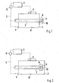
- Fig. 1 is a protective housing 1 for an electric motor 2, which is also the. Stator of this engine itself, provided with flushing holes 3, 4.
- a flushing circuit 5 is connected, in which a monitoring device 6 and a flushing device 7 are arranged.
- the flushing device 7 may comprise a compressed air source, which directs the compressed air through the protective housing 1.
- the protective housing 1 need only be formed so resistant to pressure that it can withstand the compressed air pressure. For this purpose, the protective housing 1 need not be a complex design.
- the monitoring device 6 measures the temperature of the coming out of the protective housing 1 exhaust air and then controls the amount of the protective housing 1 supplied fresh air.
- the flushing device 7 and the monitoring device 6 are outside the potentially explosive environment. The purging takes place in the ex-p-encapsulated space 8.
- a sensor protection housing 9 is fixed with an ex-d-encapsulated space 10 which is sealed against the ex-p-encapsulated space 8.
- the encoder protection housing 9 is a small, stable housing which is pressure-resistant. It is provided in a manner not shown with known columns.
- the encoder guard housing 9 and the gaps are formed such that the encoder guard housing 9 sustains an explosion within the space 10, the gaps causing the explosion wave to dead.
- a transmitter 11 is arranged, which is coupled to the motor shaft.
- the transmitter 11 is advantageously a simple and inexpensive standard design that does not need to be designed for the requirements of explosion protection per se.
- FIG. 2 shows a second embodiment of the protective device according to the invention for an electric motor 2.
- the protective housing 1 'with the connected rinsing circuit is similar to that in Fig. 1 is formed. Also similar to FIG. 1, the encoder protection housing 9 is formed with the transmitter 11. It is different that the encoder protective housing 9 is disposed within the protective housing 1 'in the ex-p-encapsulated space 8'.
Landscapes
- Engineering & Computer Science (AREA)
- Power Engineering (AREA)
- Microelectronics & Electronic Packaging (AREA)
- Motor Or Generator Frames (AREA)
- Control Of Direct Current Motors (AREA)
- Protection Of Generators And Motors (AREA)
- Control Of Electric Motors In General (AREA)
- Control Of Multiple Motors (AREA)
Abstract
Description
- Die Erfindung betrifft eine Vorrichtung für den Explosionsschutz von Elektromotoren oder ähnlichen elektrischen Geräten, wie Pumpen, bei denen der Motor ein Schutzgehäuse aufweist und mit einem mit ihm gekoppelten, in einem Schutzgehäuse untergebrachten Messwertgeber zusammenarbeitet.
- Solche elektrischen Geräte, insbesondere Motoren, müssen für verschiedene Umgebungsbereiche einen Schutz gegen Explosionen aufweisen, damit Personen und Objekte vor Beschädigung geschützt werden. Für Elektromotoren sind gemäß der DIN-Norm EN 50014 verschiedene Schutzklassen für verschiedene Umgebungsbereiche vorgeschrieben, beispielsweise die niedrige Schutzklasse ex-p und die benachbarte, höhere Schutzklasse ex-d. Der Messwertgeber kann
zu verschiedenen Zwecken dienen, beispielsweise zur Positionsinformation für den Motor an sich bzw. für den Rotor, zur Regelung der Drehgeschwindigkeit des Motors usw. - Die Schutzklasse ex-p schreibt vor, dass das Motorschutzgehäuse und das Geberschutzgehäuse nur überdruckfest auszubilden sind, wobei geeignete Spülmaßnahmen durchgeführt werden müssen. Die überdruckfest ausgebildeten Schutzgehäuse müssen dabei mit Spülöffnungen versehen sein, an die sowohl für das Motorschutzgehäuse als auch für das Geberschutzgehäuse jeweils ein eigener, überwachter Spülkreislauf mit einer Überwachungsvorrichtung und einem Spülgerät angeschlossen ist.
- Die Schutzklasse ex-d schreibt vor, dass das Motorschutzgehäuse und das Geberschutzgehäuse druckfest auszubilden sind, wobei der Messwertgeber selbst explosionsfest ausgeführt sein muss. Wenn - in diesen Schutzgehäusen ein zündfähiges Gasgemisch explodiert, müssen die Schutzgehäuse so druckbelastbar sein, dass sie der Explosion im Inneren standhalten, ohne dass ein zündfähiges Gasgemisch außerhalb dieser Schutzgehäuse gezündet wird. Spülkreisläufe sind hier nicht erforderlich.
- In der Schutzklasse ex-p werden somit zwei Spülkreisläufe mit den entsprechenden Vorrichtungen und ein explosionsgeschützter Geber erforderlich, wodurch erhebliche Kosten für den Schutz aufgewandt werden müssen. In der Schutz-klasse ex-d werden hochwertige Schutzgehäuse und ebenfalls ein explosionsgeschützter Geber erforderlich, so dass ebenfalls erhebliche Kosten für den Schutz entstehen.
- Die Aufgabe der Erfindung besteht darin, eine Schutzvorrichtung gemäß dem Oberbegriff des Anspruchs 1 zu schaffen, bei der ein zuverlässiger Explosionsschutz mit möglichst geringem Kostenaufwand erreicht wird.
- Diese Aufgabe wird mit den Merkmalen des Anspruchs 1 gelöst. Hierbei ist vorgesehen, dass das Motorschutzgehäuse und Geberschutzgehäuse für verschieden hohe Schutzklassen ausgebildet sind, wobei für das Motorschutzgehäuse die niedrigere Schutzklasse und für das Geberschutzgehäuse die höhere Schutz-klasse vorgesehen ist und die Schutzvorrichtung für die niedrigere Schutzklasse vorgesehen ist.
- Damit sind nur ein relativ preisgünstiges Motorschutzgehäuse mit nur einem Spülkreislauf und ein druckfestes Geberschutzgehäuse erforderlich, wobei ein preisgünstiger Standartmesswertgeber einsetzbar ist.
- Eine weitere, zweckmäßige Ausbildung der Erfindung sieht vor, dass das Motorschutzgehäuse überdruckfest ausgebildet und mit Spülbohrungen versehen ist und dass das Geberschutzgehäuse druckfest ohne Spüleinrichtung ausgebildet ist.
- Gemäß einer weiteren, vorteilhaften Ausbildung der Erfindung ist das Geberschutzgehäuse mit Spalten zum Abbau einer Explosionswelle versehen.
- Gemäß einer weiteren vorteilhaften Ausbildung der Erfindung ist das Geberschutzgehäuse mit dem Messwertgeber außen am Motorschutzgehäuse angeordnet.
- Gemäß einer alternativen vorteilhaften Ausbildung der Erfindung ist das Geberschutzgehäuse mit dem Messwertgeber im Inneren des Motorschutzgehäuses angeordnet.
- Eine weitere vorteilhafte Maßnahme für einen preisgünstigen Aufbau besteht darin, dass als Messwertgeber ein einfacher Standartgeber eingesetzt ist, der an sich keine Explosionsschutzvorkehrungen aufweist.
- Zu einer zuverlässigen Funktion tragen die Maßnahmen bei, dass an die Spülbohrungen ein überwachter Spülmittelkreislauf mit einer Überwachungsvorrichtung und einem Spülgerät angeschlossen ist.
- Die Erfindung wird nun anhand von Ausführungsbeispielen näher erläutert. Es zeigen:
- Fig. 1 eine Prinzipdarstellung einer Schutzvorrichtung für einen Elektromotor mit daran angeordnetem Messwertgeber nach einem der ersten Ausführungsbeispiele der Erfindung und
- Fig. 2 eine Prinzipdarstellung einer Schutzvorrichtung für einen Elektromotor mit daran angeordneten Messwertgeber nach einem weiteren Ausführungsbeispiel der Erfindung.
- In Fig. 1 ist ein Schutzgehäuse 1 für einen Elektromotor 2, das auch der. Stator dieses Motors selbst sein kann, mit Spülbohrungen 3, 4 versehen. An diese Spülbohrungen 3, 4 ist ein Spülkreislauf 5 angeschlossen, in dem eine Überwachungsvorrichtung 6 und ein Spülgerät 7 angeordnet sind. Das Spülgerät 7 kann eine Pressluftquelle umfassen, die die Pressluft durch das Schutzgehäuse 1 leitet. Das Schutzgehäuse 1 braucht nur so druckfest ausgebildet sein, dass es den Pressluftdruck aushält. Zu diesem Zweck braucht das Schutzgehäuse 1 keine aufwändige Ausführung zu sein. Die Überwachungsvorrichtung 6 misst die Temperatur der aus dem Schutzgehäuse 1 kommenden Abluft und regelt danach die Menge der dem Schutzgehäuse 1 zugeführten Frischluft. Das Spülgerät 7 und die Überwachungsvorrichtung 6 liegen außerhalb des explosionsgefährdeten Umgebungsbereichs. Die Spülung findet in dem ex-p-gekapselten Raum 8 statt.
- An dem Schutzgehäuse 1 bzw. an dem Motor 2 ist ein Geberschutzgehäuse 9 mit einem ex-d-gekapselten Raum 10 befestigt, der gegen den ex-p-gekapselten Raum 8 abgedichtet ist. Das Geberschutzgehäuse 9 ist ein kleines, stabiles Gehäuse, das druckfest ausgebildet ist. Es ist in nicht dargestellter Weise mit bekannten Spalten versehen. Das Geberschutzgehäuse 9 und die Spalte sind derart ausgebildet, dass das Geberschutzgehäuse 9 eine Explosion innerhalb des Raums 10 aushält, wobei die Spalte dafür sorgen, dass sich die Explosionswelle totläuft. Innerhalb des Geberschutzgehäuses 9 ist ein Messwertgeber 11 angeordnet, der mit der Motorwelle gekoppelt ist. Der Messwertgeber 11 ist vorteilhaft eine einfache und preiswerte Standardausführung, die an sich nicht für die Erfordernisse eines Explosionsschutzes ausgelegt zu sein braucht.
- In Fig. 2 ist eine zweite Ausführung' der Schutzvorrichtung gemäß der Erfindung für einen Elektromotor 2 gezeigt. Das Schutzgehäuse 1' mit dem angeschlossenen Spülkreislauf ist ähnlich wie in Fig. 1 ausgebildet. Ebenfalls ähnlich zur Fig. 1 ist das Geberschutzgehäuse 9 mit dem Messwertgeber 11 ausgebildet. Unter-schiedlich ist, dass das Geberschutzgehäuse 9 innerhalb des Schutzgehäuses 1' in dem ex-p-gekapselten Raum 8' angeordnet ist.
Claims (7)
- Vorrichtung für den Explosionsschutz von Elektromotoren oder ähnlichen elektrischen Geräten, wie Pumpen, bei denen der Motor ein Schutzgehäuse aufweist und mit einem mit ihm gekoppelten, in einem eigenen Schutzgehäuse untergebrachten Messwertgeber zusammenarbeitet,
dadurch gekennzeichnet,
dass das Motorschutzgehäuse (1, 1') und das Geberschutzgehäuse (9) für verschieden hohe Schutzklassen ausgebildet sind, wobei für das Motorschutzgehäuse (1, 1') die niedrigere Schutzklasse (ex-p) und für das Geberschutzgehäuse (9) die höhere Schutzklasse (ex-d) vorgesehen ist und die Schutzvorrichtung für die niedrigere Schutzklasse (ex-p) vorgesehen ist. - Vorrichtung nach Anspruch 1,
dadurch gekennzeichnet,
dass das Motorschutzgehäuse (1, 1') überdruckfest ausgebildet und mit Spülbohrungen (3, 4) versehen ist und
dass das Geberschutzgehäuse (9) druckfest ohne Spülbohrungen ausgebildet ist. - Vorrichtung nach Anspruch 1 oder 2,
dadurch gekennzeichnet,
dass das Geberschutzgehäuse (9) mit Spalten zum Abbau einer Explosionswelle versehen ist. - Vorrichtung nach einem der vorhergehenden Ansprüche,
dadurch gekennzeichnet,
dass das Geberschutzgehäuse (9) mit dem Messwertgeber außen am Motorschutzgehäuse (1) angeordnet ist. - Vorrichtung nach einem der Ansprüche 1 bis 3,
dadurch gekennzeichnet,
dass das Geberschutzgehäuse (9) mit dem Messwertgeber im Inneren des Motorschutzgehäuses (1') angeordnet ist. - Vorrichtung nach einem der vorhergehenden Ansprüche,
dadurch gekennzeichnet,
dass als Messwertgeber (11) ein einfacher Standardgeber eingesetzt ist, der an sich keine Explosionsschutzvorrichtung aufweist. - Vorrichtung nach einem der Ansprüche 2 bis 6,
dadurch gekennzeichnet,
dass an die Spülbohrungen (3,4) ein überwachter Spülmittelkreislauf (5) mit einer Überwachungsvorrichtung und einem Spülgerät (7) angeschlossen ist.
Applications Claiming Priority (1)
| Application Number | Priority Date | Filing Date | Title |
|---|---|---|---|
| DE102005012250A DE102005012250A1 (de) | 2005-03-15 | 2005-03-15 | Vorrichtung für den Schutz von Elektromotoren |
Publications (2)
| Publication Number | Publication Date |
|---|---|
| EP1703616A1 true EP1703616A1 (de) | 2006-09-20 |
| EP1703616B1 EP1703616B1 (de) | 2008-09-03 |
Family
ID=36168472
Family Applications (1)
| Application Number | Title | Priority Date | Filing Date |
|---|---|---|---|
| EP06001899A Expired - Lifetime EP1703616B1 (de) | 2005-03-15 | 2006-01-31 | Vorrichtung für den Schutz von Elektromotoren |
Country Status (7)
| Country | Link |
|---|---|
| US (1) | US7460022B2 (de) |
| EP (1) | EP1703616B1 (de) |
| JP (1) | JP5026714B2 (de) |
| AT (1) | ATE407471T1 (de) |
| DE (2) | DE102005012250A1 (de) |
| DK (1) | DK1703616T3 (de) |
| ES (1) | ES2310866T3 (de) |
Cited By (3)
| Publication number | Priority date | Publication date | Assignee | Title |
|---|---|---|---|---|
| FR3002294A1 (fr) * | 2013-02-18 | 2014-08-22 | Ct Xpert Sas | Agencement pour la mise en surpression d'un ensemble electromecanique, une methode d'assemblage et des systemes associes en vue d'exploiter l'ensemble en zone explosible |
| CN105207420A (zh) * | 2015-09-28 | 2015-12-30 | 无锡市南方防爆电机有限公司 | 一种温度检测防暴电机 |
| CN110600227A (zh) * | 2019-11-06 | 2019-12-20 | 新昌灵思变压器科技有限公司 | 一种变压器内部电路自动保护装置 |
Families Citing this family (1)
| Publication number | Priority date | Publication date | Assignee | Title |
|---|---|---|---|---|
| DE102015201411A1 (de) | 2015-01-28 | 2016-07-28 | Robert Bosch Gmbh | Motor-Pumpen-Aggregat für ein Bremssystem |
Citations (4)
| Publication number | Priority date | Publication date | Assignee | Title |
|---|---|---|---|---|
| DE2635553A1 (de) * | 1976-08-06 | 1978-02-09 | Loher Gmbh | Elektromotoren in zuendschutzart d druckfeste kapselung |
| DE3420393A1 (de) * | 1984-06-01 | 1985-12-05 | Gebr. Eickhoff Maschinenfabrik U. Eisengiesserei Mbh, 4630 Bochum | Gleichstrommotor fuer gewinnungsmaschinen des untertagebergbaues, insbesondere fuer walzenschraemmaschinen |
| DE3804602A1 (de) * | 1988-02-13 | 1989-08-24 | Klein Schanzlin & Becker Ag | Explosionsgeschuetzter spaltrohrmotor |
| DE10145521A1 (de) * | 2001-09-11 | 2003-07-17 | Rag Ag | Kühlung für einen Elektromotor |
Family Cites Families (11)
| Publication number | Priority date | Publication date | Assignee | Title |
|---|---|---|---|---|
| DE6906000U (de) * | 1969-02-14 | 1970-02-26 | Bbc Brown Boveri & Cie | Schlagwettergeschuetzte oder explosionsgeschuetzte elektrische maschine |
| US3978877A (en) * | 1974-09-03 | 1976-09-07 | Halliburton Company | Method and apparatus for monitoring and controlling the composition of flammable gas mixtures |
| US4807354A (en) * | 1985-09-10 | 1989-02-28 | General Electric Company | Method of rearranging components of a dynamoelectric machine |
| US5192194A (en) * | 1991-04-23 | 1993-03-09 | Air Engineers, Inc. | Explosion proof compressor and a method for explosion proofing a compressor |
| JPH05137289A (ja) | 1991-11-13 | 1993-06-01 | Fuji Electric Co Ltd | 回転速度検出装置付き耐圧防爆形回転電機 |
| DE4418158C5 (de) * | 1994-05-25 | 2004-03-25 | Hans Peter Dipl.-Ing. Gönnheimer | Vorrichtung zum Betreiben von elektrischen Geräten in einer zündfähigen Atmosphäre |
| EP2270446A1 (de) * | 1998-03-17 | 2011-01-05 | Endress + Hauser GmbH + Co. KG | Elektronisches Gerät für den Einsatz in explosionsgefährdeten Bereichen |
| US7098779B2 (en) * | 2003-02-27 | 2006-08-29 | International Engine Intellectual Property Company, Llc | Method of providing notification of an air intake restriction |
| DE20314330U1 (de) * | 2003-04-15 | 2003-12-11 | Schischek, Alexander | Antrieb, insbesondere Stell- und Regelantrieb, für Klappen und Armaturen |
| US7062952B2 (en) * | 2003-05-21 | 2006-06-20 | General Electric Company | Combustible gas detector having flow-through sensor container and method for measuring such gases |
| US20050285464A1 (en) * | 2004-06-28 | 2005-12-29 | Orders Marcus D | Method and apparatus for dissipating shaft charge |
-
2005
- 2005-03-15 DE DE102005012250A patent/DE102005012250A1/de not_active Ceased
-
2006
- 2006-01-31 DK DK06001899T patent/DK1703616T3/da active
- 2006-01-31 DE DE502006001464T patent/DE502006001464D1/de not_active Expired - Lifetime
- 2006-01-31 EP EP06001899A patent/EP1703616B1/de not_active Expired - Lifetime
- 2006-01-31 AT AT06001899T patent/ATE407471T1/de active
- 2006-01-31 ES ES06001899T patent/ES2310866T3/es not_active Expired - Lifetime
- 2006-03-13 US US11/375,712 patent/US7460022B2/en not_active Expired - Fee Related
- 2006-03-14 JP JP2006069170A patent/JP5026714B2/ja not_active Expired - Fee Related
Patent Citations (4)
| Publication number | Priority date | Publication date | Assignee | Title |
|---|---|---|---|---|
| DE2635553A1 (de) * | 1976-08-06 | 1978-02-09 | Loher Gmbh | Elektromotoren in zuendschutzart d druckfeste kapselung |
| DE3420393A1 (de) * | 1984-06-01 | 1985-12-05 | Gebr. Eickhoff Maschinenfabrik U. Eisengiesserei Mbh, 4630 Bochum | Gleichstrommotor fuer gewinnungsmaschinen des untertagebergbaues, insbesondere fuer walzenschraemmaschinen |
| DE3804602A1 (de) * | 1988-02-13 | 1989-08-24 | Klein Schanzlin & Becker Ag | Explosionsgeschuetzter spaltrohrmotor |
| DE10145521A1 (de) * | 2001-09-11 | 2003-07-17 | Rag Ag | Kühlung für einen Elektromotor |
Cited By (4)
| Publication number | Priority date | Publication date | Assignee | Title |
|---|---|---|---|---|
| FR3002294A1 (fr) * | 2013-02-18 | 2014-08-22 | Ct Xpert Sas | Agencement pour la mise en surpression d'un ensemble electromecanique, une methode d'assemblage et des systemes associes en vue d'exploiter l'ensemble en zone explosible |
| CN105207420A (zh) * | 2015-09-28 | 2015-12-30 | 无锡市南方防爆电机有限公司 | 一种温度检测防暴电机 |
| CN110600227A (zh) * | 2019-11-06 | 2019-12-20 | 新昌灵思变压器科技有限公司 | 一种变压器内部电路自动保护装置 |
| CN110600227B (zh) * | 2019-11-06 | 2020-06-02 | 江西恒通电气有限公司 | 一种变压器内部电路自动保护装置 |
Also Published As
| Publication number | Publication date |
|---|---|
| JP2006262692A (ja) | 2006-09-28 |
| JP5026714B2 (ja) | 2012-09-19 |
| DK1703616T3 (da) | 2009-01-12 |
| DE102005012250A1 (de) | 2006-09-21 |
| US7460022B2 (en) | 2008-12-02 |
| US20060275140A1 (en) | 2006-12-07 |
| EP1703616B1 (de) | 2008-09-03 |
| ATE407471T1 (de) | 2008-09-15 |
| DE502006001464D1 (de) | 2008-10-16 |
| ES2310866T3 (es) | 2009-01-16 |
Similar Documents
| Publication | Publication Date | Title |
|---|---|---|
| DE2753145A1 (de) | Elektronisches steuergeraet, insbesondere fuer den anbau am motorblock von kraftfahrzeugen | |
| DE102013222534A1 (de) | Elektromaschine | |
| DE102015201881A1 (de) | Elektrische Verbindungseinrichtung | |
| DE60114066T2 (de) | Mehrstufenraketenmotor mit einer Interstufen-Schutzvorrichtung | |
| EP1703616B1 (de) | Vorrichtung für den Schutz von Elektromotoren | |
| DE3607466A1 (de) | Pumpenaggregat mit einer niveauschalteinrichtung | |
| DE1938299B2 (de) | Antriebsvorrichtung für Hilfseinnch tungen eines Gasturbmenstrahltnebwerks | |
| DE4013032A1 (de) | In einem tank eingebaute, motorbetriebene pumpe | |
| EP1632013B1 (de) | Antrieb, insbesondere stell- und regelantrieb, für klappen und armaturen | |
| DE9014977U1 (de) | Klemmbrettgehäuse im Bausatz zur Anbringung an elektrischen Stellmotoren zur Ventilsteuerung | |
| DE102005037862B3 (de) | Positionssensor | |
| DE102015214787B3 (de) | Elektrischer Verdichter | |
| EP1594576B1 (de) | Filtergebläse für atemschutzmasken oder -hauben | |
| EP2166648A1 (de) | Elektrische Maschine mit druckfest gekapseltem Drehgeber | |
| DE202004018937U1 (de) | Motor mit wellenförmigem Gehäuse | |
| WO1999017430A2 (de) | Elektrische maschine, insbesondere schleifringloser drehstrom-generator | |
| DE567127C (de) | Elektromotor, insbesondere fuer Naehmaschinen und andere Kleinmaschinen, bei dem die Ankerwelle in am Magnetgestell befestigten Endkappen aus Isolierstoff gelagert und das Magnetgestell von einer Isolierhuelle umgeben ist, die von einem Blechmantel geschuetzt wird | |
| DE102018222831A1 (de) | Motoranordnung mit Sensormodul | |
| DE3926653A1 (de) | Hall-effekt-sensoranordnung | |
| DE3837844A1 (de) | Anordnung des stators im motorgehaeuse von elektrowerkzeugen | |
| DE3533750C1 (en) | Explosion-proof and/or flameproof electrical power supply unit having an alternator which is driven by compressed air | |
| DE102010000804A1 (de) | Elektrisches Betriebsmittel mit Überdruckkapselung für explosionsgefährdete Bereiche | |
| DE2712918A1 (de) | Elektrizitaetszaehler mit einem sonderzaehlwerk | |
| DE4130520C2 (de) | Elektronisch kommutierter Gleichstrom-Kleinmotor | |
| DE9400903U1 (de) | Spannungsprüfungseinrichtung |
Legal Events
| Date | Code | Title | Description |
|---|---|---|---|
| PUAI | Public reference made under article 153(3) epc to a published international application that has entered the european phase |
Free format text: ORIGINAL CODE: 0009012 |
|
| AK | Designated contracting states |
Kind code of ref document: A1 Designated state(s): AT BE BG CH CY CZ DE DK EE ES FI FR GB GR HU IE IS IT LI LT LU LV MC NL PL PT RO SE SI SK TR |
|
| AX | Request for extension of the european patent |
Extension state: AL BA HR MK YU |
|
| 17P | Request for examination filed |
Effective date: 20070320 |
|
| 17Q | First examination report despatched |
Effective date: 20070419 |
|
| AKX | Designation fees paid |
Designated state(s): AT BE BG CH CY CZ DE DK EE ES FI FR GB GR HU IE IS IT LI LT LU LV MC NL PL PT RO SE SI SK TR |
|
| GRAP | Despatch of communication of intention to grant a patent |
Free format text: ORIGINAL CODE: EPIDOSNIGR1 |
|
| GRAS | Grant fee paid |
Free format text: ORIGINAL CODE: EPIDOSNIGR3 |
|
| GRAA | (expected) grant |
Free format text: ORIGINAL CODE: 0009210 |
|
| AK | Designated contracting states |
Kind code of ref document: B1 Designated state(s): AT BE BG CH CY CZ DE DK EE ES FI FR GB GR HU IE IS IT LI LT LU LV MC NL PL PT RO SE SI SK TR |
|
| REG | Reference to a national code |
Ref country code: GB Ref legal event code: FG4D Free format text: NOT ENGLISH |
|
| REG | Reference to a national code |
Ref country code: CH Ref legal event code: EP |
|
| REG | Reference to a national code |
Ref country code: CH Ref legal event code: NV Representative=s name: SCINTILLA AG, DIREKTION |
|
| REG | Reference to a national code |
Ref country code: IE Ref legal event code: FG4D Free format text: LANGUAGE OF EP DOCUMENT: GERMAN |
|
| REF | Corresponds to: |
Ref document number: 502006001464 Country of ref document: DE Date of ref document: 20081016 Kind code of ref document: P |
|
| REG | Reference to a national code |
Ref country code: SE Ref legal event code: TRGR |
|
| REG | Reference to a national code |
Ref country code: DK Ref legal event code: T3 |
|
| REG | Reference to a national code |
Ref country code: ES Ref legal event code: FG2A Ref document number: 2310866 Country of ref document: ES Kind code of ref document: T3 |
|
| PG25 | Lapsed in a contracting state [announced via postgrant information from national office to epo] |
Ref country code: LT Free format text: LAPSE BECAUSE OF FAILURE TO SUBMIT A TRANSLATION OF THE DESCRIPTION OR TO PAY THE FEE WITHIN THE PRESCRIBED TIME-LIMIT Effective date: 20080903 |
|
| PG25 | Lapsed in a contracting state [announced via postgrant information from national office to epo] |
Ref country code: SI Free format text: LAPSE BECAUSE OF FAILURE TO SUBMIT A TRANSLATION OF THE DESCRIPTION OR TO PAY THE FEE WITHIN THE PRESCRIBED TIME-LIMIT Effective date: 20080903 Ref country code: LV Free format text: LAPSE BECAUSE OF FAILURE TO SUBMIT A TRANSLATION OF THE DESCRIPTION OR TO PAY THE FEE WITHIN THE PRESCRIBED TIME-LIMIT Effective date: 20080903 Ref country code: FI Free format text: LAPSE BECAUSE OF FAILURE TO SUBMIT A TRANSLATION OF THE DESCRIPTION OR TO PAY THE FEE WITHIN THE PRESCRIBED TIME-LIMIT Effective date: 20080903 |
|
| REG | Reference to a national code |
Ref country code: IE Ref legal event code: FD4D |
|
| PG25 | Lapsed in a contracting state [announced via postgrant information from national office to epo] |
Ref country code: BG Free format text: LAPSE BECAUSE OF FAILURE TO SUBMIT A TRANSLATION OF THE DESCRIPTION OR TO PAY THE FEE WITHIN THE PRESCRIBED TIME-LIMIT Effective date: 20081203 Ref country code: IE Free format text: LAPSE BECAUSE OF FAILURE TO SUBMIT A TRANSLATION OF THE DESCRIPTION OR TO PAY THE FEE WITHIN THE PRESCRIBED TIME-LIMIT Effective date: 20080903 |
|
| PG25 | Lapsed in a contracting state [announced via postgrant information from national office to epo] |
Ref country code: CZ Free format text: LAPSE BECAUSE OF FAILURE TO SUBMIT A TRANSLATION OF THE DESCRIPTION OR TO PAY THE FEE WITHIN THE PRESCRIBED TIME-LIMIT Effective date: 20080903 Ref country code: RO Free format text: LAPSE BECAUSE OF FAILURE TO SUBMIT A TRANSLATION OF THE DESCRIPTION OR TO PAY THE FEE WITHIN THE PRESCRIBED TIME-LIMIT Effective date: 20080903 Ref country code: PT Free format text: LAPSE BECAUSE OF FAILURE TO SUBMIT A TRANSLATION OF THE DESCRIPTION OR TO PAY THE FEE WITHIN THE PRESCRIBED TIME-LIMIT Effective date: 20090203 Ref country code: IS Free format text: LAPSE BECAUSE OF FAILURE TO SUBMIT A TRANSLATION OF THE DESCRIPTION OR TO PAY THE FEE WITHIN THE PRESCRIBED TIME-LIMIT Effective date: 20090103 Ref country code: SK Free format text: LAPSE BECAUSE OF FAILURE TO SUBMIT A TRANSLATION OF THE DESCRIPTION OR TO PAY THE FEE WITHIN THE PRESCRIBED TIME-LIMIT Effective date: 20080903 |
|
| PLBI | Opposition filed |
Free format text: ORIGINAL CODE: 0009260 |
|
| 26 | Opposition filed |
Opponent name: SEW-EURODRIVE GMBH & CO. KG Effective date: 20090525 |
|
| PLAX | Notice of opposition and request to file observation + time limit sent |
Free format text: ORIGINAL CODE: EPIDOSNOBS2 |
|
| PG25 | Lapsed in a contracting state [announced via postgrant information from national office to epo] |
Ref country code: EE Free format text: LAPSE BECAUSE OF FAILURE TO SUBMIT A TRANSLATION OF THE DESCRIPTION OR TO PAY THE FEE WITHIN THE PRESCRIBED TIME-LIMIT Effective date: 20080903 |
|
| PG25 | Lapsed in a contracting state [announced via postgrant information from national office to epo] |
Ref country code: MC Free format text: LAPSE BECAUSE OF NON-PAYMENT OF DUE FEES Effective date: 20090131 |
|
| NLR1 | Nl: opposition has been filed with the epo |
Opponent name: SEW-EURODRIVE GMBH & CO. KG |
|
| PLAF | Information modified related to communication of a notice of opposition and request to file observations + time limit |
Free format text: ORIGINAL CODE: EPIDOSCOBS2 |
|
| REG | Reference to a national code |
Ref country code: FR Ref legal event code: ST Effective date: 20091030 |
|
| PLBB | Reply of patent proprietor to notice(s) of opposition received |
Free format text: ORIGINAL CODE: EPIDOSNOBS3 |
|
| PG25 | Lapsed in a contracting state [announced via postgrant information from national office to epo] |
Ref country code: FR Free format text: LAPSE BECAUSE OF NON-PAYMENT OF DUE FEES Effective date: 20090202 |
|
| PG25 | Lapsed in a contracting state [announced via postgrant information from national office to epo] |
Ref country code: PL Free format text: LAPSE BECAUSE OF FAILURE TO SUBMIT A TRANSLATION OF THE DESCRIPTION OR TO PAY THE FEE WITHIN THE PRESCRIBED TIME-LIMIT Effective date: 20080903 |
|
| PG25 | Lapsed in a contracting state [announced via postgrant information from national office to epo] |
Ref country code: GR Free format text: LAPSE BECAUSE OF FAILURE TO SUBMIT A TRANSLATION OF THE DESCRIPTION OR TO PAY THE FEE WITHIN THE PRESCRIBED TIME-LIMIT Effective date: 20081204 |
|
| PG25 | Lapsed in a contracting state [announced via postgrant information from national office to epo] |
Ref country code: LU Free format text: LAPSE BECAUSE OF NON-PAYMENT OF DUE FEES Effective date: 20090131 |
|
| PG25 | Lapsed in a contracting state [announced via postgrant information from national office to epo] |
Ref country code: HU Free format text: LAPSE BECAUSE OF FAILURE TO SUBMIT A TRANSLATION OF THE DESCRIPTION OR TO PAY THE FEE WITHIN THE PRESCRIBED TIME-LIMIT Effective date: 20090304 |
|
| PG25 | Lapsed in a contracting state [announced via postgrant information from national office to epo] |
Ref country code: TR Free format text: LAPSE BECAUSE OF FAILURE TO SUBMIT A TRANSLATION OF THE DESCRIPTION OR TO PAY THE FEE WITHIN THE PRESCRIBED TIME-LIMIT Effective date: 20080903 |
|
| PG25 | Lapsed in a contracting state [announced via postgrant information from national office to epo] |
Ref country code: CY Free format text: LAPSE BECAUSE OF FAILURE TO SUBMIT A TRANSLATION OF THE DESCRIPTION OR TO PAY THE FEE WITHIN THE PRESCRIBED TIME-LIMIT Effective date: 20080903 |
|
| PLCK | Communication despatched that opposition was rejected |
Free format text: ORIGINAL CODE: EPIDOSNREJ1 |
|
| PLBN | Opposition rejected |
Free format text: ORIGINAL CODE: 0009273 |
|
| STAA | Information on the status of an ep patent application or granted ep patent |
Free format text: STATUS: OPPOSITION REJECTED |
|
| 27O | Opposition rejected |
Effective date: 20110914 |
|
| REG | Reference to a national code |
Ref country code: DE Ref legal event code: R100 Ref document number: 502006001464 Country of ref document: DE Effective date: 20110914 |
|
| PGFP | Annual fee paid to national office [announced via postgrant information from national office to epo] |
Ref country code: DK Payment date: 20120125 Year of fee payment: 7 Ref country code: BE Payment date: 20120123 Year of fee payment: 7 Ref country code: SE Payment date: 20120124 Year of fee payment: 7 Ref country code: IT Payment date: 20120126 Year of fee payment: 7 |
|
| PGFP | Annual fee paid to national office [announced via postgrant information from national office to epo] |
Ref country code: NL Payment date: 20120127 Year of fee payment: 7 |
|
| PGFP | Annual fee paid to national office [announced via postgrant information from national office to epo] |
Ref country code: AT Payment date: 20120123 Year of fee payment: 7 |
|
| PGFP | Annual fee paid to national office [announced via postgrant information from national office to epo] |
Ref country code: CH Payment date: 20130123 Year of fee payment: 8 Ref country code: ES Payment date: 20130122 Year of fee payment: 8 Ref country code: GB Payment date: 20130122 Year of fee payment: 8 |
|
| BERE | Be: lapsed |
Owner name: BOSCH REXROTH A.G. Effective date: 20130131 |
|
| REG | Reference to a national code |
Ref country code: NL Ref legal event code: V1 Effective date: 20130801 |
|
| REG | Reference to a national code |
Ref country code: DK Ref legal event code: EBP |
|
| REG | Reference to a national code |
Ref country code: AT Ref legal event code: MM01 Ref document number: 407471 Country of ref document: AT Kind code of ref document: T Effective date: 20130131 |
|
| REG | Reference to a national code |
Ref country code: SE Ref legal event code: EUG |
|
| PG25 | Lapsed in a contracting state [announced via postgrant information from national office to epo] |
Ref country code: SE Free format text: LAPSE BECAUSE OF NON-PAYMENT OF DUE FEES Effective date: 20130201 Ref country code: BE Free format text: LAPSE BECAUSE OF NON-PAYMENT OF DUE FEES Effective date: 20130131 Ref country code: AT Free format text: LAPSE BECAUSE OF NON-PAYMENT OF DUE FEES Effective date: 20130131 Ref country code: NL Free format text: LAPSE BECAUSE OF NON-PAYMENT OF DUE FEES Effective date: 20130801 |
|
| PG25 | Lapsed in a contracting state [announced via postgrant information from national office to epo] |
Ref country code: IT Free format text: LAPSE BECAUSE OF NON-PAYMENT OF DUE FEES Effective date: 20130131 |
|
| PG25 | Lapsed in a contracting state [announced via postgrant information from national office to epo] |
Ref country code: DK Free format text: LAPSE BECAUSE OF NON-PAYMENT OF DUE FEES Effective date: 20130131 |
|
| REG | Reference to a national code |
Ref country code: CH Ref legal event code: PL |
|
| GBPC | Gb: european patent ceased through non-payment of renewal fee |
Effective date: 20140131 |
|
| PG25 | Lapsed in a contracting state [announced via postgrant information from national office to epo] |
Ref country code: LI Free format text: LAPSE BECAUSE OF NON-PAYMENT OF DUE FEES Effective date: 20140131 Ref country code: CH Free format text: LAPSE BECAUSE OF NON-PAYMENT OF DUE FEES Effective date: 20140131 |
|
| PG25 | Lapsed in a contracting state [announced via postgrant information from national office to epo] |
Ref country code: GB Free format text: LAPSE BECAUSE OF NON-PAYMENT OF DUE FEES Effective date: 20140131 |
|
| REG | Reference to a national code |
Ref country code: ES Ref legal event code: FD2A Effective date: 20150731 |
|
| PG25 | Lapsed in a contracting state [announced via postgrant information from national office to epo] |
Ref country code: ES Free format text: LAPSE BECAUSE OF NON-PAYMENT OF DUE FEES Effective date: 20140201 |
|
| PGFP | Annual fee paid to national office [announced via postgrant information from national office to epo] |
Ref country code: DE Payment date: 20210323 Year of fee payment: 16 |
|
| REG | Reference to a national code |
Ref country code: DE Ref legal event code: R119 Ref document number: 502006001464 Country of ref document: DE |
|
| PG25 | Lapsed in a contracting state [announced via postgrant information from national office to epo] |
Ref country code: DE Free format text: LAPSE BECAUSE OF NON-PAYMENT OF DUE FEES Effective date: 20220802 |