EP1703228A1 - Baueinheit für eine Kompaktheizungsanlage - Google Patents
Baueinheit für eine Kompaktheizungsanlage Download PDFInfo
- Publication number
- EP1703228A1 EP1703228A1 EP05005571A EP05005571A EP1703228A1 EP 1703228 A1 EP1703228 A1 EP 1703228A1 EP 05005571 A EP05005571 A EP 05005571A EP 05005571 A EP05005571 A EP 05005571A EP 1703228 A1 EP1703228 A1 EP 1703228A1
- Authority
- EP
- European Patent Office
- Prior art keywords
- positive
- assembly
- assembly according
- locking element
- locking
- Prior art date
- Legal status (The legal status is an assumption and is not a legal conclusion. Google has not performed a legal analysis and makes no representation as to the accuracy of the status listed.)
- Granted
Links
- 238000010438 heat treatment Methods 0.000 title claims abstract description 23
- 238000009434 installation Methods 0.000 title 1
- 238000002347 injection Methods 0.000 claims abstract description 11
- 239000007924 injection Substances 0.000 claims abstract description 11
- 230000005540 biological transmission Effects 0.000 claims abstract description 4
- 239000012530 fluid Substances 0.000 claims abstract description 3
- 230000002349 favourable effect Effects 0.000 description 3
- 238000003780 insertion Methods 0.000 description 3
- 230000037431 insertion Effects 0.000 description 3
- 238000013461 design Methods 0.000 description 2
- JEIPFZHSYJVQDO-UHFFFAOYSA-N iron(III) oxide Inorganic materials O=[Fe]O[Fe]=O JEIPFZHSYJVQDO-UHFFFAOYSA-N 0.000 description 2
- 238000000034 method Methods 0.000 description 2
- 230000001953 sensory effect Effects 0.000 description 2
- XLYOFNOQVPJJNP-UHFFFAOYSA-N water Substances O XLYOFNOQVPJJNP-UHFFFAOYSA-N 0.000 description 2
- 230000007547 defect Effects 0.000 description 1
- 238000010348 incorporation Methods 0.000 description 1
- 238000012423 maintenance Methods 0.000 description 1
- 238000012549 training Methods 0.000 description 1
- 238000013519 translation Methods 0.000 description 1
Images



Classifications
-
- F—MECHANICAL ENGINEERING; LIGHTING; HEATING; WEAPONS; BLASTING
- F24—HEATING; RANGES; VENTILATING
- F24H—FLUID HEATERS, e.g. WATER OR AIR HEATERS, HAVING HEAT-GENERATING MEANS, e.g. HEAT PUMPS, IN GENERAL
- F24H9/00—Details
- F24H9/14—Arrangements for connecting different sections, e.g. in water heaters
-
- F—MECHANICAL ENGINEERING; LIGHTING; HEATING; WEAPONS; BLASTING
- F24—HEATING; RANGES; VENTILATING
- F24H—FLUID HEATERS, e.g. WATER OR AIR HEATERS, HAVING HEAT-GENERATING MEANS, e.g. HEAT PUMPS, IN GENERAL
- F24H9/00—Details
- F24H9/14—Arrangements for connecting different sections, e.g. in water heaters
- F24H9/142—Connecting hydraulic components
Definitions
- the invention relates to a structural unit for a compact heating system with the features specified in the preamble of claim 1.
- Such units are today known in the art and usually consist of two or more plastic injection molded components, which record all major hydraulic and sensory components of a compact heating system in addition to a circulating pump and the plate plate heat exchanger usually connected at the back.
- the assembly is designed so that it can be largely factory prefabricated and on site by the heating engineer with the least possible effort reliably and quickly mounted.
- the stationary lines - these are typically two lines for the space heating heating circuit and a line for hot water supply and another line for the heated service water - with the unit, it is bekonnt, the stationary lines in an example attached to the wall chassis form the compact heating system in the form of plug-in connections, on which then the unit is plugged with their correspondingly shaped connections.
- the invention has the object, a generic unit in such a way that it can be easily, quickly and reliably connected within the compact heating system, mounted and secured.
- the structural unit according to the invention consists of a one-part or multi-part injection molded housing and has pluggable line connections, via which the conductive connection to the corresponding stationary fluid lines takes place.
- the connector and the assembly within the compact heating system is secured by positive locking means, but not, as in the prior art by a separate fuse element in the form of a screw, but by a movable mounted on the unit form-locking element, with a kompaktsammlungungsanlagen remedy component, usually the Chassis desken connection plate by engaging behind the form-fitting Fuse forms.
- the basic idea of the present invention is therefore not to use a separate securing element here, but to provide a positive locking element on the structural unit and to mount it in such a movable manner that it can be brought into an interlocking position after the plug connection has been formed. This can be done either by moving the Formschtussetementes or by turning the same, depending on the design of the positive connection.
- gear unit means for moving the positive-locking element are particularly advantageously provided on the structural unit. This can be done to facilitate the accessibility of the actuator, but also with a suitable translation to increase the actuating forces.
- the transmission means can be advantageously designed so that self-locking occurs, d. h. That the one or more positive locking elements remain in their locked position ver and can not be inadvertently solved by external force.
- additional forces can be used up in the insertion direction in order to ensure the intended positioning of the structural unit within the compact heating system.
- the one or more positive locking elements are mounted in a translationally movable manner, so that they secure the connection in a bolt-like manner after the fluid-conducting connections have been plugged together.
- the transiatory movement of the form-locking elements or the form-locking element, if only one is provided advantageously transversely to the direction of insertion of the terminal, since particularly high forces are absorbed in this arrangement can, without the risk of loosening the Form gleichver connection is given.
- the Fvrm gleichelement is arranged directly on a rack, which is guided displaceably in or on the assembly, with this rack, a drive wheel is engaged, which is rotatably mounted in or on the assembly. Then, the translational movement, with which the rack and the attached form-locking element is moved for the purpose of locking, take place via a rotational movement of the drive wheel, whereby only a small space for generating this translational movement is required, but at the same time with appropriate dimensioning comparatively high forces can also be applied by hand.
- the interlocking element does not necessarily have to be attached directly to the rack, it is also an indirect connection conceivable in which the rack drives a further component, which carries the ForrnMedicelement.
- locking means are provided, which secures the Form gleichelernent in the locking position, so that accidentally does not unintentionally cancel the positive engagement due to external forces, without this being desirable.
- a rust position can be provided both in the drive means and in the region of the positive-locking element. It is expediently designed so that the rust process is both audible and palpable upon actuation, so that the installer of the unit quasi a mechanical and audible feedback received as soon as the lock is located in the intended position.
- connection plate can form part of the chassis of the compact heating system, wherein for each positive locking element expediently a recess is provided in this connection plate, through which the plug-in unit on the plate, the respective form-fitting element is inserted, such that the positive locking element engages behind the connection plate after locking and thus the unit on the connection plate and thus the chassis of the compact heating system positively secures and at the same time the line connections, which are designed as plug-in connections.
- the positive-locking element has an oblique surface directed towards the connecting plate, which pulls the structural unit toward the plate when it is moved into the locking position. In this way, at the same time with the locking an additional force in the insertion direction be applied, which causes an intimate connection of the assembly with the terminal plate and the terminals located thereon of the stationary lines.
- the drive wheel which causes the translational movement of the rack, part of a shaft which is rotatably mounted within the assembly.
- the drive wheel and shaft are advantageously integrally formed as a plastic injection molded part and preferably latched in a bearing receptacle of the assembly and rotatably mounted so that after inserting the rack in the unit provided on the linear guide which carries the drive wheel shaft can be inserted into the bearing receptacle, after which Drive connection between the drive wheel and rack is made.
- the drive shaft is expediently provided on the front side with a tool holder, which is preferably arranged so that it is freely accessible even in the installed state of the unit.
- both the backup ie. H. the locking of the connector and in the event of a later error or defect the Entsichem be solved in a simple manner by inserting and rotating the tool.
- the positive-locking element is expediently arranged on the underside of the toothed rack, and at a distance therefrom via a web, which produces the connection between the structural unit and the positive-locking element.
- each of the laterally adjoining housing parts associated with a movably mounted positive-locking element.
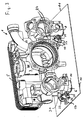
- a part of a compact heating system is shown, namely a structural unit 1, which is formed of three interconnected Sprifizgussgereheat tone 2, 3 and 4.
- the exemplary embodiment stands for a multiplicity of structural units, as used in such compact heating systems Use and is only to be understood as an example, it could be one piece but also more than three parts.
- the housing parts 2 and 3 are connected at the rear to a plate heat exchanger 5, which also connects them mechanically to one another by incorporation of the middle housing part 4.
- the assembly 1 is designed and provided in a conventional manner for receiving almost all hydraulic and sensory components of the compact heating system. It is in this context only as an example to the European Patent Application 03 025 083.1 referenced where the structure and function of such a compact heating system is described in detail.
- the assembly 1 has four downwardly leading line connections 6, 7, 8 and 9, which are provided for connection of the unit 1 with stationary pipelines.
- the stationary lines which are not shown in the drawings, are fixed by means of connecting pieces 10, in a receiving plate 11.
- the receiving plate 11 forms part of the example attached to the wall chassis of the compact heating system, which is not shown here in detail.
- the connecting pieces 10 have on their underside a thread, via which they are connected in a conventional manner with the free ends of the stationary pipes.
- These sockets have previously been inserted from above, ie from the unit side side of the connection plate 11 through oval recesses 14, so that they occupy the position shown in Figures 1 and 2, in which they rest with a flaky part on the top of the receiving plate 11, pass through the respective recess 14 with a positive-locking part and lying behind a groove, with which the connecting pieces 10 by means of a bracket, not shown, can be secured positively within the receiving plate 11 ,
- the connecting pieces 10 have on the receiving plate 11 upwardly projecting part a groove 13 which is provided for receiving an O-ring, which seals the respective Anschlußstufizen 10 with this after plugging in the direction 12 cross-pipe connection 6 to 9.
- the connecting pieces 10 are thus arranged in alignment with the line terminals 6 to 9 in corresponding provided in the receiving plate 11 slot-shaped recesses 14 and fixed.
- the assembly 1 which is then advantageously fully populated, lowered in the direction 12 with the line terminals 6 to 9. until the connecting pieces 10 sealingly engage in the line connections 6 to 9.
- plate-shaped form-locking elements 15 pass through approximately T-shaped recesses 16 in the connection plate 11.
- These positive locking elements 15 are connected via a web to the back of a rack 16 and formed integrally therewith, such that a positive locking element 15 laterally projects beyond the web to two directions , as is visible with reference to Figures 4 and 5.
- the two positive locking elements 15 When placing the assembly 1 in the direction 12, the two positive locking elements 15 first pass through the larger rectangular portion of a recess 16. To secure the unit 1 relative to the stationary receiving plate 11 and the line connections 6 to 9 in the connecting piece 10 form fit, then the form-fitting elements 15 translated translationally in the direction 18. As a result, the two form-fitting elements 15 projecting laterally beyond the web reach into the region next to a recess 16, in which they are still covered by parts 19 of the receiving plate at the top. whereby a positive connection opposite the mounting direction 12 is achieved.
- the structural unit 1 is pulled in the direction of the connecting plate 11 when the interlocking elements 15 move in the direction of the connecting elements 11, since the interlocking elements 15 are attached to the rear side of the respective toothed rack 7, which in turn is only in the structural unit 1 is mounted displaceably in the direction 18 and the opposite direction.
- a bearing receptacle 21 is provided, in which not only the rack 17 is displaceably guided, but in the beyond a shaft 22 is rotatably mounted, which carries a drive wheel 23, which in built Condition meshes with the rack 17 and this form-fitting secured within the bearing seat 21.
- the bearing holder 21 thus forms a linear guide for the rack 17 and a bearing for the shaft 22. Since the bearing receptacle 21 is arranged between each two line connections 6, 7, 8, 9, this can absorb high forces, since the unit 1 in the area the line connections has a particularly high stability.
- ribs 24 are additionally provided on the right-hand injection-molded housing part 3, which additionally reinforce or support the bearing mount 21.
- the shaft 22 is formed with a tool holder 25 in the form of a hexagon socket. It also has on its outer circumference a radial projection 26 which on the one hand forms a stop for the shaft 22 inserted in the bearing receptacle 21 in terms of its rotational movement and on the other part can form a latching connection with appropriate training the axial guide track on the outside of the bearing seat 21 (FIG. 5).
- a grate connection in which the projection 26 is guided in a corresponding recess.
- the shaft 22 with the drive wheel 23, the projection 26 and the molded tool holder 25 is integrally formed as a plastic injection molded part.
- the pointing in Fig. 5 in the plane of the drawing end is conical and longitudinally divided, so that this component in the corresponding circular recess 27 of the bearing holder 21 is inserted in such a way that it there after reaching its intended position by cushioning the end-side divided area locked.
- a further latching connection between the free end of the rack 17 and the recess 16 is provided in the embodiment of FIG. 5 is extended to the opposite direction 18 for this purpose
- Part of the rack 17 on the underside a locking lug 28 is provided, which then, when the interlocking elements 15 are arranged completely below the parts 19 of the receiving plate 11, audibly and tangibly engages in the recess 16, so that the fitter knows that the locked position is reached.
- This locking lug 28 also secures the lock against unintentional release.
- the detent nose 28 ' is modified.
- the end of the rack 17 is wave-shaped, whereby on the one hand a greater travel of the locking lug 28 'is achieved and on the other hand at the end of a handle 29 is formed, which serves to release the latching connection, when the lock should be canceled, for example the unit 1 of the receiving plate 11 for the purpose of repair or maintenance to separate.
- This handle 29 allows the detent 28 'manually or by means of a tool so far from the recess 16 lift up that the shaft 22 can be rotated so that the rack 17 moves in the opposite direction to the direction 18, then, if the respective form-fit element 15 with the larger part of the recess 16 is aligned with the entire assembly 1 against the direction 12 to pull upwards.
- a circular recess 30 is provided within the receiving plate 12, in which engages a projecting at the middle injection molded part 4 downwardly conical nose 31 after lowering the assembly 1 in the direction 12.
- the middle housing part 4 is supported and also facilitates the placement of the assembly 1 on the receiving plate 11, as done by the conical nose 31, a guide and centering of the assembly 1 to the plate 11.
Landscapes
- Engineering & Computer Science (AREA)
- General Engineering & Computer Science (AREA)
- Chemical & Material Sciences (AREA)
- Thermal Sciences (AREA)
- Combustion & Propulsion (AREA)
- Mechanical Engineering (AREA)
- Physics & Mathematics (AREA)
- Injection Moulding Of Plastics Or The Like (AREA)
- Pipe Accessories (AREA)
- Instantaneous Water Boilers, Portable Hot-Water Supply Apparatuses, And Control Of Portable Hot-Water Supply Apparatuses (AREA)
- Air-Conditioning For Vehicles (AREA)
- Basic Packing Technique (AREA)
- Yarns And Mechanical Finishing Of Yarns Or Ropes (AREA)
- Resistance Heating (AREA)
Abstract
Description
- Die Erfindung betrifft eine Baueinheit für eine Kompaktheizungsanlage mit den im Oberbegriff des Anspruchs 1 angegebenen Merkmalen. Derartige Baueinheiten zöhlen heute zum Stand der Technik und bestehen üblicherweise aus zwei oder mehr Kunststoffspritzgussbauteilen, welche neben einer Umwälzpumpe und dem meist rückseitig angeschlossenen Plattenwärmetauscher alle wesentlichen hydraulischen und sensorischen Bauteile einer Kompaktheizungsanlage aufnehmen. Dabei ist die Baueinheit nach Möglichkeit so konstruiert, dass sie weitgehend fabrikmäßig vorgefertigt werden kann und vor Ort durch den Heizungsmonteur mit möglichst wenigen Handgriffen zuverlässig und schnell montierbar ist.
- Um die ortsfesten Leitungen - dies sind typischerweise zwei Leitungen für den die Raumheizung betreffenden Heizkreis sowie eine Leitung zur Brauchwasserzufuhr und eine weitere Leitung für das erwärmte Brauchwasser - mit der Baueinheit zu verbinden ist es bekonnt, die stationären Leitungen in einem beispielsweise an der Wand befestigten Chassis der Kompaktheizungsanlage in Form von Steckanschlüssen auszubilden, auf die dann die Baueinheit mit ihren entsprechend ausgebildeten Anschlüssen aufgesteckt wird. Um die Baueinheit in dieser mit den stationären Leitungen verbundenen Stellung zu sichern, zählt es zum Stand der Technik, innerhalb der Baueinheit ein oder mehrere Gewindehülsen zu integrieren und diese nach Aufsetzen der Baueinheit von unten durch Schrauben zu sichern, die einerseits am Chassis anliegen und andererseits in den Gewindehülsen der Baueinheit festgelegt sind.
- Zwar hat sich diese Befestigungsmethode grundsätzlich bewährt, da zunächst an der Anschlussplotte des Chassis die ortsfesten Leitungsanschlüsse angebracht werden, wonach die Baueinheit aufgesetzt und dann schließlich durch Schrauben gesichert wird, doch bedingt diese Art der Formschlusssicherung eine Zugänglichkeit von der Unterseite des Chassis her. Hier ist jedoch der Raum üblicherweise allein schon durch die dort vorhandenen Leitungen eng begrenzt. Darüber hinaus können durch die vorgenannten Schraubverbindungen relativ hohe Kräfte aufgebracht werden, was zur punktuellen Überbelastung der Baueinheit führen kann.
- Vor diesem Hintergrund liegt der Erfindung die Aufgabe zugrunde, eine gattungsgemäße Baueinheit so auszubilden, dass sie einfach, schnell und zuverlässig innerhalb der Kompaktheizungsanlage angeschlossen, montiert und gesichert werden kann.
- Diese Aufgabe wird gemäß der Erfindung durch die in Anspruch 1 angegebenen Merkmale gelöst. Vorteilhafte Ausgestaltungen der Erfindung sind in den Unteransprüchen, der nachfolgenden Beschreibung und der Zeichnung angegeben.
- Die erfindungsgemäße Baueinheit besteht aus einem ein- oder mehrteiligen Spritzgussgehäuse und weist steckbare Leitungsanschlüsse auf, über welche die leitende Verbindung zu der entsprechenden ortsfesten Fluidleitungen erfolgt. Dabei ist die Steckverbindung sowie auch die Baueinheit innerhalb der Kompaktheizungsanlage durch Formschlussmittel gesichert, allerdings nicht, wie beim Stand der Technik durch ein gesondertes Sicherungselement in Form einer Schraube, sondern durch ein bewegbar on der Baueinheit gelagertes Formschlusselement, das mit einem kompaktheizungsanlagenseitigen Bauteil, üblicherweise der chassisseitigen Anschlussplatte durch Hintergreifen derselben die formschlüssige Sicherung bildet. Grundgedanke der vorliegenden Erfindung ist es also, hier nicht ein gesondertes sicherungselement einzusetzen, sondern ein Formschlusselement an der Baueinheit vorzusehen und dieses derart bewegbar zu lagern, dass es nach dem Bilden der Steckverbindung in eine verriegelnde Stellung gebracht werden kann. Dies kann entweder durch Verschieben des Formschtussetementes oder auch durch Drehen desselben erfolgen, je nach Ausbildung der Formschlussverbindung.
- Grundsätzlich ist zwar eine unmittelbare Betätigung des Formschlusselementes in seiner Lagerung an der Baueinheit denkbar, besonders vorteilhaft sind jedoch an der Baueinheit Getriebemittel zum Bewegen des Formschlusselementes vorgesehen. Dies kann erfolgen, um die Zugänglichkeit der Betätigung zu erleichtern, aber auch bei geeigneter Übersetzung um die Betätigungskräfte zu erhöhen, Darüber hinaus können die Getriebemittel vorteilhaft so ausgebildet sein, dass selbsthemmung auftritt, d. h., dass das oder die Formschlusselemente in ihrer ver riegelten Stellung verbleiben und sich nicht durch äußere Krafteinwirkung unbeabsichtigt lösen können. Schließlich können bei geeigneter Ausbildung der Formschlusselemente zusätzlich noch Kräfte in Einsteckrichtung aufgebraucht werden, um die bestimmungsgemäBe Positionierung der Baueinheit innerhalb der Kompaktheizungsanlage sicherzustellen.
- Besonders vorteilhaft ist es, wenn das bzw. die Formschlusselemente translatorisch bewegbar gelagert sind, so dass sie nach dem Zusammenstecken der fluidleitenden Verbindungen riegelähnlich die Verbindung sichern. Dabei erfolgt die transiatorische Bewegung der Formschlusselemente bzw. des Formschlusselementes, wenn nur eins vorgesehen ist, zweckmäßigerweise quer zur Steckrichtung des Anschlusses, da bei dieser Anordnung besonders hohe Kräfte aufgenommen werden können, ohne dass die Gefahr des sich Lösens der Formschlussver bindung gegeben ist.
- In einer bevorzugten Ausbildung der Erfindung ist das Fvrmschlusselement unmittelbar an einer Zahnstange angeordnet, die in oder an der Baueinheit verschiebbar geführt ist, wobei mit dieser Zahnstange ein Antriebesrad im Eingriff steht, welches in oder an der Baueinheit drehbar gelagert ist. Dann kann die translatorische Bewegung, mit welcher die Zahnstange und das daran befestigte Formschlusselement zum Zwecke der Verriegelung bewegt wird, über eine Drehbewegung des Antriebsrades erfolgen, wodurch nur ein geringer Freiraum zur Erzeugung dieser translatorischen Bewegung erforderlich ist, gleichzeitig aber bei entsprechender Dimensionierung vergleichsweise hohe Kräfte auch von Hand aufgebracht werden können. Das Formschlusselement muss allerdings nicht zwingend direkt an der Zahnstange angebracht sein, es ist auch eine mittelbare Verbindung denkbar, bei welcher die Zahnstange ein weiteres Bauteil antreibt, welches das Forrnschlusselement trägt.
- Zweckmäßigerweise sind Rastmittel vorgesehen, welche das Formschlusselernent in der verriegelnden Stellung sichem, damit nicht versehentlich eine unbeabsichtigte Aufhebung des Formschlusses aufgrund äußerer Kräfte erfolgt, ohne dass dies erwünscht ist. Eine solche Roststellung kann sowohl in den Antriebsmitteln als auch im Bereich des Formschlusselementes vorgesehen sein. Sie ist zweckmäßigerweise so ausgebildet, dass der Rostvorgang sowohl hörbar als auch bei Betätigung fühlbar ist, so dass der Monteur von der Baueinheit quasi eine mechanische und akustische Rückmeldung erhalt, sobald die verriegelung in der bestimmungsgemäßen Stellung befindlich ist.
- Wie bereits eingangs erläuterf, sind bei Kompaktheizungsaniagen mehrere ortsfeste Leitungsanschlüsse vorhanden. Entsprechend der Anzahl dieser ortsfesten Anschlüsse sind üblicherweise auch Steckanschlüsse in der Baueinheit vorgesehen. Besonders vorteilhaft ist es, wenn das Formschlusselement, dessen Lagerung und die Getriebemittel im Bereich zwischen zwei Leitungsanschlüssen an der Baueinheit angeordnet sind, Hierdurch wird eine besonders hohe Stabilität der Baueinheit sichergestellt, d. h. dass insbesondere die Lagerung des Formschlusselementes hohe Kräfte aufnehmen kann und andererseits für die beispielsweise paarweise Verriegelung von Steckanschlüssen eine besondere günstige Anordnung geschaffen wird, da die Hebelarme und die damit möglicherweise wirkenden Momente zu beiden Anschlüssen etwa gleich groß sind. Dabei sind vorteilhaft bei einer Anordnung mit vier Leitungsanschlüssen zwei Formschlusselemente mit Lagerung und Getriebemitteln innerhalb der Baueinheit vorgesehen, und zwar vorteilhaft in unterschiedlichen Gehäuseabschnitten.
- Besonders günstig ist es, wenn das Formschlusselement zum Eingriff in einer Anschlussplatte ausgebildet ist, an welcher die ortsfesten Leitungen festgelegt sind. Eine solche Anschlussplatte kann Teil des Chassis der Kompaktheizungsanlage bilden, wobei für jedes Formschlusselement zweckmäßigerweise eine Ausnehmung in dieser Anschlussplatte vorgesehen ist, durch welche beim Aufstecken der Baueinheit auf die Platte das jeweilige Formschlusselement durchgesteckt wird, derart, dass das Formschlusselement nach dem Verriegeln die Anschlussplatte hintergreift und somit die Baueinheit auf der Anschlussplatte und damit dem Chassis der Kompaktheizungsanlage formschlüssig sichert sowie gleichzeitig die Leitungsverbindungen, die als Steckverbindungen ausgebildet sind.
- Besonders günstig ist es, wenn das Formschlusselement zur Anschlussplatte gerichtete Schrägfläche aufweist, welche beim Bewegen in die verriegelnde Position die Baueinheit zur Platte hinzieht. Auf diese Weise kann zugleich mit dem Verriegeln eine zusätzliche Kraft in Einsteckrichtung aufgebracht werden, welche eine innige Verbindung der Baueinheit mit der Anschlussplatte und den darauf befindlichen Anschlüssen der ortsfesten Leitungen bewirkt.
- Gemäß einer vorteilhaften Weiterbildung der Erfindung ist das Antriebsrad, welches die translatorische Bewegung der Zahnstange bewirkt, Teil einer Welle, die drehbar innerhalb der Baueinheit gelagert ist. Dabei sind Antriebsrad und Welle vorteilhaft einstückig als Kunststoffspritzgussteil ausgebildet und vorzugsweise in eine Lageraufnahme der Baueinheit rastend einsteckbar und drehbar gelagert, so dass nach Einsetzen der Zahnstange in die an der Baueinheit vorgesehene Linearführung die das Antriebsrad tragende Welle in die Lageraufnahme eingesteckt werden kann, wonach die Antriebsverbindung zwischen Antriebsrad und Zahnstange hergestellt ist.
- Da der Antrieb ausschließlich zum Zwecke der Montage der Baueinheit benötigt wird, ist es vorteilhaft, wenn der Antrieb nicht über ein gesondertes Gestänge oder Handrad erfolgt, sondern durch ein beim Monteur ohnehin vorhandenes Werkzeug. Dann ist zweckmäßigerweise die Antriebswelle stirnseitig mit einer Werkzeugaufnahme versehen, die vorzugsweise so angeordnet ist, dass sie auch in eingebautem Zustand der Baueinheit frei zugänglich ist. Dann kann nämlich sowohl das Sichern, d. h. das Verriegeln der Steckverbindung als auch im Falle eines späteren Fehlers oder Defekts das Entsichem in einfacher Weise durch Einstecken und Drehen des Werkzeuges gelöst werden.
- Das Formschlusselement ist zweckmäßigerweise an der Unterseite der Zahnstange angeordnet, und zwar mit Abstand dazu über einen Steg, welcher die Verbindung zwischen Baueinheit und Formschlusselement herstellt.
- Bei einer vorteilhaften Ausgestaltung der Baueinheit, bei welcher das Spritzgussgehäuse dreiteilig aufgebaut ist und der mittlere Gehäuseteil eine Umwälzpumpe sowie die beiden daran seitlich anschließenden Gehäuseteile je ein steckbares Leitungsanschlusspaar aufweisen, ist vorteilhaft, jedem der seitlich anschließenden Gehäuseteile ein bewegbar gelagertes Formschlusselement zugeordnet. Diese Formschlusselemente können getrennt voneinander bewegbar oder gegebenenfalls auch bewegungsgekoppelt sein.
- Die Erfindung ist nachfolgend anhand eines in der Zeichnung dargestellten Ausführungsbeispiels näher erläutert. Es zeigen:
- Fig. 1
- in vereinfachter perspektivischer Darstellung eine Baueinheit gemäß der Erfindung vor der Montage auf eine ortsfeste Anschlussplatte,
- Fig. 2
- die Anordnung gemäß Fig. 1 aus anderer Perspektive,
- Fig. 3.
- die Baueinheit nach erfolgter Montage auf die Anschlussplatte und Verriegelung in perspektivischer Darstellung ähnlich Fig. 1,
- Fig. 4
- eine perspektivische Unteransicht auf die Anschlussplatte in montierter und verriegelter Stellung der Baueinheit und
- Fig. 5
- einen Teil der Baueinheit gemäß Fig. 1 in Explosionsdarstellung mit dem zugehörigen Teil der Aufnahmeplatte.
- In den Figuren 1 bis 4 ist ein Teil einer Kompaktheizungsanlage dargestellt, nämlich eine Baueinheit 1, die aus drei miteinander verbundenen Sprifizgussgehäuseteilen 2, 3 und 4 gebildet ist. Das Ausführungsbeispiel steht für eine Vielzahl von Baueinheiten, wie sie in derartigen Kompaktheizungsanlagen Verwendung finden und ist nur beispielhaft zu verstehen, es könnte einteilig aber auch mehr als dreiteilig ausgebildet sein.
- Die dargestellte Baueinheit 1 besteht im Einbauzustand von vorne gesehen aus einem linken Gehäuseteil 2, einem rechten Gehäuseteil 3 und einem in der Mitte zwischen den beiden Gehäuseteilen 2 und 3 eingegliederten mittleren Gehäuseteil 4, das zur Aufnahme einer nicht dargestellten Umwälzpumpe vorgesehen ist. Die Gehäuseteile 2 und 3 sind rückwärtig an einen Plattenwärmetauscher 5 angeschlossen, der diese auch mechanisch miteinander unter Eingliederung des mittleren Gehäuseteils 4 verbindet.
- Die Baueinheit 1 ist in an sich bekannter Weise zur Aufnahme nahezu sämtlicher hydraulischer und sensorischer Bauteile der Kompaktheizungsanlage ausgebildet und vorgesehen. Es wird in diesem Zusammenhang nur beispielhaft auf die
Europäische Patentanmeldung 03 025 083,1 - Die Aufnahmeplatte 11 bildet Teil des beispielsweise an der wand befestigten Chassis der Kompaktheizungsanlage, das hier nicht im Einzelnen dargestellt ist. Die Anschlussstutzen 10 weisen an ihrer Unterseite ein Gewinde auf, über das sie in an sich bekannter Weise mit den freien Enden der ortsfesten Rohrleitungen verbunden werden. Diese Stutzen sind zuvor von oben, also von der baueinheitseitigen Seite der Anschlussplatte 11 durch ovale Ausnehmungen 14 hindurch gesteckt worden, so dass sie die in den Figuren 1 und 2 dargestellte Stellung einnehmen, in welcher sie mit einem flcinschoffigen Teil auf der Oberseite der Aufnahmeplatte 11 aufliegen, mit einem formschlüssigen Teil die jeweilige Ausnehmung 14 durchgreifen sowie dahinter liegend eine Nut aufweisen, mit der die Anschlussstutzen 10 mit Hilfe eines nicht dargestellten Bügels formschlüssig innerhalb der Aufnahmeplatte 11 gesichert werden können.
- Die Anschlussstutzen 10 weisen an dem die Aufnahmeplatte 11 nach oben überragenden Teil eine Nut 13 auf, die zur Aufnahme eines O-Rings vorgesehen ist, welcher den jeweiligen Anschlussstufizen 10 mit dem diesen nach Aufstecken in Richtung 12 übergreifenden Leitungsanschluss 6 bis 9 abdichtet. Die Anschlussstutzen 10 sind also fluchtend zu den Leitungsanschlüssen 6 bis 9 in entsprechenden in der Aufnahmeplatte 11 vorgesehenen langlochförmigen Ausnehmungen 14 angeordnet und ortsfest.
- Zum Verbinden der Baueinheit 1 mit den ortsfesten Anschlussstutzen 10 wird die Baueinheit 1, die dann vorteilhaft vollständig bestückt ist, in Richtung 12 mit den Leitungsanschlüssen 6 bis 9 abgesenkt. bis die Anschlussstutzen 10 dichtend in den Leitungsanschlüssen 6 bis 9 eingreifen. Dabei gelangen plattenförmige Formschlusselemente 15 durch etwa T-förmige Ausnehmungen 16 in der Anschlussplatte 11. Diese Formschlusselemente 15 sind über einen Steg mit der Rückseite einer Zahnstange 16 verbunden und einstückig mit dieser ausgebildet, derart, dass ein Formschlusselement 15 den Steg zu zwei Richtungen seitlich überragt, wie dies anhand der Figuren 4 und 5 sichtbar ist.
- Beim Aufsetzen der Baueinheit 1 in Richtung 12 gelangen die beiden Formschlusselemente 15 zunächst durch den größeren rechteckigen Teil einer Ausnehmung 16. Um die Baueinheit 1 gegenüber der ortsfesten Aufnahmeplatte 11 bzw. die Leitungsanschlüsse 6 bis 9 in den Anschlussstutzen 10 formschlüssig zu sichern, werden sodann die Formschlusselemente 15 in Richtung 18 translatorisch verschoben. Dadurch gelangen die beiden den Steg seitlich überragenden eigentlichen Formschlusselemente 15 in den Bereich neben einer Ausnehmung 16, in dem diese durch Teile 19 der Aufnahmeplatte noch oben hin überdeckt sind. wodurch ein Formschluss entgegen der Aufsteckrichtung 12 erreicht wird. Da die Formschlusselemente 15 im vorderen Bereich Schrägflächen 20 aufweisen, wird bei Bewegung der Formschlusselemente 15 in Richtung 18 die Baueinheit 1 in Richtung auf die Anschlussplatte 11 gezogen, da die Formschlusselemente 15 rückseitig der jeweiligen Zahnstange 7 angebracht sind, die ihrerseits in der Baueinheit 1 lediglich in Richtung 18 und Gegenrichtung verschiebbar gelagert ist.
- Jeweils zwischen zwei Leitungsanschlüssen 6, 7 bzw. 8, 9 ist eine Lageraufnahme 21 vorgesehen, in der nicht nur die Zahnstange 17 verschiebbar geführt ist, sondern in der darüber hinaus eine Welle 22 drehbar gelagert ist, die ein Antriebsrad 23 trägt, das in eingebauten Zustand mit der Zahnstange 17 kämmt und diese formschlüssig innerhalb der Lageraufnahme 21 sichert. Die Lageraufnahme 21 bildet also eine Linearführung für die Zahnstange 17 sowie eine Lagerung für die Welle 22. Da die Lageraufnahme 21 jeweils zwischen zwei Leitungsanschlüssen 6, 7 bzw, 8, 9 angeordnet ist, kann diese hohe Kräfte aufnehmen, da die Baueinheit 1 im Bereich der Leitungsanschlüsse eine besonders hohe Stabilität aufweist. Wie insbesondere die Fig. 5 zeigt, sind an dem rechten Spritzgussgehäuseteil 3 zusätzlich Rippen 24 vorgesehen, welche die Lageraufnahme 21 zusätzlich verstärken bzw. abstützen.
- An der in Fig. 5 vorderen Stirnseite ist die Welle 22 mit einer Werkzeugaufnahme 25 in Form eines Innensechskants ausgebildet. Sie weist darüber hinaus an ihrem Außenumfang einen radialen Vorsprung 26 auf, der einerseits einen Anschlag für die in der Lageraufnahme 21 eingesetzte Welle 22 hinsichtlich ihrer Drehbewegung bildet und zum anderen Teil einer Rastverbindung bilden kann mit entsprechender Ausbildung der axialen Führungsbahn an der Außenseite der Lageraufnahme 21 (Fig. 5). Hier kann in einer oder beiden Endstellungen der Welle 22 eine Rostverbindung vorgesehen sein, in dem der Vorsprung 26 in eine entsprechende Rastausnehmung geführt wird.
- Die Welle 22 mit dem Antriebsrad 23, dem Vorsprung 26 und der eingeformten Werkzeugaufnahme 25 ist einstückig als Kunststoffspritzgussteil ausgebildet. Das in Fig. 5 in die Zeichnungsebene weisende Ende ist konisch und längs geteilt ausgebildet, so dass dieses Bauteil in die entsprechende kreisrunde Ausnehmung 27 der Lageraufnahme 21 derart einschiebbar ist, dass es dort nach Erreichen seiner bestimmungsgemä-ßen Lage durch Auffedern des endseitigen geteilten Bereiches verrastet.
- Bei den dargestellten Ausführungsvarianten, die sich insoweit zwischen den Figuren 1 bis 4 und 5 unterscheiden, ist eine weitere Rastverbindung zwischen dem freien Ende der Zahnstange 17 und der Ausnehmung 16 vorgesehen- Bei der Ausführung nach Fig. 5 ist hierzu an dem entgegen Richtung 18 verlängerten Teil der Zahnstange 17 unterseitig eine Rastnase 28 vorgesehen, welche dann, wenn die Formschlusselemente 15 vollständig unter den Teilen 19 der Aufnahmeplatte 11 angeordnet sind, in die Ausnehmung 16 hörbar und fühlbar einrastet, so dass der Monteur weiß, dass die verriegelte Stellung erreicht ist. Diese Rastnase 28 sichert darüber hinaus die Verriegelung gegen unbeabsichtigtes Lösen.
- Bei der Ausführung gemäß den Figuren 1 bis 4 ist die Rastnase 28' modifiziert ausgebildet. Hier ist das Ende der Zahnstange 17 wellenförmig ausgebildet, wodurch zum einen ein größerer Federweg der Rastnase 28' erzielt wird und zum anderen am Ende ein Griff 29 gebildet ist, welcher zum Lösen der Rastverbindung dient, wenn die Verriegelung einmal aufgehoben werden soll, beispielsweise um die Baueinheit 1 von der Aufnahmeplatte 11 zum Zwecke der Reparatur oder Wartung zu trennen. Dieser Griff 29 erlaubt es, die Rastnase 28' manuell oder mit Hilfe eines Werkzeugs so weit aus der Ausnehmung 16 nach oben abzuheben, dass die Welle 22 so gedreht werden kann, dass die Zahnstange 17 in Gegenrichtung zur Richtung 18 verfährt, um dann, wenn das jeweilige Formschlusselement 15 mit dem größeren Teil der Ausnehmung 16 fluchtet die gesamte Baueinheit 1 entgegen der Richtung 12 nach oben abzuziehen.
- Weiterhin ist innerhalb der Aufnahmeplatte 12 eine kreisrunde Ausnehmung 30 vorgesehen, in die eine am mittleren Spritzgussgehäuseteil 4 nach unten vorkragende konische Nase 31 nach Absenken der Baueinheit 1 in Richtung 12 eingreift. Hierdurch wird der mittlere Gehäuseteil 4 gestützt und zudem das Aufsetzen der Baueinheit 1 auf die Aufnahmeplatte 11 erleichtert, da durch die konisch Nase 31 eine Führung und Zentrierung der Baueinheit 1 zur Platte 11 erfolgt.
-
- 1 -
- Baueinheit
- 2 -
- linker Spritzgussgehäuseteil
- 3 -
- rechter Spritzgussgehäuseteil
- 4 -
- mittlerer Spritzgussgehäuseteil
- 5 -
- Plattenwarmetauscher
- 6 bis 9
- Leitungsanschlüsse
- 10 -
- Anschlussstutzen
- 11 -
- Aufnahmeplatte
- 12 -
- Aufsteckrichtung
- 13 -
- Nut in 10
- 14 -
- Ausnehmungen für 10
- 15 -
- Formschlusselemente
- 16 -
- Ausnehmungen für 15
- 17 -
- Zahnstangen
- 18 -
- Richtung zum verriegeln
- 19 -
- Formschluss bildende Teile der Aufnahmeplatte 11
- 20 -
- Schrägflächen von 15
- 21 -
- Lageraufnahme
- 22 -
- Welle
- 23 -
- Antriebsrad
- 24 -
- Rippen
- 25 -
- Werkzeugaufnahme
- 26 -
- Vorsprung an 22
- 27 -
- Ausnehmung in 21
- 28 -
- Rastnase in Fig. 5
- 28' -
- Rastnase in den Figuren 1 bis 4
- 29 -
- Griff
- 30 -
- Ausnehmung
- 31 -
- Nase
Claims (14)
- Baueinheit für eine Kompaktheizungsanlage mit einem ein- oder mehrteiligen Spritzgussgehäuse (2, 3, 4) mit mindestens einem steckbaren Leitungsanschluss (6, 7, 8, 9) zu einer ortsfesten Fluidleitung (10), und mit Mitteln zum formschlüssigen Sichern der Steckverbindung und/oder der Baueinheit (1) innerhalb der Kompaktheizungsanlage, dadurch gekennzeichnet, dass die Sicherungsmittel mindestens ein an der Baueinheit (1) bewegbar gelagertes Formschlusselement (15) aufweisen.
- Baueinheit nach Anspruch 1, dadurch gekennzeichnet, dass in oder an der Baueinheit (1) Getriebemittel (17. 23) zum Bewegen des Formschlusselementes (15) vorgesehen sind.
- Baueinheit nach einem der vorhergehenden Ansprüche, dadurch gekennzeichnet, dass das Formschlusselement (15) translatorisch, vorzugsweise quer zur Steckrichtung (12) des Anschlusses (6, 7, 8, 9) bewegbar gelagert ist,
- Baueinheit nach einem der vorhergehenden Ansprüche, dadurch gekennzeichnet, dass das Formschlusselement (15) mittelbar oder unmittelbar an einer Zahnstange (17) angeordnet ist, die in oder an der Baueinheit (1) verschiebbar geführt ist, und dass ein mit der Zahnstange (17) im Eingriff stehendes Antriebsrad (23) in oder an der Baueinheit (1) drehbar gelagert ist.
- Baueinheit nach einem der vorhergehenden Ansprüche, dadurch gekennzeichnet, dass Rastmittel (26, 28) vorgesehen sind, welche das Formschlusselement (15) in der verriegelnden Stellung sichern.
- Baueinheit nach einem der vorhergehenden Ansprüche, dadurch gekennzeichnet, dass zwei oder mehrere steckbare Leitungsanschlüsse (6, 7, 8. 9) vorgesehen sind, wobei das Formschlusselement (15), dessen Lagerung (21) und die Getriebemittel (17, 23) im Bereich zwischen zwei Leitungsanschlüssen (6, 7; 8, 9) angeordnet sind.
- Baueinheit noch einem der vorhergehenden Ansprüche, dadurch gekennzeichnet, dass das Formschlusselement (15) zum Eingriff in eine Anschlussplatte (11) ausgebildet ist, an welcher die ortsfesten Leitungen (10) festgelegt sind und die vorzugsweise Teil des Chassis der Kompaktheizungsanlage bildet.
- Baueinheit nach einem der vorhergehenden Ansprüche, dadurch gekennzeichnet, dass die Anschlussplatte (11) eine Ausnehmung (16) aufweist, die vom Formschlusselement (15) durchsetzt ist und in der verriegelnden Stellung von diesem hintergriffen ist.
- Baueinheit nach einem der vorhergehenden Ansprüche, dadurch gekennzeichnet, dass das Formschlusselement (15) eine zur Anschlussplatte (11) gerichtete Schrägfläche (20) aufweist, welche beim Bewegen in die verriegelnde Position die Baueinheit (1) zur Platte (11) zieht.
- Baueinheit nach einem der vorhergehenden Ansprüche, dadurch gekennzeichnet, dass das Antriebsrad (23) Teil einer Welle (22) ist, die drehbar gelagert ist, wobei Antriebsrad (23) und Welle (22) als Kunststoffspritzgussteil einstückig ausgebildet und vorzugsweise in eine Lageraufnahme (21) der Baueinheit (1) rastend einsteckbar und drehbar gelagert sind.
- Baueinheit nach einem der vorhergehenden Ansprüche, dadurch gekennzeichnet, dass die Antriebswelle (22) stirnseitig eine Werkzeugaufnahme (25) aufweisfi, die vorzugsweise auch in eingebautem Zustand der Baueinheit (1) frei zugänglich ist.
- Baueinheit nach einem der vorhergehenden Ansprüche, dadurch gekennzeichnet, dass das Formschlusselement (15) an der Unterseite der Zahnstange (17) mit Abstand dazu über einen Steg angeformt ist.
- Baueinheit nach einem der vorhergehenden Ansprüche, dadurch gekennzeichnet, dass das Spritzgussgehüuse (2, 3, 4) mindestens dreiteilig aufgebaut ist, wobei der mittlere Gehäuseteil (4) eine Umwälzpumpe und die beiden daran seitlich anschließenden Gehäuseteile (2, 3) je ein steckbares Leitungsonschlusspaar (6, 7; 8, 9) aufweisen und bewegbar gelagerte Formschlusselemente (15) aufweisen.
- Kompaktheizungsanlage mit einer Baueinheit nach einem der vorhergehenden Ansprüche.
Priority Applications (3)
| Application Number | Priority Date | Filing Date | Title |
|---|---|---|---|
| AT05005571T ATE465377T1 (de) | 2005-03-15 | 2005-03-15 | Baueinheit für eine kompaktheizungsanlage |
| DE502005009452T DE502005009452D1 (de) | 2005-03-15 | 2005-03-15 | Baueinheit für eine Kompaktheizungsanlage |
| EP05005571A EP1703228B1 (de) | 2005-03-15 | 2005-03-15 | Baueinheit für eine Kompaktheizungsanlage |
Applications Claiming Priority (1)
| Application Number | Priority Date | Filing Date | Title |
|---|---|---|---|
| EP05005571A EP1703228B1 (de) | 2005-03-15 | 2005-03-15 | Baueinheit für eine Kompaktheizungsanlage |
Publications (2)
| Publication Number | Publication Date |
|---|---|
| EP1703228A1 true EP1703228A1 (de) | 2006-09-20 |
| EP1703228B1 EP1703228B1 (de) | 2010-04-21 |
Family
ID=34934265
Family Applications (1)
| Application Number | Title | Priority Date | Filing Date |
|---|---|---|---|
| EP05005571A Expired - Lifetime EP1703228B1 (de) | 2005-03-15 | 2005-03-15 | Baueinheit für eine Kompaktheizungsanlage |
Country Status (3)
| Country | Link |
|---|---|
| EP (1) | EP1703228B1 (de) |
| AT (1) | ATE465377T1 (de) |
| DE (1) | DE502005009452D1 (de) |
Cited By (2)
| Publication number | Priority date | Publication date | Assignee | Title |
|---|---|---|---|---|
| ITBO20080456A1 (it) * | 2008-07-21 | 2010-01-22 | O T M A S N C Di Spaggiari & C | Gruppo idraulico valvolare per caldaie murali |
| EP2098790A3 (de) * | 2008-03-07 | 2014-10-01 | Bürkert Werke GmbH | Fluid-Temperierungsblock |
Families Citing this family (1)
| Publication number | Priority date | Publication date | Assignee | Title |
|---|---|---|---|---|
| DE102023210442A1 (de) * | 2023-10-23 | 2025-04-24 | Glen Dimplex Deutschland Gmbh | Rohrstück und Gerätemodul für eine Kraftwärmemaschine |
Citations (2)
| Publication number | Priority date | Publication date | Assignee | Title |
|---|---|---|---|---|
| AT397136B (de) * | 1992-05-11 | 1994-02-25 | Vaillant Gmbh | Anschluss eines wärmetauschers an einen kaltwasserzulauf oder heizwasserablauf |
| DE20204525U1 (de) * | 2001-03-23 | 2002-08-29 | Gealan Formteile GmbH, 95145 Oberkotzau | Einrichtung zur Halterung eines Bauelementes |
-
2005
- 2005-03-15 EP EP05005571A patent/EP1703228B1/de not_active Expired - Lifetime
- 2005-03-15 AT AT05005571T patent/ATE465377T1/de active
- 2005-03-15 DE DE502005009452T patent/DE502005009452D1/de not_active Expired - Lifetime
Patent Citations (2)
| Publication number | Priority date | Publication date | Assignee | Title |
|---|---|---|---|---|
| AT397136B (de) * | 1992-05-11 | 1994-02-25 | Vaillant Gmbh | Anschluss eines wärmetauschers an einen kaltwasserzulauf oder heizwasserablauf |
| DE20204525U1 (de) * | 2001-03-23 | 2002-08-29 | Gealan Formteile GmbH, 95145 Oberkotzau | Einrichtung zur Halterung eines Bauelementes |
Cited By (3)
| Publication number | Priority date | Publication date | Assignee | Title |
|---|---|---|---|---|
| EP2098790A3 (de) * | 2008-03-07 | 2014-10-01 | Bürkert Werke GmbH | Fluid-Temperierungsblock |
| ITBO20080456A1 (it) * | 2008-07-21 | 2010-01-22 | O T M A S N C Di Spaggiari & C | Gruppo idraulico valvolare per caldaie murali |
| EP2148149A3 (de) * | 2008-07-21 | 2016-08-17 | O.T.M.A. S.N.C. di Spaggiari & C. | Hydraulikventilanordnung für wandmontierte Boiler |
Also Published As
| Publication number | Publication date |
|---|---|
| ATE465377T1 (de) | 2010-05-15 |
| EP1703228B1 (de) | 2010-04-21 |
| DE502005009452D1 (de) | 2010-06-02 |
Similar Documents
| Publication | Publication Date | Title |
|---|---|---|
| EP3069931B1 (de) | Einstellsystem für einen fahrzeugscheinwerfer | |
| WO2014191069A1 (de) | Modulare verstelleinrichtung, insbesondere für hf-geräte | |
| DE102014205467A1 (de) | Steckverbindungsanordnung | |
| DE102017108335A1 (de) | Befestigungsanordnung und ein entsprechendes Schaltschrankgehäuse | |
| EP2628411A2 (de) | Auszug | |
| EP1703228B1 (de) | Baueinheit für eine Kompaktheizungsanlage | |
| EP2760090B1 (de) | Befestigungssystem und Einbausatz für die Montage eines Montagestegs in einem Schaltschrank | |
| DE10024029B4 (de) | Elektrische Steckverbindung | |
| DE19923487B4 (de) | Widerlager mit Formteil zum Befestigen von Betätigungszügen | |
| EP0086954A2 (de) | Werkzeug zum Herausziehen eines Elektronikeinschubes aus einem Haltegestell | |
| EP3026350B1 (de) | Dunstabzugshaube mit einer baueinheit | |
| EP1965625B1 (de) | Varioträger | |
| DE102015116727A1 (de) | Vorrichtung zum Halten einer Leitung in einer Getränkeabfüllanlage | |
| DE102010006571A1 (de) | Baugruppe zur Befestigung eines Bauteils eines Fahrzeugs | |
| DE102009022780A1 (de) | Ständer für rechteckige Solarmodule | |
| DE202005010186U1 (de) | Halteeinrichtung sowie Halteelement hierfür | |
| DE102009055697B4 (de) | Karosserie für ein Kraftfahrzeug und Verfahren zum Montieren einer solchen Karosserie | |
| DE102007030088B4 (de) | Antrieb zum Betätigen eines beweglichen Flügels, insbesondere einer Tür oder eines Fensters | |
| DE102016015791B4 (de) | Verbindungsanordnung für die Verbindung von zwei Schaltschrankrahmengestellen | |
| DE102008011718B4 (de) | Scheinwerfer für ein Kraftfahrzeug mit einer Einstelleinrichtung | |
| WO2019219377A1 (de) | Vorrichtung zum verbinden von wenigstens zwei schlauch- oder leitungselementen mit einem gehäuse | |
| DE102014221854A1 (de) | Toleranzausgleich an einem Verstellantrieb | |
| DE102013019798A1 (de) | Steckverbinderanordnung | |
| EP4212691B1 (de) | Antriebsanordnung | |
| AT372510B (de) | Einrichtung zum verbinden eines leuchtbalkens einer leuchtstofflampenleuchte mit einer montageschiene |
Legal Events
| Date | Code | Title | Description |
|---|---|---|---|
| PUAI | Public reference made under article 153(3) epc to a published international application that has entered the european phase |
Free format text: ORIGINAL CODE: 0009012 |
|
| 17P | Request for examination filed |
Effective date: 20051102 |
|
| AK | Designated contracting states |
Kind code of ref document: A1 Designated state(s): AT BE BG CH CY CZ DE DK EE ES FI FR GB GR HU IE IS IT LI LT LU MC NL PL PT RO SE SI SK TR |
|
| AX | Request for extension of the european patent |
Extension state: AL BA HR LV MK YU |
|
| 17Q | First examination report despatched |
Effective date: 20060901 |
|
| AKX | Designation fees paid |
Designated state(s): AT BE BG CH CY CZ DE DK EE ES FI FR GB GR HU IE IS IT LI LT LU MC NL PL PT RO SE SI SK TR |
|
| GRAP | Despatch of communication of intention to grant a patent |
Free format text: ORIGINAL CODE: EPIDOSNIGR1 |
|
| GRAS | Grant fee paid |
Free format text: ORIGINAL CODE: EPIDOSNIGR3 |
|
| GRAA | (expected) grant |
Free format text: ORIGINAL CODE: 0009210 |
|
| AK | Designated contracting states |
Kind code of ref document: B1 Designated state(s): AT BE BG CH CY CZ DE DK EE ES FI FR GB GR HU IE IS IT LI LT LU MC NL PL PT RO SE SI SK TR |
|
| REG | Reference to a national code |
Ref country code: GB Ref legal event code: FG4D Free format text: NOT ENGLISH |
|
| REG | Reference to a national code |
Ref country code: CH Ref legal event code: EP |
|
| REG | Reference to a national code |
Ref country code: IE Ref legal event code: FG4D Free format text: LANGUAGE OF EP DOCUMENT: GERMAN |
|
| REF | Corresponds to: |
Ref document number: 502005009452 Country of ref document: DE Date of ref document: 20100602 Kind code of ref document: P |
|
| REG | Reference to a national code |
Ref country code: NL Ref legal event code: VDEP Effective date: 20100421 |
|
| LTIE | Lt: invalidation of european patent or patent extension |
Effective date: 20100421 |
|
| PG25 | Lapsed in a contracting state [announced via postgrant information from national office to epo] |
Ref country code: SE Free format text: LAPSE BECAUSE OF FAILURE TO SUBMIT A TRANSLATION OF THE DESCRIPTION OR TO PAY THE FEE WITHIN THE PRESCRIBED TIME-LIMIT Effective date: 20100421 Ref country code: NL Free format text: LAPSE BECAUSE OF FAILURE TO SUBMIT A TRANSLATION OF THE DESCRIPTION OR TO PAY THE FEE WITHIN THE PRESCRIBED TIME-LIMIT Effective date: 20100421 Ref country code: LT Free format text: LAPSE BECAUSE OF FAILURE TO SUBMIT A TRANSLATION OF THE DESCRIPTION OR TO PAY THE FEE WITHIN THE PRESCRIBED TIME-LIMIT Effective date: 20100421 Ref country code: ES Free format text: LAPSE BECAUSE OF FAILURE TO SUBMIT A TRANSLATION OF THE DESCRIPTION OR TO PAY THE FEE WITHIN THE PRESCRIBED TIME-LIMIT Effective date: 20100801 |
|
| REG | Reference to a national code |
Ref country code: IE Ref legal event code: FD4D |
|
| PG25 | Lapsed in a contracting state [announced via postgrant information from national office to epo] |
Ref country code: IS Free format text: LAPSE BECAUSE OF FAILURE TO SUBMIT A TRANSLATION OF THE DESCRIPTION OR TO PAY THE FEE WITHIN THE PRESCRIBED TIME-LIMIT Effective date: 20100821 Ref country code: FI Free format text: LAPSE BECAUSE OF FAILURE TO SUBMIT A TRANSLATION OF THE DESCRIPTION OR TO PAY THE FEE WITHIN THE PRESCRIBED TIME-LIMIT Effective date: 20100421 Ref country code: SI Free format text: LAPSE BECAUSE OF FAILURE TO SUBMIT A TRANSLATION OF THE DESCRIPTION OR TO PAY THE FEE WITHIN THE PRESCRIBED TIME-LIMIT Effective date: 20100421 |
|
| PG25 | Lapsed in a contracting state [announced via postgrant information from national office to epo] |
Ref country code: GR Free format text: LAPSE BECAUSE OF FAILURE TO SUBMIT A TRANSLATION OF THE DESCRIPTION OR TO PAY THE FEE WITHIN THE PRESCRIBED TIME-LIMIT Effective date: 20100722 Ref country code: CY Free format text: LAPSE BECAUSE OF FAILURE TO SUBMIT A TRANSLATION OF THE DESCRIPTION OR TO PAY THE FEE WITHIN THE PRESCRIBED TIME-LIMIT Effective date: 20100505 Ref country code: PL Free format text: LAPSE BECAUSE OF FAILURE TO SUBMIT A TRANSLATION OF THE DESCRIPTION OR TO PAY THE FEE WITHIN THE PRESCRIBED TIME-LIMIT Effective date: 20100421 |
|
| PG25 | Lapsed in a contracting state [announced via postgrant information from national office to epo] |
Ref country code: PT Free format text: LAPSE BECAUSE OF FAILURE TO SUBMIT A TRANSLATION OF THE DESCRIPTION OR TO PAY THE FEE WITHIN THE PRESCRIBED TIME-LIMIT Effective date: 20100823 Ref country code: EE Free format text: LAPSE BECAUSE OF FAILURE TO SUBMIT A TRANSLATION OF THE DESCRIPTION OR TO PAY THE FEE WITHIN THE PRESCRIBED TIME-LIMIT Effective date: 20100421 Ref country code: IE Free format text: LAPSE BECAUSE OF FAILURE TO SUBMIT A TRANSLATION OF THE DESCRIPTION OR TO PAY THE FEE WITHIN THE PRESCRIBED TIME-LIMIT Effective date: 20100421 Ref country code: DK Free format text: LAPSE BECAUSE OF FAILURE TO SUBMIT A TRANSLATION OF THE DESCRIPTION OR TO PAY THE FEE WITHIN THE PRESCRIBED TIME-LIMIT Effective date: 20100421 |
|
| PLBE | No opposition filed within time limit |
Free format text: ORIGINAL CODE: 0009261 |
|
| STAA | Information on the status of an ep patent application or granted ep patent |
Free format text: STATUS: NO OPPOSITION FILED WITHIN TIME LIMIT |
|
| PG25 | Lapsed in a contracting state [announced via postgrant information from national office to epo] |
Ref country code: SK Free format text: LAPSE BECAUSE OF FAILURE TO SUBMIT A TRANSLATION OF THE DESCRIPTION OR TO PAY THE FEE WITHIN THE PRESCRIBED TIME-LIMIT Effective date: 20100421 Ref country code: CZ Free format text: LAPSE BECAUSE OF FAILURE TO SUBMIT A TRANSLATION OF THE DESCRIPTION OR TO PAY THE FEE WITHIN THE PRESCRIBED TIME-LIMIT Effective date: 20100421 Ref country code: RO Free format text: LAPSE BECAUSE OF FAILURE TO SUBMIT A TRANSLATION OF THE DESCRIPTION OR TO PAY THE FEE WITHIN THE PRESCRIBED TIME-LIMIT Effective date: 20100421 |
|
| 26N | No opposition filed |
Effective date: 20110124 |
|
| BERE | Be: lapsed |
Owner name: GRUNDFOS MANAGEMENT A/S Effective date: 20110331 |
|
| PG25 | Lapsed in a contracting state [announced via postgrant information from national office to epo] |
Ref country code: MC Free format text: LAPSE BECAUSE OF NON-PAYMENT OF DUE FEES Effective date: 20110331 |
|
| REG | Reference to a national code |
Ref country code: CH Ref legal event code: PL |
|
| PG25 | Lapsed in a contracting state [announced via postgrant information from national office to epo] |
Ref country code: BE Free format text: LAPSE BECAUSE OF NON-PAYMENT OF DUE FEES Effective date: 20110331 |
|
| PG25 | Lapsed in a contracting state [announced via postgrant information from national office to epo] |
Ref country code: LI Free format text: LAPSE BECAUSE OF NON-PAYMENT OF DUE FEES Effective date: 20110331 Ref country code: CH Free format text: LAPSE BECAUSE OF NON-PAYMENT OF DUE FEES Effective date: 20110331 |
|
| REG | Reference to a national code |
Ref country code: AT Ref legal event code: MM01 Ref document number: 465377 Country of ref document: AT Kind code of ref document: T Effective date: 20110315 |
|
| PG25 | Lapsed in a contracting state [announced via postgrant information from national office to epo] |
Ref country code: AT Free format text: LAPSE BECAUSE OF NON-PAYMENT OF DUE FEES Effective date: 20110315 |
|
| PG25 | Lapsed in a contracting state [announced via postgrant information from national office to epo] |
Ref country code: LU Free format text: LAPSE BECAUSE OF NON-PAYMENT OF DUE FEES Effective date: 20110315 |
|
| PG25 | Lapsed in a contracting state [announced via postgrant information from national office to epo] |
Ref country code: BG Free format text: LAPSE BECAUSE OF FAILURE TO SUBMIT A TRANSLATION OF THE DESCRIPTION OR TO PAY THE FEE WITHIN THE PRESCRIBED TIME-LIMIT Effective date: 20100721 Ref country code: TR Free format text: LAPSE BECAUSE OF FAILURE TO SUBMIT A TRANSLATION OF THE DESCRIPTION OR TO PAY THE FEE WITHIN THE PRESCRIBED TIME-LIMIT Effective date: 20100421 |
|
| PG25 | Lapsed in a contracting state [announced via postgrant information from national office to epo] |
Ref country code: HU Free format text: LAPSE BECAUSE OF FAILURE TO SUBMIT A TRANSLATION OF THE DESCRIPTION OR TO PAY THE FEE WITHIN THE PRESCRIBED TIME-LIMIT Effective date: 20100421 |
|
| REG | Reference to a national code |
Ref country code: FR Ref legal event code: PLFP Year of fee payment: 12 |
|
| REG | Reference to a national code |
Ref country code: FR Ref legal event code: PLFP Year of fee payment: 13 |
|
| REG | Reference to a national code |
Ref country code: FR Ref legal event code: PLFP Year of fee payment: 14 |
|
| PGFP | Annual fee paid to national office [announced via postgrant information from national office to epo] |
Ref country code: GB Payment date: 20220324 Year of fee payment: 18 Ref country code: DE Payment date: 20220323 Year of fee payment: 18 |
|
| PGFP | Annual fee paid to national office [announced via postgrant information from national office to epo] |
Ref country code: FR Payment date: 20220322 Year of fee payment: 18 |
|
| PGFP | Annual fee paid to national office [announced via postgrant information from national office to epo] |
Ref country code: IT Payment date: 20220331 Year of fee payment: 18 |
|
| REG | Reference to a national code |
Ref country code: DE Ref legal event code: R082 Ref document number: 502005009452 Country of ref document: DE |
|
| REG | Reference to a national code |
Ref country code: DE Ref legal event code: R119 Ref document number: 502005009452 Country of ref document: DE |
|
| GBPC | Gb: european patent ceased through non-payment of renewal fee |
Effective date: 20230315 |
|
| PG25 | Lapsed in a contracting state [announced via postgrant information from national office to epo] |
Ref country code: GB Free format text: LAPSE BECAUSE OF NON-PAYMENT OF DUE FEES Effective date: 20230315 |
|
| PG25 | Lapsed in a contracting state [announced via postgrant information from national office to epo] |
Ref country code: GB Free format text: LAPSE BECAUSE OF NON-PAYMENT OF DUE FEES Effective date: 20230315 Ref country code: FR Free format text: LAPSE BECAUSE OF NON-PAYMENT OF DUE FEES Effective date: 20230331 Ref country code: DE Free format text: LAPSE BECAUSE OF NON-PAYMENT OF DUE FEES Effective date: 20231003 |
|
| PG25 | Lapsed in a contracting state [announced via postgrant information from national office to epo] |
Ref country code: IT Free format text: LAPSE BECAUSE OF NON-PAYMENT OF DUE FEES Effective date: 20230315 |