EP1702397B1 - Klauenpolläufer für eine elektrische maschine - Google Patents
Klauenpolläufer für eine elektrische maschine Download PDFInfo
- Publication number
- EP1702397B1 EP1702397B1 EP04805056A EP04805056A EP1702397B1 EP 1702397 B1 EP1702397 B1 EP 1702397B1 EP 04805056 A EP04805056 A EP 04805056A EP 04805056 A EP04805056 A EP 04805056A EP 1702397 B1 EP1702397 B1 EP 1702397B1
- Authority
- EP
- European Patent Office
- Prior art keywords
- claw
- pole
- chamfer
- edge
- pole rotor
- Prior art date
- Legal status (The legal status is an assumption and is not a legal conclusion. Google has not performed a legal analysis and makes no representation as to the accuracy of the status listed.)
- Active
Links
- 210000000078 claw Anatomy 0.000 title claims description 88
- XEEYBQQBJWHFJM-UHFFFAOYSA-N Iron Chemical compound [Fe] XEEYBQQBJWHFJM-UHFFFAOYSA-N 0.000 claims description 41
- 229910052742 iron Inorganic materials 0.000 claims description 20
- 230000007704 transition Effects 0.000 claims description 12
- 238000003754 machining Methods 0.000 claims description 2
- 238000004804 winding Methods 0.000 description 16
- 230000004323 axial length Effects 0.000 description 4
- 230000000694 effects Effects 0.000 description 4
- 238000005242 forging Methods 0.000 description 4
- 230000005284 excitation Effects 0.000 description 3
- 230000008901 benefit Effects 0.000 description 2
- 230000001419 dependent effect Effects 0.000 description 2
- 230000006872 improvement Effects 0.000 description 2
- 238000004519 manufacturing process Methods 0.000 description 2
- 239000000463 material Substances 0.000 description 2
- 230000001154 acute effect Effects 0.000 description 1
- 238000001816 cooling Methods 0.000 description 1
- 238000005520 cutting process Methods 0.000 description 1
- 230000005611 electricity Effects 0.000 description 1
- 230000002349 favourable effect Effects 0.000 description 1
- 230000003993 interaction Effects 0.000 description 1
- 239000002184 metal Substances 0.000 description 1
- 229910052751 metal Inorganic materials 0.000 description 1
- 230000009467 reduction Effects 0.000 description 1
- 239000007787 solid Substances 0.000 description 1
Images

Classifications
-
- H—ELECTRICITY
- H02—GENERATION; CONVERSION OR DISTRIBUTION OF ELECTRIC POWER
- H02K—DYNAMO-ELECTRIC MACHINES
- H02K1/00—Details of the magnetic circuit
- H02K1/06—Details of the magnetic circuit characterised by the shape, form or construction
- H02K1/22—Rotating parts of the magnetic circuit
- H02K1/24—Rotor cores with salient poles ; Variable reluctance rotors
- H02K1/243—Rotor cores with salient poles ; Variable reluctance rotors of the claw-pole type
-
- H—ELECTRICITY
- H02—GENERATION; CONVERSION OR DISTRIBUTION OF ELECTRIC POWER
- H02K—DYNAMO-ELECTRIC MACHINES
- H02K15/00—Methods or apparatus specially adapted for manufacturing, assembling, maintaining or repairing of dynamo-electric machines
- H02K15/02—Methods or apparatus specially adapted for manufacturing, assembling, maintaining or repairing of dynamo-electric machines of stator or rotor bodies
-
- H—ELECTRICITY
- H02—GENERATION; CONVERSION OR DISTRIBUTION OF ELECTRIC POWER
- H02K—DYNAMO-ELECTRIC MACHINES
- H02K27/00—AC commutator motors or generators having mechanical commutator
- H02K27/12—AC commutator motors or generators having mechanical commutator having multi-phase operation
-
- H—ELECTRICITY
- H02—GENERATION; CONVERSION OR DISTRIBUTION OF ELECTRIC POWER
- H02K—DYNAMO-ELECTRIC MACHINES
- H02K7/00—Arrangements for handling mechanical energy structurally associated with dynamo-electric machines, e.g. structural association with mechanical driving motors or auxiliary dynamo-electric machines
- H02K7/006—Structural association of a motor or generator with the drive train of a motor vehicle
Definitions
- the claw snubber according to the invention for an electrical machine with the features of the main claim has the advantage that by limiting this relatively steep bevel on a small length of a single Klauenpols one hand, the average air gap between the stator and claw pole is relatively small and thereby the performance is only slightly negatively affected and on the other hand reduced by the restriction of the tilt angle additional noise effects, which are caused by the correlation, caused by the rotation of the claw-pole rotor in the stator with winding, are reduced. These noise effects are due to the fact that the winding inserted in the stator iron usually has openings immediately in front of the axial end faces of the stator.
- a further improvement of the efficiency is given by the fact that the center portion of the chamfer is one third of the axial length of the chamfer.
- the mean air gap is thereby further reduced, so that the power increases, on the other hand, the manufacturing process is simplified because the force for forming this bevel, for example, by forging, is reduced.
- this has a center in the edge direction, which is close to the transition plane from the pole root to the free-standing part of the claw pole.
- the chamfer extends in the direction of rotation axis up to 5 mm on the cantilevered part of the claw pole.
- a further improvement can be achieved if it is up to 2 mm on the free-standing part of the claw pole extends.
- This length of 2 mm or 5 mm which is then usually still below the stator iron, helps to mitigate effects between stator iron and claw pole and on the other hand to keep the mean air gap within reasonable limits.
- the width of the chamfer has been found that this has a width between 4 mm and 6 mm in the best case.
- the length of the chamfer is preferably between 4 mm and 6 mm, so that the performance of the machine is good.
- the chamfer is a plane aligned parallel to the axis of rotation
- a relatively simple tool for forming the chamfer can be used. This applies, for example, in the event that the bevel is to be forged.
- the tool direction can be done perpendicular to the rotation axis direction and on the other hand that is corresponding tool executed without acute angle. This increases the service life of a corresponding forging tool.
- a step-shaped transition between the chamfer and the cylinder jacket-shaped surface of a claw pole and thus a transition between the chamfer and the cylinder jacket-shaped surface in the direction of the tip of a claw pole, a step-shaped transition.
- this step leads to a limited length of the chamfer, so that the average air gap is not too large and on the other hand, this limit causes the tool must have only a limited surface. For a forging operation, this means that the forging tool can be relatively small. The production cost is reduced.
- an alternator which has a claw rotor of the type described above.
- the chamfer should protrude below the stator iron in such a way that part of the chamfer remains outside of the stator iron. This leads to the already mentioned effect of avoiding or reducing noise caused by gaps in the winding in the vicinity of the stator iron.
- a minimum requirement is that the bevel protrudes at least 1 mm below the stanchion iron.
- this chamfer it also plays a role that this chamfer is arranged on a specific side of each claw pole. In three-phase generators, as with many other electrical machines, one defines a particular direction of rotation in which the claw-pole rotor is rotated to produce electricity.
- Each claw pole has an edge which is oriented in the direction of rotation and is referred to as a leading edge. Furthermore, each claw pole has an edge which is oriented counter to the direction of rotation and is accordingly designated as a running edge.
- the chamfer should be arranged in this case on the side of the claw pole, which carries the oriented in the direction of rotation edge.
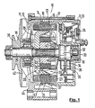
- alternator 10 is an alternator, as it is installed in motor vehicles today.
- the application of the subject invention is not limited to three-phase pot type generators as shown, but is generally applicable to alternators.
- This alternator or alternator 10 has a metal housing two end shields 12 and 13, between the open end portions 14 and 15, a stator 16 is clamped.
- a stator 16 is clamped to connect the two end shields 12 and 13 with the stand 16 serve as clamping elements 17 stud bolts, which are fixed in the two end shields 12 and 13.
- the end shields 12 and 13 each deploy a ball bearing 18 and 19 for rotatably receiving a claw pole runner 20.
- the stand is composed of sheets (lamellae), which consist of magnetizable iron and are pressed together to form a solid laminated core.
- the substantially annular stator 16 is provided in its stator bore 21 with grooves 22 for receiving AC windings 23.
- the AC windings 23 are in this three-phase alternator 10 to three electrical 120 ° spatially offset wave-shaped windings, which delivered a three-phase usable generator power to a fixed to the alternator 10, indicated rectifier 24 during operation of the alternator.
- the rectifier 24 converts the alternating current into direct current.
- the claw-pole rotor 20 is essentially composed of a rotor shaft 25 rotatably received in the ball bearings 18 and 19, two pole wheels 26 and 27 spaced apart from each other on this rotor shaft 25 with their claw poles 28 and 29, one between the two pole wheels 26 and 27 arranged, also pushed onto the rotor shaft 25 pole core 30 of magnetizable material, wound on the pole core 30 and from the two pole wheels 26 and 27 and the almost parallel to the rotor shaft 25 extending claw poles 28 and 29 included excitation winding 31 and beyond of two also on the rotor shaft 25 side by side with spaced slip rings 32 and 33, which are electrically connected to one end of the excitation winding 31.
- the plastic brush holder 36 is fixed to the bearing plate 13.
- the exciting winding 31 supplied excitation current is measured by a voltage regulator, not shown, usually attached to the alternator 10 such that the generator voltage over the entire speed range of the alternator or the respective vehicle engine, not shown remains approximately constant, regardless of load and speed.
- the claw-pole rotor 20 preferably has six claw poles 28 and 29 on each of its two pole wheels 26 and 27, which mesh with each other in a finger-like manner but with insulating spacing from one another.
- the two claw poles 28 and 29 have different polarity and cause a magnetic field.
- the air gap between the claw poles 28 and 29 and the stator bore 21 is denoted by 37.
- a drive pulley of the alternator 10 serving pulley 38 is disposed on the rotor shaft 25.
- the pulley 38 forms a component with a fan 42, which ensures the transport of cooling air through the alternator 10.
- the fan 42 may also be a separate component, which may be arranged both outside and inside the metallic housing 11.
- a fan 42 can also be arranged within the housing on both sides of the claw-pole rotor 20 (so-called compact generator).
- the drive-side bearing plate 12 is provided with a pivot arm 44.
- a second, for the accurate fixation of the alternator 10 appropriate fastener is in the FIG. 1 not shown.
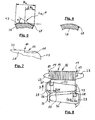
- FIG. 2a is the pole wheel 26 with its six evenly distributed on its circumference claw poles 28 shown.
- the pole wheel 26 and the claw poles 28 are made in the present example of a single piece of magnetizable material, but may also be composed of several individual parts.
- the pole wheel 27 and its claw pole 29 substantially corresponds to the pole wheel 26 with its claw poles 28.
- In the center of the pole wheel 26 is a central bore 45, in which the rotor shaft 25 is fixed.
- the fixing of the pole wheel on the rotor shaft is preferably effected by a knurling region 46 on the corresponding region of the rotor shaft 25 and additional caulking regions 27 between the edge of the center bore 45 of the pole wheel 26 and the rotor shaft 25.
- FIG. 2a On the left side of the pole wheel 26 is provided with an arrow and the name D, the intended direction of rotation in the generation of the generator current.
- a plate region 50 of the pole wheel 26 is shown. Starting from this plate region 50, a pole root 53 extends radially outward. Each pole root 53 of each claw pole 28 is separated from the adjacent pole root by a gap 56. Via the pole root 53, the free-standing part of the claw pole 28 is supported on the plate region 50.
- pole root 53 and plate area 50 the following definition applies:
- the plate portion 50 connects to the rotor shaft 25 and terminates radially outward where either the gap 56 or a pole root 53 begins.
- the beginning of a pole root 53 radially outward is determined by inscribing a circular arc 57 between two adjacent interstices 56 and their radially innermost extent or position, FIG. 2a , Since the innermost extent of each gap is additionally dependent on its axial position, a complex interface between pole root 53 and plate area 50 may result.
- An axial boundary between the pole root 53 and the cantilevered part of the claw pole 28 should here be defined by the fact that this boundary 59 is a radially outwardly theoretically elongated surface which extends from the surface 62 of the plate region 50 directed toward the exciter winding 31.
- the cylindrical surface 43 of the claw pole 28 defines an axis of rotation 65 (and vice versa), see also FIG. 2b ,
- FIG. 3 a plan view of a claw pole 28 and the adjacent plate area 50 is shown. Clearly visible here is the plate area 50, the pole root 53, the boundary 59 and the free-standing part of the claw pole 28.
- This claw pole 28 has two important edges, which can be determined more closely based on the direction of rotation D of the pole wheel 26.
- the uprising edge oriented in the direction of rotation D is referred to here as the edge 73.
- the other edge 70 since oriented against the direction of rotation D, referred to as the so-called running edge.
- the chamfer 68 is located on the side of the claw pole 28, which carries the leading edge 73.
- the edge 73 defines an edge direction in which the chamfer extends in one direction.
- the direction of rotation D defines a circumferential direction in which the chamfer 68 also extends.
- FIG. 4 shows an enlarged view of a portion of the area of the claw pole 28 and the pole root 53, which describes the vicinity of the chamfer 68.
- the chamfer 68 has a length 1, which is defined in the edge direction. Furthermore, the chamfer 68 has a Center section m, which extends in the same direction.
- the chamfer 68 has a center M which, based on the length 1, divides it centrally.
- the center section m is arranged symmetrically to the center M. This means that the remaining lengths on both sides of the center section m are equal.
- the center section m and the two lateral edge sections thus form the overall length 1 of the chamfer 68.
- the lines delimiting the chamfer 68 need not be rectilinear otherwise.
- the boundary line lying on the pole root 53 may assume a significantly different form.
- the transition plane 59 from the pole root 53 to the claw pole 28 is shown here. It is provided that the transition plane 59 intersects the middle section m in the region of the chamfer 68.
- the center section m should be 8/10 of the axial length 1 of the chamfer 68.
- FIG. 5 is a cross section through the claw pole 28, see also FIG. 4 ,
- the claw pole in the circumferential direction has a width B K.
- a center line L M is defined, which bisects the surface of a claw pole 28 at half the width B K.
- the center line L M can - depending on the shape of the claw pole 28 - be parallel to the axis of rotation 65, see also FIG. 3 .
- the midline L M is in FIG. 5 also recognizable as point P.
- point P can in a direction perpendicular to the axis of rotation 65 oriented plane (here leaf level of FIG. 5 ) a tangent T are inscribed, so that the tangent T and the chamfer 68 at point P include an inclination angle ⁇ which has a size between 15 ° and 25 °.
- a claw-pole rotor 20 is provided for an electric machine 10, in particular an alternator, with two pole wheels 26 and 27, which carry a plurality of claw poles 28 and 29, respectively, starting from a plate area 50.
- Each claw pole 28 and 29 each have a pole root 53.
- Claw poles 28 and 29 of the pole wheels 26 and 27 alternate at a circumference of the claw-pole rotor 20. Between the claw poles 28 and 29, intermediate spaces are arranged.
- Each claw pole 28 or 29 has a radially outwardly directed cylinder jacket-shaped surface 43, through which a rotation axis 65 is determined.
- a chamfer 68 extends on the one hand in a circumferential direction s U and on the other hand in an edge direction of a claw pole 28.
- the chamfer 68 has a center section m in the edge direction which has a transition plane delimiting the pole root 53 and the free-standing claw pole 28 59 cuts. It is provided that the center section m 8/10 of the axial length 1 of the chamfer 68.
- the chamfer also assigns according to the FIG. 5 given definition an inclination angle ⁇ between 15 ° and 25 °, which is included between the surface of the chamfer 68 and the tangent T at a point P.
- the point P shares in terms of its position or position.
- the center section m can according to a further embodiment of the invention also amount to only 1/3 of the axial length 1 of the chamfer 68.
- the chamfer 68 has in the edge direction a center M, which lies near the transition plane 59 from the pole root 53 to the cantilevered part of the claw pole 28 and 29, respectively.
- the chamfer 68 extends in the direction of rotation axis - starting from the transition plane 59 - with a length I a . It is envisaged that the chamfer 68 in the rotational axis direction in a first approximation with a length I a of up to 5 mm, in the second approximation with 2 mm on the cantilevered Klauenpol 28 extends.
- the chamfer 68 has a width b F which is between 4 mm and 6 mm.
- the chamfer 68 should have a length 1 between 4 mm and 6 mm.
- the chamfer 68 should be a plane which is oriented in an exemplary embodiment parallel to the rotation axis direction 65.
- the chamfer 68 may also be a plane that is oriented parallel to the edge direction 73.
- chamfer 68 is not a plane, but a deviating, here designated as free-form surface area, the last two mentioned features do not apply. All other aforementioned chamfer 68 may refer both to a flat design of the chamfer 68 and to an uneven design of the chamfer 68.
- chamfer 68 toward the free end of a claw pole 28 and 29 a step-shaped Transition 80 in the cylinder jacket-shaped surface 43 has.
- the chamfer 68 thus forms a notch 83 with the step 80.
- the chamfer 68 can also be produced with a chip-producing machining process.
- FIG. 8 1 shows a section of a portion of the generator 10.
- the stator 16 is once on the stator iron 86 and the AC winding 23.
- the AC winding 23 has near the end portion 14 openings 89.
- this opening 89 is limited on the one hand by the AC winding 23 and on the other hand by the end region of the stator iron 68.
- the stand 36 or, for example, also has 48 slots, there are usually thirty-six or forty-eight openings 89.
- FIG. 8 shows cylindrical surface 43 tilted in the viewing plane. It is based on FIG.
- an alternator 10 on the one hand has a ring-cylindrical stator iron 86 and a claw rotor 20 according to the invention, wherein the chamfer 68 protrudes under the stator iron 86 such that a portion of the chamfer 68 remains outside of the stator iron 86.
- the chamfer 68 should protrude at least 1 mm below the stator iron 86.
- the corresponding length specification is the dimension I F, st .
- each claw pole 28 and 29 has an edge 70 which is oriented against the direction of rotation D. Furthermore, each claw pole has an edge 73 which is oriented in the direction of rotation D and is referred to here as a leading edge.
- the chamfer 68 is in each case arranged on the side of each claw pole 28 or 29 which carries the edge 73 oriented in the direction of rotation D.
- the invention is not limited to pole wheels 26 and 27, each with six claw poles 28 and 29, but also applies to Polradaushebrened with seven or more particularly eight claw poles 28 and 29th
- the invention is not limited to Klauenpol routiner 20 having free spaces 56, but also applicable to such embodiments, which are filled or closed by means of a KlauenpolverBankes not shown here.
Landscapes
- Engineering & Computer Science (AREA)
- Power Engineering (AREA)
- Manufacturing & Machinery (AREA)
- Iron Core Of Rotating Electric Machines (AREA)
- Synchronous Machinery (AREA)
Applications Claiming Priority (2)
| Application Number | Priority Date | Filing Date | Title |
|---|---|---|---|
| DE102004001844A DE102004001844A1 (de) | 2004-01-02 | 2004-01-02 | Verfahren zur Herstellung eines Polrads sowie Klauenpolläufer mit Polrädern |
| PCT/EP2004/053731 WO2005067123A1 (de) | 2004-01-02 | 2004-12-30 | Klauenpolläufer für eine elektrische maschine |
Publications (2)
| Publication Number | Publication Date |
|---|---|
| EP1702397A1 EP1702397A1 (de) | 2006-09-20 |
| EP1702397B1 true EP1702397B1 (de) | 2010-09-08 |
Family
ID=34744703
Family Applications (1)
| Application Number | Title | Priority Date | Filing Date |
|---|---|---|---|
| EP04805056A Active EP1702397B1 (de) | 2004-01-02 | 2004-12-30 | Klauenpolläufer für eine elektrische maschine |
Country Status (6)
| Country | Link |
|---|---|
| US (1) | US7679259B2 (ko) |
| EP (1) | EP1702397B1 (ko) |
| KR (1) | KR101017855B1 (ko) |
| CN (1) | CN1926746B (ko) |
| DE (2) | DE102004001844A1 (ko) |
| WO (1) | WO2005067123A1 (ko) |
Families Citing this family (10)
| Publication number | Priority date | Publication date | Assignee | Title |
|---|---|---|---|---|
| DE102006007766B4 (de) * | 2006-02-20 | 2014-03-13 | Webasto Ag | Verfahren und Vorrichtung zum Steuern des Bewegungsablaufs eines Verdecksystems |
| US8629597B2 (en) * | 2010-03-03 | 2014-01-14 | Remy Technologies, Llc | Airflow passage arrangement for claw-pole electric machines |
| FR2969857B1 (fr) * | 2010-12-22 | 2013-12-20 | Francecol Technology | Perfectionnements aux moteurs homopolaires. |
| DE102010064377A1 (de) | 2010-12-30 | 2012-07-05 | Robert Bosch Gmbh | Elektrische Maschine |
| JP5920204B2 (ja) * | 2012-12-25 | 2016-05-18 | 株式会社デンソー | 車両用交流発電機の回転子 |
| KR101704119B1 (ko) | 2014-09-17 | 2017-02-07 | 현대자동차주식회사 | 클로 폴형 회전자 및 이를 적용한 모터 |
| FR3028359B1 (fr) * | 2014-11-12 | 2018-05-18 | Valeo Equipements Electriques Moteur | Rotor de machine electrique tournante |
| CN105681189B (zh) | 2016-01-21 | 2019-05-17 | 上海芃矽半导体技术有限公司 | 用于网格网络的数据转发方法及节点设备 |
| JP6305608B1 (ja) * | 2017-05-24 | 2018-04-04 | 三菱電機株式会社 | 車両用回転電機 |
| CN110113800A (zh) | 2019-05-05 | 2019-08-09 | 矽力杰半导体技术(杭州)有限公司 | 数据转发方法及存储装置 |
Family Cites Families (13)
| Publication number | Priority date | Publication date | Assignee | Title |
|---|---|---|---|---|
| FR2082430A5 (ko) * | 1970-03-16 | 1971-12-10 | Ducellier & Cie | |
| JPS5187705A (ja) | 1975-01-31 | 1976-07-31 | Hitachi Ltd | Sharyoyokoryuhatsudenki |
| DE3704156A1 (de) | 1987-02-11 | 1988-08-25 | Bosch Gmbh Robert | Wechselstromgenerator mit klauenpolrotor |
| JPH0648897B2 (ja) | 1989-12-28 | 1994-06-22 | 株式会社三ツ葉電機製作所 | 車両用交流発電機におけるロータコアの爪部形状 |
| JPH07222415A (ja) * | 1994-02-02 | 1995-08-18 | Mitsubishi Electric Corp | 車両用交流発電機 |
| US5747913A (en) * | 1995-05-12 | 1998-05-05 | General Motors Corporation | Rotor for hybrid generator having improved magnet retention |
| JP3265967B2 (ja) * | 1996-02-09 | 2002-03-18 | 株式会社デンソー | 交流発電機 |
| JP3929615B2 (ja) * | 1998-09-01 | 2007-06-13 | 三菱電機株式会社 | 車両用交流発電機 |
| FR2786625B1 (fr) * | 1998-11-30 | 2001-02-16 | Valeo Equip Electr Moteur | Alternateur de vehicule automobile a aimants interpolaires |
| JP3696062B2 (ja) | 2000-08-10 | 2005-09-14 | 三菱電機株式会社 | 車両用交流発電機 |
| JP3820916B2 (ja) * | 2001-05-29 | 2006-09-13 | 三菱電機株式会社 | 車両用交流発電機 |
| JP3789361B2 (ja) * | 2002-01-18 | 2006-06-21 | 株式会社デンソー | 交流発電機 |
| JP2003219617A (ja) | 2002-01-21 | 2003-07-31 | Mitsubishi Electric Corp | 交流発電機 |
-
2004
- 2004-01-02 DE DE102004001844A patent/DE102004001844A1/de not_active Withdrawn
- 2004-12-30 WO PCT/EP2004/053731 patent/WO2005067123A1/de not_active Application Discontinuation
- 2004-12-30 US US10/585,047 patent/US7679259B2/en active Active
- 2004-12-30 EP EP04805056A patent/EP1702397B1/de active Active
- 2004-12-30 DE DE502004011647T patent/DE502004011647D1/de active Active
- 2004-12-30 KR KR1020067013245A patent/KR101017855B1/ko active IP Right Grant
- 2004-12-30 CN CN2004800397260A patent/CN1926746B/zh active Active
Also Published As
| Publication number | Publication date |
|---|---|
| DE502004011647D1 (de) | 2010-10-21 |
| CN1926746A (zh) | 2007-03-07 |
| DE102004001844A1 (de) | 2005-08-11 |
| US7679259B2 (en) | 2010-03-16 |
| WO2005067123A1 (de) | 2005-07-21 |
| CN1926746B (zh) | 2011-01-26 |
| US20080024033A1 (en) | 2008-01-31 |
| EP1702397A1 (de) | 2006-09-20 |
| KR20060111655A (ko) | 2006-10-27 |
| KR101017855B1 (ko) | 2011-03-04 |
Similar Documents
| Publication | Publication Date | Title |
|---|---|---|
| EP0346346B1 (de) | Wechselstromgenerator mit klauenpolrotor | |
| EP1145407A1 (de) | Klauenpolmaschine | |
| DE1291012B (de) | Elektrischer Drehstromgenerator, insbesondere fuer Kraftfahrzeuge | |
| DE102010041015A1 (de) | Maschinenkomponente für eine elektrische Maschine | |
| DE3410760C2 (ko) | ||
| EP1702397B1 (de) | Klauenpolläufer für eine elektrische maschine | |
| DE60201937T2 (de) | Elektrische Maschine mit äusserem Läufer | |
| DE10153578A1 (de) | Wechselstromgenerator für Fahrzeuge mit Permanentmagneten im Rotor und Verfahren zur Herstellung desselben | |
| DE10229333A1 (de) | Elektrische Maschine, insbesondere bürstenlose Maschine mit permanentmagnetisch erregtem Läufer | |
| DE2808347C2 (ko) | ||
| DE102016008686A1 (de) | Kernkörper für Statoren und/oder Rotoren von elektrischen Maschinen, Stator/Rotor mit einem solchen Kernkörper sowie elektrische Maschine mit einem solchen Kernkörper | |
| WO2019171218A1 (de) | Rotoreinheit und elektromotor | |
| EP1155490B1 (de) | Klauenpol-generator mit schwingungsdämpfung | |
| EP1976102A2 (de) | Elektrische Homopolarmaschine | |
| DE10335688A1 (de) | Luftspule innerhalb von rotierenden elektrischen Maschinen und deren Herstellungsverfahren | |
| DE102016223084A1 (de) | Lamelle für einen Rotor oder Stator einer elektrischen Maschine sowie Rotor oder Stator mit der Lamelle | |
| DE60214294T2 (de) | Wechselstromgenerator | |
| DE102021104785A1 (de) | Läufer für eine Synchronmaschine | |
| DE102019005465A1 (de) | Elektrische rotationsmaschine, ausgestattet mit einem rotor verringerter masse | |
| WO2019171219A1 (de) | Rotoreinheit und elektromotor | |
| EP2871752B1 (de) | Läufer einer rotatorischen permanenterregten Synchronmaschine | |
| DE10119830A1 (de) | Verfahren zur Herstellung einer rotierenden elektrischen Maschine sowie rotierende elektrische Maschine | |
| DE3722153A1 (de) | Elektrodynamische synchronmaschine | |
| DE112016005481T5 (de) | Klauenrotor einer elektrischen Rotationsmaschine mit Klauen, die eine bogenförmige Fase haben | |
| DE10056875A1 (de) | Rotor für eine elektrische Maschine |
Legal Events
| Date | Code | Title | Description |
|---|---|---|---|
| PUAI | Public reference made under article 153(3) epc to a published international application that has entered the european phase |
Free format text: ORIGINAL CODE: 0009012 |
|
| 17P | Request for examination filed |
Effective date: 20060802 |
|
| AK | Designated contracting states |
Kind code of ref document: A1 Designated state(s): DE FR IT |
|
| DAX | Request for extension of the european patent (deleted) | ||
| RBV | Designated contracting states (corrected) |
Designated state(s): DE FR IT |
|
| 17Q | First examination report despatched |
Effective date: 20080421 |
|
| GRAP | Despatch of communication of intention to grant a patent |
Free format text: ORIGINAL CODE: EPIDOSNIGR1 |
|
| GRAS | Grant fee paid |
Free format text: ORIGINAL CODE: EPIDOSNIGR3 |
|
| GRAA | (expected) grant |
Free format text: ORIGINAL CODE: 0009210 |
|
| AK | Designated contracting states |
Kind code of ref document: B1 Designated state(s): DE FR IT |
|
| REF | Corresponds to: |
Ref document number: 502004011647 Country of ref document: DE Date of ref document: 20101021 Kind code of ref document: P |
|
| PLBE | No opposition filed within time limit |
Free format text: ORIGINAL CODE: 0009261 |
|
| STAA | Information on the status of an ep patent application or granted ep patent |
Free format text: STATUS: NO OPPOSITION FILED WITHIN TIME LIMIT |
|
| 26N | No opposition filed |
Effective date: 20110609 |
|
| REG | Reference to a national code |
Ref country code: DE Ref legal event code: R097 Ref document number: 502004011647 Country of ref document: DE Effective date: 20110609 |
|
| REG | Reference to a national code |
Ref country code: FR Ref legal event code: PLFP Year of fee payment: 12 |
|
| REG | Reference to a national code |
Ref country code: FR Ref legal event code: PLFP Year of fee payment: 13 |
|
| REG | Reference to a national code |
Ref country code: DE Ref legal event code: R081 Ref document number: 502004011647 Country of ref document: DE Owner name: SEG AUTOMOTIVE GERMANY GMBH, DE Free format text: FORMER OWNER: ROBERT BOSCH GMBH, 70469 STUTTGART, DE |
|
| REG | Reference to a national code |
Ref country code: FR Ref legal event code: PLFP Year of fee payment: 14 |
|
| REG | Reference to a national code |
Ref country code: FR Ref legal event code: TP Owner name: SEG AUTOMOTIVE GERMANY GMBH, DE Effective date: 20180315 |
|
| REG | Reference to a national code |
Ref country code: DE Ref legal event code: R082 Ref document number: 502004011647 Country of ref document: DE Representative=s name: DEHNSGERMANY PARTNERSCHAFT VON PATENTANWAELTEN, DE Ref country code: DE Ref legal event code: R082 Ref document number: 502004011647 Country of ref document: DE Representative=s name: DEHNS GERMANY PARTNERSCHAFT MBB, DE |
|
| PGFP | Annual fee paid to national office [announced via postgrant information from national office to epo] |
Ref country code: IT Payment date: 20231228 Year of fee payment: 20 Ref country code: FR Payment date: 20231219 Year of fee payment: 20 Ref country code: DE Payment date: 20231220 Year of fee payment: 20 |