EP1701121A2 - Wärmebehandlungsofen - Google Patents
Wärmebehandlungsofen Download PDFInfo
- Publication number
- EP1701121A2 EP1701121A2 EP20060110907 EP06110907A EP1701121A2 EP 1701121 A2 EP1701121 A2 EP 1701121A2 EP 20060110907 EP20060110907 EP 20060110907 EP 06110907 A EP06110907 A EP 06110907A EP 1701121 A2 EP1701121 A2 EP 1701121A2
- Authority
- EP
- European Patent Office
- Prior art keywords
- subject
- thermally treated
- fan
- thermal
- thermal treatment
- Prior art date
- Legal status (The legal status is an assumption and is not a legal conclusion. Google has not performed a legal analysis and makes no representation as to the accuracy of the status listed.)
- Withdrawn
Links
- 238000007669 thermal treatment Methods 0.000 title claims abstract description 32
- 238000003756 stirring Methods 0.000 claims abstract description 10
- 239000012809 cooling fluid Substances 0.000 claims description 12
- 230000000171 quenching effect Effects 0.000 abstract description 14
- 238000010791 quenching Methods 0.000 abstract description 13
- 239000000112 cooling gas Substances 0.000 abstract description 5
- 238000001816 cooling Methods 0.000 description 24
- 238000010438 heat treatment Methods 0.000 description 13
- 230000005611 electricity Effects 0.000 description 11
- 239000007789 gas Substances 0.000 description 7
- 239000012530 fluid Substances 0.000 description 6
- 238000009413 insulation Methods 0.000 description 5
- 239000011261 inert gas Substances 0.000 description 4
- NJPPVKZQTLUDBO-UHFFFAOYSA-N novaluron Chemical compound C1=C(Cl)C(OC(F)(F)C(OC(F)(F)F)F)=CC=C1NC(=O)NC(=O)C1=C(F)C=CC=C1F NJPPVKZQTLUDBO-UHFFFAOYSA-N 0.000 description 3
- 238000005192 partition Methods 0.000 description 3
- 238000012546 transfer Methods 0.000 description 3
- OKTJSMMVPCPJKN-UHFFFAOYSA-N Carbon Chemical compound [C] OKTJSMMVPCPJKN-UHFFFAOYSA-N 0.000 description 2
- 229910002804 graphite Inorganic materials 0.000 description 2
- 239000010439 graphite Substances 0.000 description 2
- 239000000463 material Substances 0.000 description 2
- 238000006243 chemical reaction Methods 0.000 description 1
- 238000002485 combustion reaction Methods 0.000 description 1
- 238000004891 communication Methods 0.000 description 1
- 239000000470 constituent Substances 0.000 description 1
- 238000013461 design Methods 0.000 description 1
- 239000006185 dispersion Substances 0.000 description 1
- 230000000694 effects Effects 0.000 description 1
- 239000000446 fuel Substances 0.000 description 1
- -1 i.e. Substances 0.000 description 1
- 238000007689 inspection Methods 0.000 description 1
- 238000000034 method Methods 0.000 description 1
- 238000012986 modification Methods 0.000 description 1
- 230000004048 modification Effects 0.000 description 1
- 238000012545 processing Methods 0.000 description 1
- 239000003507 refrigerant Substances 0.000 description 1
- 230000009291 secondary effect Effects 0.000 description 1
- 238000002791 soaking Methods 0.000 description 1
- XLYOFNOQVPJJNP-UHFFFAOYSA-N water Substances O XLYOFNOQVPJJNP-UHFFFAOYSA-N 0.000 description 1
- 238000004804 winding Methods 0.000 description 1
Images


Classifications
-
- F—MECHANICAL ENGINEERING; LIGHTING; HEATING; WEAPONS; BLASTING
- F27—FURNACES; KILNS; OVENS; RETORTS
- F27B—FURNACES, KILNS, OVENS OR RETORTS IN GENERAL; OPEN SINTERING OR LIKE APPARATUS
- F27B5/00—Muffle furnaces; Retort furnaces; Other furnaces in which the charge is held completely isolated
- F27B5/06—Details, accessories or equipment specially adapted for furnaces of these types
- F27B5/16—Arrangements of air or gas supply devices
-
- F—MECHANICAL ENGINEERING; LIGHTING; HEATING; WEAPONS; BLASTING
- F27—FURNACES; KILNS; OVENS; RETORTS
- F27B—FURNACES, KILNS, OVENS OR RETORTS IN GENERAL; OPEN SINTERING OR LIKE APPARATUS
- F27B5/00—Muffle furnaces; Retort furnaces; Other furnaces in which the charge is held completely isolated
- F27B5/04—Muffle furnaces; Retort furnaces; Other furnaces in which the charge is held completely isolated adapted for treating the charge in vacuum or special atmosphere
-
- F—MECHANICAL ENGINEERING; LIGHTING; HEATING; WEAPONS; BLASTING
- F27—FURNACES; KILNS; OVENS; RETORTS
- F27B—FURNACES, KILNS, OVENS OR RETORTS IN GENERAL; OPEN SINTERING OR LIKE APPARATUS
- F27B5/00—Muffle furnaces; Retort furnaces; Other furnaces in which the charge is held completely isolated
- F27B5/06—Details, accessories or equipment specially adapted for furnaces of these types
-
- F—MECHANICAL ENGINEERING; LIGHTING; HEATING; WEAPONS; BLASTING
- F27—FURNACES; KILNS; OVENS; RETORTS
- F27D—DETAILS OR ACCESSORIES OF FURNACES, KILNS, OVENS OR RETORTS, IN SO FAR AS THEY ARE OF KINDS OCCURRING IN MORE THAN ONE KIND OF FURNACE
- F27D7/00—Forming, maintaining or circulating atmospheres in heating chambers
- F27D7/04—Circulating atmospheres by mechanical means
-
- F—MECHANICAL ENGINEERING; LIGHTING; HEATING; WEAPONS; BLASTING
- F27—FURNACES; KILNS; OVENS; RETORTS
- F27D—DETAILS OR ACCESSORIES OF FURNACES, KILNS, OVENS OR RETORTS, IN SO FAR AS THEY ARE OF KINDS OCCURRING IN MORE THAN ONE KIND OF FURNACE
- F27D9/00—Cooling of furnaces or of charges therein
-
- F—MECHANICAL ENGINEERING; LIGHTING; HEATING; WEAPONS; BLASTING
- F27—FURNACES; KILNS; OVENS; RETORTS
- F27D—DETAILS OR ACCESSORIES OF FURNACES, KILNS, OVENS OR RETORTS, IN SO FAR AS THEY ARE OF KINDS OCCURRING IN MORE THAN ONE KIND OF FURNACE
- F27D7/00—Forming, maintaining or circulating atmospheres in heating chambers
- F27D7/04—Circulating atmospheres by mechanical means
- F27D2007/045—Fans
-
- F—MECHANICAL ENGINEERING; LIGHTING; HEATING; WEAPONS; BLASTING
- F27—FURNACES; KILNS; OVENS; RETORTS
- F27D—DETAILS OR ACCESSORIES OF FURNACES, KILNS, OVENS OR RETORTS, IN SO FAR AS THEY ARE OF KINDS OCCURRING IN MORE THAN ONE KIND OF FURNACE
- F27D9/00—Cooling of furnaces or of charges therein
- F27D2009/007—Cooling of charges therein
- F27D2009/0072—Cooling of charges therein the cooling medium being a gas
- F27D2009/0075—Cooling of charges therein the cooling medium being a gas in direct contact with the charge
Definitions
- the present invention relates to a thermal treatment furnace for subjecting a subject to be thermally treated to quenching and the like.
- a vacuum thermal treatment furnace As an apparatus for subjecting a subject to be thermally treated such as a mold to quenching, a vacuum thermal treatment furnace is known (see the following patent document).
- the typical vacuum thermal treatment furnace after the subject to be thermally treated is heated for a predetermined time in the furnace being formed a vacuum, the subject to be thermally treated is put into an oil tank, or the low temperature cooling gas is stirred using a fan during charging therein, thereby rapidly cooling the subject to be thermally treated.
- To cool the subject to be thermally treated using gas has many merits that the subject to be thermally treated is not contaminated by oil, and the cooling speed is lowered so that thermal deformation of the subject to be thermally treated can be avoided.
- Patent Document 1 Japanese Patent Application Laid-Open No.H10-183236
- the cooling step is only a portion of the entire steps. Usually, it takes one to two hours for increasing the temperatures in the furnace and of the subject, it takes several hours for a soaking step, and it takes one to two hours for a cooling step of the subject. That is, the time for driving the fan using the electric motor is only about one to two hours, time during which the electric motor and the fan are stopped is longer.
- the electric motor is operated only for several hours a day, from the standpoint of an electric company which generates and supplies electricity, it is necessary to always keep holding electricity-generating ability and electricity-supplying ability so that no problem is generated whenever the electric motor is operated.
- the actual electric bill is a sum of a charge on an as-used basis corresponding to consumed electricity and a basic charge corresponding to the equipment electricity.
- An electric motor of high output increases the equipment electricity value and thus, time during which the electric motor is not operated a day is long irrespective of high basic charge. Users of thermal treatment furnaces bear illogical costs.
- the present invention contrived with an innovative idea based on an attempt first focusing on the above noted problems, provides a thermal treatment furnace having a thermal engine, for subjecting a subject to be thermally treated to a quenching treatment, wherein the thermal engine drives a fan for a period during which the subject to be thermally treated is cooled.
- the thermal treatment furnace of the present invention is suitable for being operated in various countries where electricity circumstances are unstable as compared with Japan.
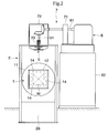
- a thermal treatment furnace of the embodiment is a vacuum thermal treatment furnace in which a subject to be thermally treated W in its vacuum state is heated and then, the subject to be thermally treated W is put into an oil tank 26, or cooling fluid is stirred by a fan 5 while the cooling fluid being charged therein, thereby rapidly cooling the subject to be thermally treated W.
- the thermal treatment furnace is of a double structure including a heating chamber 1 for heating the subject to be thermally treated W, and a cooling chamber 2 for cooling the subject to be thermally treated W heated in the heating chamber 1.
- the thermal treatment furnace is provided with a thermal insulation body 12, a heater 14, a vacuum exhaust system 3 and the like, as a part of the heating chamber 1, and provided with an oil tank 26, a fluid introducing system 4, the fan 5 and the like; as a part of the cooling chamber 2.
- the substantially box-like thermal insulation body 12 is disposed in a furnace barrel 11 which is an outer shell of the heating chamber 1, and disposed inside is the heater 14, thereby constituting a thermal treatment space for heating the subject to be thermally treated W.
- a thermal insulating lid 13 being openable and closable is provided on the side of the cooling chamber 2 of the thermal insulation body 12. The thermal insulating lid 13 can be opened and closed.
- the thermal insulation body 12 and the thermal insulating lid 13 are made of graphite felt for example.
- the vacuum exhaust system 3 is formed by serially connecting a dispersion pump (not shown), a mechanical booster pump (not shown) and a hydraulic rotation vacuum pump (not shown) and so on, and the vacuum exhaust system 3 is connected to the furnace barrel 11 through a valve such that they can be connected and disconnected to and from each other.
- the heater 14 is a graphite heater or the like capable of heating the subject to be thermally treated W to a desired temperature.
- the heater 14 is disposed at a location surrounding the subject to be thermally treated W in the thermal treatment space.
- the furnace barrel 11 is in communication with a housing 21 which is an outer shell of the cooling chamber 2.
- the furnace barrel 11 and the housing 21 are divided by a partition door 27 which integrally operated with the thermal insulating lid 13.
- the housing 21 is expanded in the vertical direction.
- a gas quenching space is formed by providing a fluid introducing system 4 in which cooling fluid (e.g., inert gas such as N2) is charged, the fan 5 for stirring and circulating the charged cooling fluid, and a heat exchanger 22 for cooling fluid which circulates in the housing 21.
- the fluid introducing system 4 sends inert gas for cooling the subject to be thermally treated W subjected to the thermal treatment from a gas cylinder (not shown) into the housing 21.
- a valve is provided in an intermediate portion of the fluid introducing system 4 of course.
- the fan 5 is disposed on an upper end of the housing 21, and a drive shaft 51 of the fan5 penetrates the housing 21 and projects upward.
- a vacuum seal 23 is provided on a portion of the fan 5 where the drive shaft 51 penetrates the housing 21.
- a passage e.g., water cooling opening in the shaft (not shown)
- refrigerant flows may be provided in the drive shaft 51 as means for cooling the drive shaft 51 of the fan 5.
- An inlet/outlet 24 through which the subject to be thermally treated W is brought into and out from the housing 21 is provided at a necessary location of the housing 21.
- the inlet/outlet 24 is tightly closed by an opening and closing door 25.
- a lower region of the housing 21 is formed with the oil tank 26 for accumulating quenching oil as the oil quenching space, but this oil tank 26 is not absolutely necessary.
- a thermal engine 6 which outputs driving force for driving the fan 5 is provided.
- a transmitting mechanism 7 is interposed between an output shaft 61 of the thermal engine 6 and the drive shaft 51 of the fan 5 to connect the output shaft 61 and the drive shaft 51 with each other.
- the thermal engine 6 burns fuel to take out mechanical energy to rotate the output shaft 61 (especially internal combustion engine), but its concrete structure is not limited. It is possible to employ various thermal engines such as diesel engine, gasoline engine and gas turbine engine as the thermal engine 6 in accordance with design specification and other circumstances. Preferably, a known revolving speed control mechanism (not shown) used for an automobile and a ship is applied to control the revolving speed of the output shaft 61.
- the thermal engine 6 is supported by a pedestal 62 which is separated from the furnace barrel 11 and the housing 21.
- the transmitting mechanism 7 transmits rotation driving force which is outputted from the thermal engine 6 to the drive shaft 51 of the fan 5.
- the transmitting mechanism 7 comprises a clutch and bevel gears.
- a clutch box 71 accommodating the clutch is disposed on a pedestal 62
- a gear box 72 accommodating the bevel gears is disposed on the housing 21.
- the structure of the transmitting mechanism 7 is not limited to the above-described structure.
- the clutch and the bevel gear are not absolutely necessary. Gears other than the bevel gears may be employed of course. It is also possible to use winding transmitting means such as a belt and a chain.
- the reason why the thermal engine 6 is supported by the pedestal 62 and the transmitting mechanism 7 is interposed between the thermal engine 6 and the fan 5 is that when the thermal engine 6 is operated, its vibration can be prevented from being transmitted to the housing 21 and the furnace barrel 11.
- the subject to be thermally treated W sent from the inlet/outlet 24 is transferred into the thermal treatment space in the heating chamber 1 by a transfer mechanism (not shown), the thermal insulating lid 13 of the thermal insulation body 12 and the partition door 27 are closed, and the subject to be thermally treated W is heated. After the heating operation is completed, the thermal insulating lid 13 and the partition door 27 are opened, and the subject to be thermally treated W is transferred into a gas quenching space in the housing 21 by the transfer mechanism. Then, when the thermal engine 6 is started, the fan 5 is rotated.
- cooling fluid i.e., inert gas
- the inner chamber i.e., into the cooling chamber 2
- the fan 5 stirs the inert gas, and the subject to be thermally treated W is rapidly cooled.
- the internal pressure in the thermal treatment furnace is reduced to the atmospheric pressure, and the subject to be thermally treated W is transferred to a portion near the inlet/outlet 24 by the transfer mechanism.
- the thermal treatment furnace comprises the heating chamber 1 for heating the subject to be thermally treated W, the cooling chamber 2 into which the subject to be thermally treated W heated in the heating chamber 1 is transferred, the fan 5 for stirring fluid charged into the cooling chamber 2 for cooling the subject'to be thermally treated W, the thermal engine 6 for outputting the driving force which drives the fan 5 for a period during which the subject to be thermally treated W in the cooling chamber 2, is cooled using the fan 5 and the transmitting mechanism 7 for transmitting the driving force which is outputted from the thermal engine 6 to the drive shaft 51 of the fan 5. Therefore, it becomes unnecessary to provide massive power receiving equipment and power distributing equipment inside and outside of a factory. This also reduces illogical social costs for providing infrastructure whose non-operating time is longer than operating time. This is preferable for operation in various countries where the electricity circumstances are not stable as compared with Japan.
- the present invention is not limited to the above-described embodiment.
- a single chamber thermal treatment furnace in which the heating chamber 1 and the cooling chamber 2 are not separated from each other as shown in Fig. 3 may be employed.
- the drive shaft 51 of the fan 5 and the output shaft 61 of the thermal engine 6 are directed in substantially a horizontal direction, and they are substantially in parallel to each other.
- spur gears, helical gears or herringbone gears as an element of the transmitting mechanism 7 which connects the drive shaft 51 of the fan 5 and the output shaft 61 of the thermal engine 6 to each other.
- the drive shaft 51 of the fan 5 and the output shaft 61 of the thermal engine 6 are substantially in parallel to each other, they can directly be connected to each other without interposing the transmitting mechanism 7.
- the present invention provides a thermal treatment furnace suitable for quenching a large subject to be thermally treated, which is provided with a thermal engine 6, and a fan 5 is driven by the thermal engine 6 to stir high pressure cooling gas for a period during which the subject to be thermally treated W is cooled.
Landscapes
- Engineering & Computer Science (AREA)
- Mechanical Engineering (AREA)
- General Engineering & Computer Science (AREA)
- Furnace Details (AREA)
- Heat Treatments In General, Especially Conveying And Cooling (AREA)
- Waste-Gas Treatment And Other Accessory Devices For Furnaces (AREA)
- Muffle Furnaces And Rotary Kilns (AREA)
Applications Claiming Priority (1)
| Application Number | Priority Date | Filing Date | Title |
|---|---|---|---|
| JP2005068136 | 2005-03-10 |
Publications (2)
| Publication Number | Publication Date |
|---|---|
| EP1701121A2 true EP1701121A2 (de) | 2006-09-13 |
| EP1701121A3 EP1701121A3 (de) | 2007-07-25 |
Family
ID=36588914
Family Applications (1)
| Application Number | Title | Priority Date | Filing Date |
|---|---|---|---|
| EP06110907A Withdrawn EP1701121A3 (de) | 2005-03-10 | 2006-03-09 | Wärmebehandlungsofen |
Country Status (2)
| Country | Link |
|---|---|
| EP (1) | EP1701121A3 (de) |
| CN (1) | CN1831159A (de) |
Cited By (1)
| Publication number | Priority date | Publication date | Assignee | Title |
|---|---|---|---|---|
| CN109824368A (zh) * | 2018-12-14 | 2019-05-31 | 安泰天龙钨钼科技有限公司 | 一种低能耗热压生产氮化硼基陶瓷的方法和装置 |
Citations (1)
| Publication number | Priority date | Publication date | Assignee | Title |
|---|---|---|---|---|
| JPH10183236A (ja) | 1996-12-25 | 1998-07-14 | Shimazu Mekutemu Kk | 真空熱処理炉 |
Family Cites Families (1)
| Publication number | Priority date | Publication date | Assignee | Title |
|---|---|---|---|---|
| GB1274974A (en) * | 1970-04-01 | 1972-05-17 | Wild Barfield Ltd | Improvements in heat treatment furnaces |
-
2006
- 2006-03-09 EP EP06110907A patent/EP1701121A3/de not_active Withdrawn
- 2006-03-10 CN CNA2006100547644A patent/CN1831159A/zh active Pending
Patent Citations (1)
| Publication number | Priority date | Publication date | Assignee | Title |
|---|---|---|---|---|
| JPH10183236A (ja) | 1996-12-25 | 1998-07-14 | Shimazu Mekutemu Kk | 真空熱処理炉 |
Cited By (1)
| Publication number | Priority date | Publication date | Assignee | Title |
|---|---|---|---|---|
| CN109824368A (zh) * | 2018-12-14 | 2019-05-31 | 安泰天龙钨钼科技有限公司 | 一种低能耗热压生产氮化硼基陶瓷的方法和装置 |
Also Published As
| Publication number | Publication date |
|---|---|
| EP1701121A3 (de) | 2007-07-25 |
| CN1831159A (zh) | 2006-09-13 |
Similar Documents
| Publication | Publication Date | Title |
|---|---|---|
| CN110273758B (zh) | 微型燃气轮机发电机组 | |
| US8895172B2 (en) | Apparatus and method for controlling the temperature of a battery in a hybrid electric vehicle | |
| CN101660445A (zh) | 用于发电系统的顶装式消音器 | |
| KR101786670B1 (ko) | 차량용 냉각 시스템 | |
| US6931850B2 (en) | Exhaust gas driven generation of electric power and altitude compensation in vehicles including hybrid electric vehicles | |
| JP5583212B2 (ja) | ハイブリッド車両におけるエンジンオイル及びミッションオイルの加熱のための方法及び装置 | |
| US20060124275A1 (en) | Power supply system for a motor vehicle | |
| JP6595115B2 (ja) | 車両のためのドライブトレイン | |
| US20070137909A1 (en) | Hybrid drive unit having a low-temperature circuit | |
| CN103003544B (zh) | 混合动力车辆牵引系统的冷却设备及该设备的调节方法 | |
| KR20150130561A (ko) | 선박용 대형 디젤 엔진의 배기가스 에너지를 이용하는 선박 추진 시스템 | |
| JP2019055649A (ja) | バッテリー温度制御システム | |
| US20190291590A1 (en) | Mobile electricity-generator system on vehicles | |
| RU2247850C2 (ru) | Компактный электроэнергетический агрегат и метод вырабатывания энергии | |
| US6178733B1 (en) | External blower motor and starting motor for a combustion turbine system | |
| EP1701121A2 (de) | Wärmebehandlungsofen | |
| JP3125138U (ja) | 熱処理炉 | |
| EP1939436A1 (de) | Kraft-wärme-kopplungssystem | |
| JP4916545B2 (ja) | 熱処理装置 | |
| US20180058461A1 (en) | System for producing energy or torque | |
| JP2009068367A (ja) | 発電装置 | |
| Anatychuk et al. | On the possibility of using thermoelectric generators for high-power transport starting pre-heaters | |
| HK1092186A (en) | Thermal treatment | |
| KR20090059816A (ko) | 하이브리드 차량 모터용 냉각 장치 | |
| CN212563451U (zh) | 一种多功能工效机组 |
Legal Events
| Date | Code | Title | Description |
|---|---|---|---|
| PUAI | Public reference made under article 153(3) epc to a published international application that has entered the european phase |
Free format text: ORIGINAL CODE: 0009012 |
|
| 17P | Request for examination filed |
Effective date: 20060309 |
|
| AK | Designated contracting states |
Kind code of ref document: A2 Designated state(s): AT BE BG CH CY CZ DE DK EE ES FI FR GB GR HU IE IS IT LI LT LU LV MC NL PL PT RO SE SI SK TR |
|
| AX | Request for extension of the european patent |
Extension state: AL BA HR MK YU |
|
| PUAL | Search report despatched |
Free format text: ORIGINAL CODE: 0009013 |
|
| AK | Designated contracting states |
Kind code of ref document: A3 Designated state(s): AT BE BG CH CY CZ DE DK EE ES FI FR GB GR HU IE IS IT LI LT LU LV MC NL PL PT RO SE SI SK TR |
|
| AX | Request for extension of the european patent |
Extension state: AL BA HR MK YU |
|
| RIC1 | Information provided on ipc code assigned before grant |
Ipc: C21D 9/00 20060101ALI20070619BHEP Ipc: F27D 7/04 20060101ALI20070619BHEP Ipc: F27D 9/00 20060101ALI20070619BHEP Ipc: F27B 5/04 20060101ALI20070619BHEP Ipc: F27B 5/06 20060101AFI20060626BHEP |
|
| AKX | Designation fees paid |
Designated state(s): AT BE BG CH CY CZ DE DK EE ES FI FR GB GR HU IE IS IT LI LT LU LV MC NL PL PT RO SE SI SK TR |
|
| 17Q | First examination report despatched |
Effective date: 20090804 |
|
| GRAP | Despatch of communication of intention to grant a patent |
Free format text: ORIGINAL CODE: EPIDOSNIGR1 |
|
| INTG | Intention to grant announced |
Effective date: 20150423 |
|
| STAA | Information on the status of an ep patent application or granted ep patent |
Free format text: STATUS: THE APPLICATION IS DEEMED TO BE WITHDRAWN |
|
| 18D | Application deemed to be withdrawn |
Effective date: 20150904 |