EP1701121A2 - Thermal treatment furnace - Google Patents
Thermal treatment furnace Download PDFInfo
- Publication number
- EP1701121A2 EP1701121A2 EP20060110907 EP06110907A EP1701121A2 EP 1701121 A2 EP1701121 A2 EP 1701121A2 EP 20060110907 EP20060110907 EP 20060110907 EP 06110907 A EP06110907 A EP 06110907A EP 1701121 A2 EP1701121 A2 EP 1701121A2
- Authority
- EP
- European Patent Office
- Prior art keywords
- subject
- thermally treated
- fan
- thermal
- thermal treatment
- Prior art date
- Legal status (The legal status is an assumption and is not a legal conclusion. Google has not performed a legal analysis and makes no representation as to the accuracy of the status listed.)
- Withdrawn
Links
Images


Classifications
-
- F—MECHANICAL ENGINEERING; LIGHTING; HEATING; WEAPONS; BLASTING
- F27—FURNACES; KILNS; OVENS; RETORTS
- F27B—FURNACES, KILNS, OVENS, OR RETORTS IN GENERAL; OPEN SINTERING OR LIKE APPARATUS
- F27B5/00—Muffle furnaces; Retort furnaces; Other furnaces in which the charge is held completely isolated
- F27B5/06—Details, accessories, or equipment peculiar to furnaces of these types
- F27B5/16—Arrangements of air or gas supply devices
-
- F—MECHANICAL ENGINEERING; LIGHTING; HEATING; WEAPONS; BLASTING
- F27—FURNACES; KILNS; OVENS; RETORTS
- F27B—FURNACES, KILNS, OVENS, OR RETORTS IN GENERAL; OPEN SINTERING OR LIKE APPARATUS
- F27B5/00—Muffle furnaces; Retort furnaces; Other furnaces in which the charge is held completely isolated
- F27B5/04—Muffle furnaces; Retort furnaces; Other furnaces in which the charge is held completely isolated adapted for treating the charge in vacuum or special atmosphere
-
- F—MECHANICAL ENGINEERING; LIGHTING; HEATING; WEAPONS; BLASTING
- F27—FURNACES; KILNS; OVENS; RETORTS
- F27B—FURNACES, KILNS, OVENS, OR RETORTS IN GENERAL; OPEN SINTERING OR LIKE APPARATUS
- F27B5/00—Muffle furnaces; Retort furnaces; Other furnaces in which the charge is held completely isolated
- F27B5/06—Details, accessories, or equipment peculiar to furnaces of these types
-
- F—MECHANICAL ENGINEERING; LIGHTING; HEATING; WEAPONS; BLASTING
- F27—FURNACES; KILNS; OVENS; RETORTS
- F27D—DETAILS OR ACCESSORIES OF FURNACES, KILNS, OVENS, OR RETORTS, IN SO FAR AS THEY ARE OF KINDS OCCURRING IN MORE THAN ONE KIND OF FURNACE
- F27D7/00—Forming, maintaining, or circulating atmospheres in heating chambers
- F27D7/04—Circulating atmospheres by mechanical means
-
- F—MECHANICAL ENGINEERING; LIGHTING; HEATING; WEAPONS; BLASTING
- F27—FURNACES; KILNS; OVENS; RETORTS
- F27D—DETAILS OR ACCESSORIES OF FURNACES, KILNS, OVENS, OR RETORTS, IN SO FAR AS THEY ARE OF KINDS OCCURRING IN MORE THAN ONE KIND OF FURNACE
- F27D9/00—Cooling of furnaces or of charges therein
-
- F—MECHANICAL ENGINEERING; LIGHTING; HEATING; WEAPONS; BLASTING
- F27—FURNACES; KILNS; OVENS; RETORTS
- F27D—DETAILS OR ACCESSORIES OF FURNACES, KILNS, OVENS, OR RETORTS, IN SO FAR AS THEY ARE OF KINDS OCCURRING IN MORE THAN ONE KIND OF FURNACE
- F27D7/00—Forming, maintaining, or circulating atmospheres in heating chambers
- F27D7/04—Circulating atmospheres by mechanical means
- F27D2007/045—Fans
-
- F—MECHANICAL ENGINEERING; LIGHTING; HEATING; WEAPONS; BLASTING
- F27—FURNACES; KILNS; OVENS; RETORTS
- F27D—DETAILS OR ACCESSORIES OF FURNACES, KILNS, OVENS, OR RETORTS, IN SO FAR AS THEY ARE OF KINDS OCCURRING IN MORE THAN ONE KIND OF FURNACE
- F27D9/00—Cooling of furnaces or of charges therein
- F27D2009/007—Cooling of charges therein
- F27D2009/0072—Cooling of charges therein the cooling medium being a gas
- F27D2009/0075—Cooling of charges therein the cooling medium being a gas in direct contact with the charge
Abstract
Description
- The present invention relates to a thermal treatment furnace for subjecting a subject to be thermally treated to quenching and the like.
- As an apparatus for subjecting a subject to be thermally treated such as a mold to quenching, a vacuum thermal treatment furnace is known (see the following patent document). In the typical vacuum thermal treatment furnace, after the subject to be thermally treated is heated for a predetermined time in the furnace being formed a vacuum, the subject to be thermally treated is put into an oil tank, or the low temperature cooling gas is stirred using a fan during charging therein, thereby rapidly cooling the subject to be thermally treated.
- To cool the subject to be thermally treated using gas has many merits that the subject to be thermally treated is not contaminated by oil, and the cooling speed is lowered so that thermal deformation of the subject to be thermally treated can be avoided.
- [Patent Document 1]
Japanese Patent Application Laid-Open No.H10-183236 - The demand for making it possible to perform the thermal treatment for a larger subject is increasing. Due to demand in terms of industrial producing performance, an attempt has been made to collectively produce a member (such as a door of an automobile) which is a constituent element of a product without dividing the member into a plurality of part to reduce the producing cost. For this reason, a larger mold is required. It is also required to increase the thermal treatment furnace in size so that such a large mold can be subjected to the thermal treatment.
- To rapidly cool the large subject to be thermally treated, it is absolutely necessary to increase the pressure of cooling gas to be charged into an inner chamber. There is a problem concerning how the fan for stirring high pressure gas charged into the large inner chamber should be driven. Originally, the fan for stirring the cooling gas is driven by an electric motor, but in order to stir the high pressure gas, an electric motor having output much greater than that of the current motor must be employed. Further, if an attempt is made to obtain high output, voltage to be applied to the electric motor also becomes high (especially great mechanical output is required for driving the fan, and voltage to be applied also must be increased at the same time), but it is difficult to obtain an electric motor having rated voltage of more than 400V, and it is required for providing massive power receiving equipment and power distributing equipment inside and outside of a factory.
- In the quenching treatment of a subject to be thermally treated, the cooling step is only a portion of the entire steps. Usually, it takes one to two hours for increasing the temperatures in the furnace and of the subject, it takes several hours for a soaking step, and it takes one to two hours for a cooling step of the subject. That is, the time for driving the fan using the electric motor is only about one to two hours, time during which the electric motor and the fan are stopped is longer. Although the electric motor is operated only for several hours a day, from the standpoint of an electric company which generates and supplies electricity, it is necessary to always keep holding electricity-generating ability and electricity-supplying ability so that no problem is generated whenever the electric motor is operated. In other words, it is necessary to spend heavy costs for infrastructure equipment for securing electricity-supplying ability so as cope with peak power demand. This cost of course increase the electric bill. The actual electric bill is a sum of a charge on an as-used basis corresponding to consumed electricity and a basic charge corresponding to the equipment electricity. An electric motor of high output increases the equipment electricity value and thus, time during which the electric motor is not operated a day is long irrespective of high basic charge. Users of thermal treatment furnaces bear illogical costs.
- Further, when a thermal treatment furnace is operated in various countries where the electricity circumstances are not stable as compared with Japan, this becomes a risk factor. If the electricity supply becomes unstable when the cooling step is carried out, a subject to be thermally treated in the furnace is damaged, and critical loss is generated.
- The present invention contrived with an innovative idea based on an attempt first focusing on the above noted problems, provides a thermal treatment furnace having a thermal engine, for subjecting a subject to be thermally treated to a quenching treatment, wherein the thermal engine drives a fan for a period during which the subject to be thermally treated is cooled.
- With this structure, it becomes unnecessary to provide massive power receiving equipment and power distributing equipment inside and outside of a factory. This also reduces illogical social costs for providing infrastructure whose non-operating time is longer than operating time. Recently, an attempt is made to level the electricity demand to avoid a new power generating equipment, and the invention can contribute to leveling of the electricity demand. Energy loss in a power sending path, energy loss in power reception, and energy loss in electricity-mechanical conversion can be reduced as compared with a case in which power generated by a thermal power station is supplied and received (converted) to drive an electric motor and fan. The thermal engine for driving a fan is only operated temporarily in the cooling step, and it is sufficiently possible to appropriately suppress or eliminate harmful material discharged from the thermal engine with rational cost. According to thermal engines disposed in various locations (where thermal treatment furnaces are operated), it is easy to prevent pollution caused by factory management, inspection and constraints as compared with massive thermal power station.
- The thermal treatment furnace of the present invention is suitable for being operated in various countries where electricity circumstances are unstable as compared with Japan.
- As secondary effect, it is possible to control the revolving speed of a fan by applying a known revolving speed control mechanism used in an automobile or a ship, and to flexibly control the cooling speed of a subject to be thermally treated. This is especially effective in a quenching processing of a material in which the cooling speed must be adjusted. That is, it is possible to suppress the generation of thermal deformation while securing desired quenching effect (hardening effect).
- According to the invention, it becomes unnecessary to provide massive power receiving equipment and power distributing equipment inside and outside of a factory. This also reduces illogical social costs for providing infrastructure whose non-operating time is longer than operating time. This is preferable for operation in various countries where the electricity circumstances are not stable as compared with Japan.
-
- Fig. 1 is a schematic side sectional view of a thermal treatment furnace according to an embodiment of the present invention;
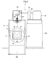
- Fig. 2 is a schematic front sectional view showing the thermal treatment furnace of the embodiment; and
- Fig. 3 is a schematic side sectional showing a modification of the invention.
- An embodiment of the present invention will be explained with reference to the drawings. A thermal treatment furnace of the embodiment is a vacuum thermal treatment furnace in which a subject to be thermally treated W in its vacuum state is heated and then, the subject to be thermally treated W is put into an
oil tank 26, or cooling fluid is stirred by afan 5 while the cooling fluid being charged therein, thereby rapidly cooling the subject to be thermally treated W. As shown in Figs. 1 and 2, the thermal treatment furnace is of a double structure including aheating chamber 1 for heating the subject to be thermally treated W, and acooling chamber 2 for cooling the subject to be thermally treated W heated in theheating chamber 1. The thermal treatment furnace is provided with athermal insulation body 12, aheater 14, avacuum exhaust system 3 and the like, as a part of theheating chamber 1, and provided with anoil tank 26, afluid introducing system 4, thefan 5 and the like; as a part of thecooling chamber 2. - More specifically, the substantially box-like
thermal insulation body 12 is disposed in afurnace barrel 11 which is an outer shell of theheating chamber 1, and disposed inside is theheater 14, thereby constituting a thermal treatment space for heating the subject to be thermally treated W. A thermalinsulating lid 13 being openable and closable is provided on the side of thecooling chamber 2 of thethermal insulation body 12. The thermalinsulating lid 13 can be opened and closed. Thethermal insulation body 12 and the thermalinsulating lid 13 are made of graphite felt for example. Thevacuum exhaust system 3 is formed by serially connecting a dispersion pump (not shown), a mechanical booster pump (not shown) and a hydraulic rotation vacuum pump (not shown) and so on, and thevacuum exhaust system 3 is connected to thefurnace barrel 11 through a valve such that they can be connected and disconnected to and from each other. Theheater 14 is a graphite heater or the like capable of heating the subject to be thermally treated W to a desired temperature. Theheater 14 is disposed at a location surrounding the subject to be thermally treated W in the thermal treatment space. - The
furnace barrel 11 is in communication with ahousing 21 which is an outer shell of thecooling chamber 2. Thefurnace barrel 11 and thehousing 21 are divided by apartition door 27 which integrally operated with the thermalinsulating lid 13. Thehousing 21 is expanded in the vertical direction. In an upper region of thehousing 21, a gas quenching space is formed by providing afluid introducing system 4 in which cooling fluid (e.g., inert gas such as N2) is charged, thefan 5 for stirring and circulating the charged cooling fluid, and aheat exchanger 22 for cooling fluid which circulates in thehousing 21. Thefluid introducing system 4 sends inert gas for cooling the subject to be thermally treated W subjected to the thermal treatment from a gas cylinder (not shown) into thehousing 21. A valve is provided in an intermediate portion of thefluid introducing system 4 of course. Thefan 5 is disposed on an upper end of thehousing 21, and adrive shaft 51 of the fan5 penetrates thehousing 21 and projects upward. Avacuum seal 23 is provided on a portion of thefan 5 where thedrive shaft 51 penetrates thehousing 21. A passage (e.g., water cooling opening in the shaft (not shown)) through which refrigerant flows may be provided in thedrive shaft 51 as means for cooling thedrive shaft 51 of thefan 5. An inlet/outlet 24 through which the subject to be thermally treated W is brought into and out from thehousing 21 is provided at a necessary location of thehousing 21. The inlet/outlet 24 is tightly closed by an opening and closingdoor 25. In addition, a lower region of thehousing 21 is formed with theoil tank 26 for accumulating quenching oil as the oil quenching space, but thisoil tank 26 is not absolutely necessary. - In this embodiment, a
thermal engine 6 which outputs driving force for driving thefan 5 is provided. Atransmitting mechanism 7 is interposed between anoutput shaft 61 of thethermal engine 6 and thedrive shaft 51 of thefan 5 to connect theoutput shaft 61 and thedrive shaft 51 with each other. - The
thermal engine 6 burns fuel to take out mechanical energy to rotate the output shaft 61 (especially internal combustion engine), but its concrete structure is not limited. It is possible to employ various thermal engines such as diesel engine, gasoline engine and gas turbine engine as thethermal engine 6 in accordance with design specification and other circumstances. Preferably, a known revolving speed control mechanism (not shown) used for an automobile and a ship is applied to control the revolving speed of theoutput shaft 61. Thethermal engine 6 is supported by apedestal 62 which is separated from thefurnace barrel 11 and thehousing 21. - The
transmitting mechanism 7 transmits rotation driving force which is outputted from thethermal engine 6 to thedrive shaft 51 of thefan 5. In this embodiment, thetransmitting mechanism 7 comprises a clutch and bevel gears. In the illustrated example, aclutch box 71 accommodating the clutch is disposed on apedestal 62, and agear box 72 accommodating the bevel gears is disposed on thehousing 21. The structure of thetransmitting mechanism 7 is not limited to the above-described structure. The clutch and the bevel gear are not absolutely necessary. Gears other than the bevel gears may be employed of course. It is also possible to use winding transmitting means such as a belt and a chain. - The reason why the
thermal engine 6 is supported by thepedestal 62 and thetransmitting mechanism 7 is interposed between thethermal engine 6 and thefan 5 is that when thethermal engine 6 is operated, its vibration can be prevented from being transmitted to thehousing 21 and thefurnace barrel 11. - Process of the quenching treatment using the vacuum thermal treatment furnace of the embodiment will be explained. The subject to be thermally treated W sent from the inlet/
outlet 24 is transferred into the thermal treatment space in theheating chamber 1 by a transfer mechanism (not shown), the thermal insulatinglid 13 of thethermal insulation body 12 and thepartition door 27 are closed, and the subject to be thermally treated W is heated. After the heating operation is completed, the thermal insulatinglid 13 and thepartition door 27 are opened, and the subject to be thermally treated W is transferred into a gas quenching space in thehousing 21 by the transfer mechanism. Then, when thethermal engine 6 is started, thefan 5 is rotated. If the revolution speed of thefan 5 reaches a predetermined revolving speed, cooling fluid, i.e., inert gas is allowed to flow into the inner chamber (i.e. , into the cooling chamber 2) of the thermal treatment furnace by thefluid introducing system 4, thefan 5 stirs the inert gas, and the subject to be thermally treated W is rapidly cooled. After the cooling operation is completed, the internal pressure in the thermal treatment furnace is reduced to the atmospheric pressure, and the subject to be thermally treated W is transferred to a portion near the inlet/outlet 24 by the transfer mechanism. When the heated subject to be thermally treated W is to be cooled, it is possible to carry out the oil quenching for bringing the subject to be thermally treated W into theoil tank 26. - According to this embodiment, the thermal treatment furnace comprises the
heating chamber 1 for heating the subject to be thermally treated W, the coolingchamber 2 into which the subject to be thermally treated W heated in theheating chamber 1 is transferred, thefan 5 for stirring fluid charged into thecooling chamber 2 for cooling the subject'to be thermally treated W, thethermal engine 6 for outputting the driving force which drives thefan 5 for a period during which the subject to be thermally treated W in thecooling chamber 2, is cooled using thefan 5 and thetransmitting mechanism 7 for transmitting the driving force which is outputted from thethermal engine 6 to thedrive shaft 51 of thefan 5. Therefore, it becomes unnecessary to provide massive power receiving equipment and power distributing equipment inside and outside of a factory. This also reduces illogical social costs for providing infrastructure whose non-operating time is longer than operating time. This is preferable for operation in various countries where the electricity circumstances are not stable as compared with Japan. - It should be note that the present invention is not limited to the above-described embodiment. For example, a single chamber thermal treatment furnace in which the
heating chamber 1 and thecooling chamber 2 are not separated from each other as shown in Fig. 3 may be employed. In this thermal treatment furnace as illustrated, thedrive shaft 51 of thefan 5 and theoutput shaft 61 of thethermal engine 6 are directed in substantially a horizontal direction, and they are substantially in parallel to each other. Accordingly, it is possible to use spur gears, helical gears or herringbone gears as an element of thetransmitting mechanism 7 which connects thedrive shaft 51 of thefan 5 and theoutput shaft 61 of thethermal engine 6 to each other. Moreover, as in this illustrated example, when thedrive shaft 51 of thefan 5 and theoutput shaft 61 of thethermal engine 6 are substantially in parallel to each other, they can directly be connected to each other without interposing thetransmitting mechanism 7. - Concrete structures of other parts are not limited to those of this embodiment, and the invention can variously be modified in a range not departing from the subject matter of the invention.
- The present invention provides a thermal treatment furnace suitable for quenching a large subject to be thermally treated, which is provided with a
thermal engine 6, and afan 5 is driven by thethermal engine 6 to stir high pressure cooling gas for a period during which the subject to be thermally treated W is cooled.
Claims (2)
- A thermal treatment furnace which heats a subject to be thermally treated, and then, cools off the subject to be thermally treated with cooling fluid being charged, comprising:an inner chamber into which the subject to be thermally treated is transferred and the cooling fluid is charged;a fan for stirring the cooling fluid charged into the inner chamber to cool the subject to be thermally treated; anda thermal engine for outputting a driving force to drive the fan for a period during which the subject to be thermally treated is cooled using the fan.
- A thermal treatment furnace which heats a subject to be thermally treated, and then, cools off the subject to be thermally treated with cooling fluid being charged, comprising:an inner chamber into which the subject to be thermally treated is transferred and the cooling fluid is charged;a fan for stirring the cooling fluid charged into the inner chamber to cool the subject to be thermally treated; anda thermal engine for outputting a driving force to drive the fan for a period during which the subject to be thermally treated is cooled using the fan; anda transmitting mechanism for transmitting the driving force which is outputted from the thermal engine to a drive shaft of the fan.
Applications Claiming Priority (1)
| Application Number | Priority Date | Filing Date | Title |
|---|---|---|---|
| JP2005068136 | 2005-03-10 |
Publications (2)
| Publication Number | Publication Date |
|---|---|
| EP1701121A2 true EP1701121A2 (en) | 2006-09-13 |
| EP1701121A3 EP1701121A3 (en) | 2007-07-25 |
Family
ID=36588914
Family Applications (1)
| Application Number | Title | Priority Date | Filing Date |
|---|---|---|---|
| EP06110907A Withdrawn EP1701121A3 (en) | 2005-03-10 | 2006-03-09 | Thermal treatment furnace |
Country Status (2)
| Country | Link |
|---|---|
| EP (1) | EP1701121A3 (en) |
| CN (1) | CN1831159A (en) |
Cited By (1)
| Publication number | Priority date | Publication date | Assignee | Title |
|---|---|---|---|---|
| CN109824368A (en) * | 2018-12-14 | 2019-05-31 | 安泰天龙钨钼科技有限公司 | A kind of method and apparatus of low energy consumption hot pressing production boron nitride-base ceramic |
Citations (1)
| Publication number | Priority date | Publication date | Assignee | Title |
|---|---|---|---|---|
| JPH10183236A (en) | 1996-12-25 | 1998-07-14 | Shimazu Mekutemu Kk | Vacuum heat treatment furnace |
Family Cites Families (1)
| Publication number | Priority date | Publication date | Assignee | Title |
|---|---|---|---|---|
| GB1274974A (en) * | 1970-04-01 | 1972-05-17 | Wild Barfield Ltd | Improvements in heat treatment furnaces |
-
2006
- 2006-03-09 EP EP06110907A patent/EP1701121A3/en not_active Withdrawn
- 2006-03-10 CN CNA2006100547644A patent/CN1831159A/en active Pending
Patent Citations (1)
| Publication number | Priority date | Publication date | Assignee | Title |
|---|---|---|---|---|
| JPH10183236A (en) | 1996-12-25 | 1998-07-14 | Shimazu Mekutemu Kk | Vacuum heat treatment furnace |
Cited By (1)
| Publication number | Priority date | Publication date | Assignee | Title |
|---|---|---|---|---|
| CN109824368A (en) * | 2018-12-14 | 2019-05-31 | 安泰天龙钨钼科技有限公司 | A kind of method and apparatus of low energy consumption hot pressing production boron nitride-base ceramic |
Also Published As
| Publication number | Publication date |
|---|---|
| CN1831159A (en) | 2006-09-13 |
| EP1701121A3 (en) | 2007-07-25 |
Similar Documents
| Publication | Publication Date | Title |
|---|---|---|
| CN110273758B (en) | Micro gas turbine generator set | |
| JP5948244B2 (en) | Apparatus and method for controlling temperature of storage battery of hybrid electric vehicle | |
| KR101786670B1 (en) | Cooling system for vehicle | |
| CN101660445A (en) | Roof-mounted muffler for system for generating electric power | |
| KR101602507B1 (en) | Ship propulsion system with use of the exhaust gas energy of large marine diesel engines | |
| US20070137909A1 (en) | Hybrid drive unit having a low-temperature circuit | |
| US20060124275A1 (en) | Power supply system for a motor vehicle | |
| US20120125278A1 (en) | Method and device for heating engine and transmission oil of a hybrid vehicle | |
| US11155171B2 (en) | Mobile electricity-generator system on vehicles | |
| EP2591217A1 (en) | Installation for cooling the drivetrain of a hybrid vehicle | |
| EP1701121A2 (en) | Thermal treatment furnace | |
| MXPA01011959A (en) | Compact power generation apparatus and method of generating energy. | |
| JP2019055649A (en) | Battery temperature control system | |
| WO2013167267A2 (en) | Range extender system having an improved cooling circuit | |
| US9181871B2 (en) | Indirectly heated gas turbine system | |
| JP3125138U (en) | Heat treatment furnace | |
| JP2009068367A (en) | Power generating device | |
| CN212563451U (en) | Multifunctional work efficiency unit | |
| JP2011127214A (en) | Heat treatment apparatus | |
| RU2736354C1 (en) | Method and device for decontaminating wastes with production of energy | |
| CN102282271A (en) | Quenching device and quenching method | |
| CN203201664U (en) | Coupled gas turbine-variable frequency power generator heat and power supply system | |
| RU2256084C1 (en) | Diesel-driven generator set | |
| KR20090059816A (en) | Cooling apparatus for hybrid vehicle motor | |
| RU2255236C1 (en) | Power plant with stirling engine, heat accumulator and intermediate heat carrier |
Legal Events
| Date | Code | Title | Description |
|---|---|---|---|
| PUAI | Public reference made under article 153(3) epc to a published international application that has entered the european phase |
Free format text: ORIGINAL CODE: 0009012 |
|
| 17P | Request for examination filed |
Effective date: 20060309 |
|
| AK | Designated contracting states |
Kind code of ref document: A2 Designated state(s): AT BE BG CH CY CZ DE DK EE ES FI FR GB GR HU IE IS IT LI LT LU LV MC NL PL PT RO SE SI SK TR |
|
| AX | Request for extension of the european patent |
Extension state: AL BA HR MK YU |
|
| PUAL | Search report despatched |
Free format text: ORIGINAL CODE: 0009013 |
|
| AK | Designated contracting states |
Kind code of ref document: A3 Designated state(s): AT BE BG CH CY CZ DE DK EE ES FI FR GB GR HU IE IS IT LI LT LU LV MC NL PL PT RO SE SI SK TR |
|
| AX | Request for extension of the european patent |
Extension state: AL BA HR MK YU |
|
| RIC1 | Information provided on ipc code assigned before grant |
Ipc: C21D 9/00 20060101ALI20070619BHEP Ipc: F27D 7/04 20060101ALI20070619BHEP Ipc: F27D 9/00 20060101ALI20070619BHEP Ipc: F27B 5/04 20060101ALI20070619BHEP Ipc: F27B 5/06 20060101AFI20060626BHEP |
|
| AKX | Designation fees paid |
Designated state(s): AT BE BG CH CY CZ DE DK EE ES FI FR GB GR HU IE IS IT LI LT LU LV MC NL PL PT RO SE SI SK TR |
|
| 17Q | First examination report despatched |
Effective date: 20090804 |
|
| GRAP | Despatch of communication of intention to grant a patent |
Free format text: ORIGINAL CODE: EPIDOSNIGR1 |
|
| INTG | Intention to grant announced |
Effective date: 20150423 |
|
| STAA | Information on the status of an ep patent application or granted ep patent |
Free format text: STATUS: THE APPLICATION IS DEEMED TO BE WITHDRAWN |
|
| 18D | Application deemed to be withdrawn |
Effective date: 20150904 |