EP1700985B1 - Lagervorrichtung und Verriegelungseinrichtung für Schiebetüre eines Kleiderschrankes - Google Patents
Lagervorrichtung und Verriegelungseinrichtung für Schiebetüre eines Kleiderschrankes Download PDFInfo
- Publication number
- EP1700985B1 EP1700985B1 EP06002945A EP06002945A EP1700985B1 EP 1700985 B1 EP1700985 B1 EP 1700985B1 EP 06002945 A EP06002945 A EP 06002945A EP 06002945 A EP06002945 A EP 06002945A EP 1700985 B1 EP1700985 B1 EP 1700985B1
- Authority
- EP
- European Patent Office
- Prior art keywords
- rolling
- sliding
- support
- frame
- hook
- Prior art date
- Legal status (The legal status is an assumption and is not a legal conclusion. Google has not performed a legal analysis and makes no representation as to the accuracy of the status listed.)
- Expired - Lifetime
Links
Images




Classifications
-
- E—FIXED CONSTRUCTIONS
- E05—LOCKS; KEYS; WINDOW OR DOOR FITTINGS; SAFES
- E05F—DEVICES FOR MOVING WINGS INTO OPEN OR CLOSED POSITION; CHECKS FOR WINGS; WING FITTINGS NOT OTHERWISE PROVIDED FOR, CONCERNED WITH THE FUNCTIONING OF THE WING
- E05F1/00—Closers or openers for wings, not otherwise provided for in this subclass
- E05F1/08—Closers or openers for wings, not otherwise provided for in this subclass spring-actuated, e.g. for horizontally sliding wings
- E05F1/16—Closers or openers for wings, not otherwise provided for in this subclass spring-actuated, e.g. for horizontally sliding wings for sliding wings
-
- E—FIXED CONSTRUCTIONS
- E05—LOCKS; KEYS; WINDOW OR DOOR FITTINGS; SAFES
- E05D—HINGES OR SUSPENSION DEVICES FOR DOORS, WINDOWS OR WINGS
- E05D15/00—Suspension arrangements for wings
- E05D15/06—Suspension arrangements for wings for wings sliding horizontally more or less in their own plane
- E05D15/0621—Details, e.g. suspension or supporting guides
- E05D15/0626—Details, e.g. suspension or supporting guides for wings suspended at the top
- E05D15/063—Details, e.g. suspension or supporting guides for wings suspended at the top on wheels with fixed axis
- E05D15/0634—Details, e.g. suspension or supporting guides for wings suspended at the top on wheels with fixed axis with height adjustment
-
- E—FIXED CONSTRUCTIONS
- E05—LOCKS; KEYS; WINDOW OR DOOR FITTINGS; SAFES
- E05F—DEVICES FOR MOVING WINGS INTO OPEN OR CLOSED POSITION; CHECKS FOR WINGS; WING FITTINGS NOT OTHERWISE PROVIDED FOR, CONCERNED WITH THE FUNCTIONING OF THE WING
- E05F5/00—Braking devices, e.g. checks; Stops; Buffers
- E05F5/003—Braking devices, e.g. checks; Stops; Buffers for sliding wings
-
- E—FIXED CONSTRUCTIONS
- E05—LOCKS; KEYS; WINDOW OR DOOR FITTINGS; SAFES
- E05D—HINGES OR SUSPENSION DEVICES FOR DOORS, WINDOWS OR WINGS
- E05D15/00—Suspension arrangements for wings
- E05D15/06—Suspension arrangements for wings for wings sliding horizontally more or less in their own plane
- E05D15/0621—Details, e.g. suspension or supporting guides
- E05D15/0626—Details, e.g. suspension or supporting guides for wings suspended at the top
- E05D15/0652—Tracks
-
- E—FIXED CONSTRUCTIONS
- E05—LOCKS; KEYS; WINDOW OR DOOR FITTINGS; SAFES
- E05F—DEVICES FOR MOVING WINGS INTO OPEN OR CLOSED POSITION; CHECKS FOR WINGS; WING FITTINGS NOT OTHERWISE PROVIDED FOR, CONCERNED WITH THE FUNCTIONING OF THE WING
- E05F3/00—Closers or openers with braking devices, e.g. checks; Construction of pneumatic or liquid braking devices
- E05F3/22—Additional arrangements for closers, e.g. for holding the wing in opened or other position
- E05F3/221—Mechanical power-locks, e.g. for holding the wing open or for free-moving zones
-
- E—FIXED CONSTRUCTIONS
- E05—LOCKS; KEYS; WINDOW OR DOOR FITTINGS; SAFES
- E05F—DEVICES FOR MOVING WINGS INTO OPEN OR CLOSED POSITION; CHECKS FOR WINGS; WING FITTINGS NOT OTHERWISE PROVIDED FOR, CONCERNED WITH THE FUNCTIONING OF THE WING
- E05F3/00—Closers or openers with braking devices, e.g. checks; Construction of pneumatic or liquid braking devices
- E05F3/22—Additional arrangements for closers, e.g. for holding the wing in opened or other position
- E05F3/227—Additional arrangements for closers, e.g. for holding the wing in opened or other position mounted at the top of wings, e.g. details related to closer housings, covers, end caps or rails therefor
-
- E—FIXED CONSTRUCTIONS
- E05—LOCKS; KEYS; WINDOW OR DOOR FITTINGS; SAFES
- E05Y—INDEXING SCHEME ASSOCIATED WITH SUBCLASSES E05D AND E05F, RELATING TO CONSTRUCTION ELEMENTS, ELECTRIC CONTROL, POWER SUPPLY, POWER SIGNAL OR TRANSMISSION, USER INTERFACES, MOUNTING OR COUPLING, DETAILS, ACCESSORIES, AUXILIARY OPERATIONS NOT OTHERWISE PROVIDED FOR, APPLICATION THEREOF
- E05Y2201/00—Constructional elements; Accessories therefor
- E05Y2201/40—Motors; Magnets; Springs; Weights; Accessories therefor
- E05Y2201/404—Function thereof
- E05Y2201/41—Function thereof for closing
- E05Y2201/412—Function thereof for closing for the final closing movement
-
- E—FIXED CONSTRUCTIONS
- E05—LOCKS; KEYS; WINDOW OR DOOR FITTINGS; SAFES
- E05Y—INDEXING SCHEME ASSOCIATED WITH SUBCLASSES E05D AND E05F, RELATING TO CONSTRUCTION ELEMENTS, ELECTRIC CONTROL, POWER SUPPLY, POWER SIGNAL OR TRANSMISSION, USER INTERFACES, MOUNTING OR COUPLING, DETAILS, ACCESSORIES, AUXILIARY OPERATIONS NOT OTHERWISE PROVIDED FOR, APPLICATION THEREOF
- E05Y2800/00—Details, accessories and auxiliary operations not otherwise provided for
- E05Y2800/20—Combinations of elements
- E05Y2800/23—Combinations of elements of elements of different categories
- E05Y2800/24—Combinations of elements of elements of different categories of springs and brakes
-
- E—FIXED CONSTRUCTIONS
- E05—LOCKS; KEYS; WINDOW OR DOOR FITTINGS; SAFES
- E05Y—INDEXING SCHEME ASSOCIATED WITH SUBCLASSES E05D AND E05F, RELATING TO CONSTRUCTION ELEMENTS, ELECTRIC CONTROL, POWER SUPPLY, POWER SIGNAL OR TRANSMISSION, USER INTERFACES, MOUNTING OR COUPLING, DETAILS, ACCESSORIES, AUXILIARY OPERATIONS NOT OTHERWISE PROVIDED FOR, APPLICATION THEREOF
- E05Y2900/00—Application of doors, windows, wings or fittings thereof
- E05Y2900/20—Application of doors, windows, wings or fittings thereof for furniture, e.g. cabinets
Definitions
- each extremity of each sliding door of the wardrobe in question comprises a rolling assembly attached thereto with means for vertical adjustment with respect to its rail and comprising a locking assembly which through a first fluid damper whose shank is connected to a downwardly retractable horizontal tilting hook guided horizontally in a body, which in its retracted position is acted upon by the charged state of a helical tension spring which is also horizontal, this locking assembly interacting with a member of the rolling assembly in such a way that it brings about locking at the end of the travel, damps it and holds it waiting for an opening force.
- a system with two sliding doors is considered in the graphic illustration accompanying this description.
- US 2005/011041 relates to an apparatus and method for wheel assemblies directed to precision roller wheel assembly for use with patio doors.
- a precision roller wheel assembly is provided, which is designed for use on a lower surface of a door, the assembly comprising a two-piece housing, the two-pieces being a mirror image of each other, for receiving at least one precision machined corrosion resistant sealed roller wheel mounted on an axle, means for mounting the assembly to a patio door, and adjustment means for vertically adjusting the assembly in its position of use.
- the means for vertical adjustment may comprise a cam gear with projections, an adjustment arm, which is sliding in the cavities formed in each of the two piece housing.
- the rolling assembly comprises an inverted "U"-shaped support which is fixed to the sliding door together with a chassis in which the wheel is mounted fitted to it and on which a vertical adjustment mechanism comprising a movable horizontal wedge positioned between the wheel chassis and the support fixed to the sliding door is fitted, this wedge being driven by the tip of a screw which is threaded through a block fixed to the said support secured to the sliding door, are known.
- the wheel chassis is assembled by sliding the same between the sides of the inverted "U"-shaped support, followed by an operation of inserting a transverse plate which simultaneously penetrates the said chassis and support without passing through more than one of the walls of the latter.
- the mounting for the block in which the vertical adjustment screw is threaded also requires the latter to be pre-positioned so that it can then be secured by a blind pin passing through only one of the walls of the support mounted on the sliding door.
- the attachment to the rail should be firm in relation to the appropriate position selected and that there should be some lateral mobility of the body of the second damper with respect to the said rail.
- this invention provides a rolling and locking device for sliding doors which while complying with the general basic arrangement for this type of product as described above has a special arrangement in that the said rolling assembly comprises a support which is mounted on the inside face of the sliding door, a frame which carries at least one wheel and which is fitted to the said support, and means for vertical adjustment through rotatory action which are placed between the said support and frame, in which the said support has an inverted "U"-shaped cross-section which is folded into right angles forming a front wall which is secured to the back of the sliding door, an upper wall and a rear wall which is fitted with at least one vertical window, the said wheel-support and frame being open at the base opposite the top guide rail thereof, as it is also open at the top where the sides of this frame transverse to the sliding door are extended at the top thereof each forming bearings which do not come into contact with the upper wall of the support, being open at their top, and conveniently cover an arc of more than 180°, this frame forming at least a flat tenon which extend
- a preferred embodiment of the invention has two vertical windows acting with corresponding flat vertical tenons located at the two extremities of the frame in the rear wall of the support with respect to the door.
- the said rear lower appendage of the wheel-supporting frame has a longitudinal profile in the form of a bridge having abutments with oblique transverse faces which converge upon each other at their extremities.
- the said tilting hook of the locking assembly comprises a resilient arm, has a recess having a longitudinal profile of oblique sides converging upon each other towards the base matching the said oblique faces of the appendage which are capable of joining them together in a loose-fitting manner, the side of these oblique sides which is closest to the tip of the hook being shorter, and this hook extending as far as its tip in an inverse hook shape thereby forming a projection towards its tip which engages with the said smaller oblique side, and a descending oblique lip.
- the said tilting hook is capable of operating between a tilted or retracted position and a non-tilted or engaging position such that, in relation to the closing movement of the siding door, in the retracted position the front oblique face of the appendage is longitudinally in line with the oblique side which is the larger of the two and closest to the coupling between the hook and the shank of the first fluid damper, while in the engaged position the appendage is received within the hook.
- Another special feature of the invention lies in the fact that with respect to the lower rail over which the sliding door rolls, there is at each extremity at least a second fluid damper of telescopic construction which is formed of a fixed or inner part, a moving or outer part and a helical compression spring placed between the two, the fixed part having a hole for attachment to the base of the wardrobe and a first "T"-shaped longitudinal fin which is slidably adjustable in a box of the said lower rail, the moving part receiving within it the spring which itself is wound about the shank of the said second damper, and this moving part has a second longitudinal fin which is slidably adjustable within the said box of the lower rail.
- This second fluid damper is to prevent pitching of the sliding door which might occur when the latter reaches the point of impact and braking, caused by the locking assembly.
- the design of this second fluid damper also makes it possible for it to be used reversibly for one or other extremity of the lower rail.
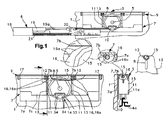
- Figure 1 is a view in the direction of cross-section I-I indicated in Figure 9 , relating only to inner sliding door (1) and in Figure 1 the components are in a relative position corresponding to one extremity of the door's travel.
- This Figure 1 includes magnified details - one, relating to the rolling assembly (3), where there is a partial upper cross-section of the rear wall (7c) and in this detail there is shown a cross-section line whose content is illustrated in another detail located in a corresponding position in which a transverse cross-section through the support (7) will be seen; in this detail three small magnifications illustrate: resilient hooking of shaft (15) onto bearing (12), the position of faceted spiral lever (16) and the appearance of the flat faces (16a) of faceted spiral lever (16).
- Figure 2 shows the frame (8) of the rolling assembly (3) in perspective to show the shape of its flat tenons (13), its bearings (12) and its rear appendage (14).
- Figures 3 and 4 show diagrammatically and sequentially the assembly insertion of shaft (15) into bearings (12) of frame (8) through a resilient snap fit.
- Figures 5, 6 and 7 show diagrammatically and sequentially the assembly of frame (8) of rolling assembly (3) into the support for the assembly.
- Figure 5 shows the rear wall (7c) of the support which has been moved resiliently by the force illustrated by the arrow shown, bringing about sufficient amplitude for support (8) shown opposite it to be inserted in accordance with the direction shown by the arrow.
- Figure 6 shows a support (8) with its flat tenons (13) partly within windows (11).
- rear wall (7c) has resiliently recovered its position and its vertical windows (11) act as a vertical guide for flat tenons (13) ensuring correct vertical adjustment movement.
- Figure 8 shows the same assembly as in Figure 7 , but with its faceted spiral lever (16) in the maximum position corresponding to the highest elevation of the door hung on this rolling assembly (3), and the magnified detail provides an illustration of the top which in this flat position tenon (13) makes with the lower edge (1 1a) of vertical window (11).
- Figure 9 is a view in transverse cross-section of an arrangement of two inner (1) and outer (2) sliding doors according to the invention.
- Figure 10 shows the frame (8) of rolling assembly (3) in Figure 1 , also including locking assembly (6), but omitting inner sliding door (1), support (7) and corresponding rail (4) and without shaft (15) with its faceted spiral levers (16).
- Figure 11 is like the transverse cross-section of rolling assembly (3) included in the magnified detail in Figure 1 , but showing the position of maximum vertical adjustment of faceted spiral levers (16).
- Figure 12 is a view similar to the principal view in Figure 1 , but only showing frame (8), with wheel (10) and appendage (14), and closure assembly (6) without body (18); all this in relation to a position immediately prior to impact of appendage (14) against hook (20) in its tilted or retracted position.
- Figures 13 and 14 are views similar to Figure 12 which illustrate the operation of locking assembly (6), in which body (16) of the latter is included.
- Figures 15 and 16 show the same as Figures 13 and 14 , but illustrate the resetting of lock assembly (6).
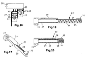
- Figure 17 is a perspective view of a second fluid damper (23) in the extended condition.
- Figure 18 is a magnification of detail XI indicated in Figure 9 .
- Figures 19 and 20 are lateral views, in orthogonal projection, showing the extended and retracted conditions of second damper (23) respectively.
- the appended plates illustrate a preferred embodiment of the invention with reference to a rolling and locking assembly for sliding wardrobe doors
- a rolling and locking assembly for sliding wardrobe doors which in those drawings take the physical form of a system ( Figure 9 ) of two inner (1) and outer (2) sliding doors which have a general basic structure comprising a rolling assembly (3) fixed thereto with vertical means for adjustment with respect to its rail (4a, 4b), and comprising a locking assembly (6) which through a first fluid damper (19) has its shank (19a) coupled to a downwardly retractable horizontal tilting hook (20) which is horizontally guided in a body (18) and which in its retracted position is acted upon by the charged condition of a helical tension spring (21) which is also horizontal, this locking assembly (6) acting together with a member of rolling assembly (3) in such a way as to bring about locking at the end of its travel, damping it and holding it awaiting an opening force.
- the device proposed can be applied to one or other end of sliding doors (1, 2), and to each of these individually.
- the detailed graphic description ( Figure 1 ) specifically relates to any rolling assembly (3), in this case the one at the right-hand extremity (seen from outside the piece of furniture) of inner sliding door (1).
- said rolling assembly (3) comprises a support (7) which is attached to the inner face of sliding door (1, 2), a frame (8) bearing at least one wheel (10) which is mounted in the said support (7), and means for vertical adjustment through rotary action (9) which are placed between the said support (7) and frame (8), where said support (7) has an inverted "U"-shaped cross-section folded into right angles forming a front wall (7a) which is attached to the back of sliding door (1, 2), an upper wall (7b) and a rear wall (7c) which is provided with at least one vertical window (11), the said frame (8) supporting the wheels being open at the bottom opposite upper rail (4a, 4b) guiding the latter, and also open at the top, where the sides of this frame (8) which are transverse to sliding door (1, 2) extend in their upper part each forming bearings (12) which are not in contact with upper wall (7b) of support (7), are open at the top and cover an arc which is conveniently greater than 180°, this frame (8) forming at least one
- Rolling assembly (3) is quick and easy to fit.
- Shaft (15) is pressure fitted into bearings (12) through resilient snap-fit locating faceted spiral levers (16) in such a way that one is on each side of its corresponding bearing (12), which has the effect of axially immobilising shaft (15); this same effect could be achieved by placing a faceted spiral lever (16) on each bearing (12) provided that both faceted spiral levers (16) are on the outer side of corresponding bearings (12), or the two are on the inner side thereof.
- Figures 1 and 12 to 14 illustrate the structure and function of locking assembly (6) according to the invention, which provides that with respect to sliding door (1, 2) appendage (14) of frame (8) is longitudinally aligned with the place where the extremity of shaft (19a) of first fluid damper (19) is connected to retractable tilting horizontal hook (20).
- oblique front face (34) of appendage (14) impacts ( Figures 12 and 13 ) against corresponding oblique side (35) of hook (20) bringing about ( Figure 14 ) tilting of the latter which through the resilient recovering action of helical tension spring (21) is displaced, travelling with shank (19a) of first damper (19) and bringing about damping and holding of the closure.
- hook (20) was in the position in Figure 14 without sliding door (1) having reached its terminal locked position, it is possible to reset the mechanism of the closure assembly because when said sliding door (1) is lifted at the end of its path front oblique face (34) of appendage (14) impacts ( Figure 15 ) on oblique lip (37) of hook (20) bringing about resilient descent of the latter which enables appendage (14) to penetrate ( Figure 16 ) within that hook (20) and when sliding door (1) is next opened the assembly is reset recovering the position in Figures 12 and 13 .
- FIG. 17 to 20 Another feature of the invention is that with respect to lower rail (22) over which sliding door (1, 2) travels, there is at each extremity at least a second fluid damper (23) of telescopic construction formed by a fixed or inner part (24), a moving or outer part (25) and a helical compression spring (26) placed between the two, fixed part (24) having a hole (27) for attachment to the floor (28) of the wardrobe and a first longitudinal "T"-shaped fin (29) which is slidably adjusted in a box (30) of the said lower rail (22), moving part (25) housing within it spring (26) which in turn surrounds shank (31) of said second damper (23), and this moving part (25) has a second longitudinal fin (32) which is slidably adjustable in said box (30) of lower rail (22).
- a second fluid damper (23) of telescopic construction formed by a fixed or inner part (24), a moving or outer part (25) and a helical compression spring (26) placed between the two, fixed part (24) having a
- This mechanism compensates for any pitching tendency of sliding door (1) to impact at the top against locking assembly (6); this mechanism is reversible and has a firm and reliable mounting thanks to the slidably adjustable location of first (29) and second (32) longitudinal fins in corresponding box (30) of lower rail (22).
- damping and locking system was at the top and the additional damping system was at the bottom.
- damping system could be one piece with the door or not within the profile.
Landscapes
- Engineering & Computer Science (AREA)
- Mechanical Engineering (AREA)
- Support Devices For Sliding Doors (AREA)
- Closing And Opening Devices For Wings, And Checks For Wings (AREA)
- Drawers Of Furniture (AREA)
- Lock And Its Accessories (AREA)
- Wing Frames And Configurations (AREA)
Claims (8)
- Roll- und Feststelleinrichtung für Schrankschiebetüren, welche für jeden Endpunkt einer jeden Schiebetür (1, 2) einen Rollaufbau (3) umfasst, der daran befestigt ist und Mittel zur vertikalen Justierung in Bezug auf deren Schiene (4a, 4b) aufweist, und einen Feststellaufbau (6) umfasst, welcher durch einen ersten Fluiddämpfer (19) dessen Schaft (19a) mit einem nach unten schwenkbaren horizontalen Kipphaken (20) gekoppelt ist und der in einem Körper (18) horizontal geführt wird, und der in dessen zurückgezogener Position durch den belasteten Zustand einer helixförmigen Zugfeder (21) beansprucht wird, die ebenfalls horizontal ist, wobei dieser Feststellaufbau (6) mit einem Element des Rollaufbaus (3) in derartiger Weise in Wechselwirkung tritt, dass er ein Feststellen am Ende seines Wegs zur Folge hat, ihn dämpft und ihn eine öffnende Kraft erwartend hält, dadurch gekennzeichnet, dass der Rollaufbau (3) einen mit der Innenseite der Schiebetür (1, 2) verankerten Träger (7) umfasst, einen Rahmen (8), der mindestens ein Rad (10) trägt, der auf dem Träger (7) installiert ist, und Mittel zur vertikalen Justierung durch Drehwirkung (9), die zwischen dem Träger (7) und dem Rahmen (8) lokalisiert sind, wobei der Träger (7) einen Querschnitt einer umgekehrten "U"-Form aufweist, die in rechte Winkel gefaltet ist um eine an die Rückseite der Schiebetür (1, 2) angebrachte vordere Wandung (7a), eine obere Wandung (7b) und eine tiefere Wandung (7c) zu bilden, welche mit mindestens einem vertikalen Fenster (11) bereitgestellt ist, wobei der Rad tragende Rahmen (8) an der Bodenseite gegenüber der oberen Schiene (4a, 4b) offen ist, um die selbigen zu führen, und ebenfalls an der Oberseite offen ist, wo sich die Seiten dieses Rahmens (8), die quer zur Schiebetür (1, 2) verlaufen, jeweils an der Oberseite erstrecken, um Lager (12) zu bilden, die mit der oberen Wandung (7b) des Trägers (7) nicht in Kontakt kommen, an der Oberseite offen sind und einen Bogen bilden, der in geeigneter Weise größer als 180° ist, wobei der Rahmen (8) mindestens einen flachen Zapfen (13) bildet, der sich vertikal mit einer Breite erstreckt, die in Bezug auf ein entsprechendes vertikales Fenster (11) gleitfähig justiert ist, und eine Höhe aufweist, die in geeigneter Weise geringer ist als die des vertikalen Fensters (11), und wobei der Rahmen (8) einen hinteren tieferen Anhang (14) aufnimmt, der sich über die hintere Wandung (7c) des Trägers (7) erstreckt und der gemeinsam mit dem Feststellaufbau (6) wirkt, und wobei die Mittel zur vertikalen Justierung durch Dreheinwirkung einen Schaft (15) umfassen, dessen Durchmesser in Drehung mit einem Festziehen auf den Lagern (12) justiert wird und darin durch einen federnden Schnappverschluss eindringen kann, wobei dieser Schaft (15) in Verbindung mit den Lagern (12) facettierte, spiralförmige Hebel (16) mit polygonalem Profil aufweist, die eine Abfolge von Facetten (16a) bilden, die in Verbindung mit der oberen Wandung (7b) des Trägers (7) wirken, während die Endpunkte des Schafts (15) jeweils in Schraubenköpfen (17) enden, die sich longitudinal von dem Träger (7) erstrecken.
- Roll- und Feststelleinrichtung für Schrankschiebetüren gemäß Anspruch 1, dadurch gekennzeichnet, dass der Anhang (14) ein Längsprofil in der Form einer Brücke mit Widerlagern (33) aufweist, die schiefe, quer verlaufende Seiten (34) aufweisen, die an deren Endpunkten aufeinander konvergieren.
- Roll- und Feststelleinrichtung für Schrankschiebetüren gemäß der vorstehenden Ansprüche, dadurch gekennzeichnet, dass die hintere Wandung (7c) des Trägers (7) in Bezug auf die Tür zwei vertikale Fenster (11) aufweist, die mit den entsprechenden flachen vertikalen Zapfen (13) zusammenwirken, die an den Endpunkten des Rahmens (8) lokalisiert sind.
- Roll- und Feststelleinrichtung für Schrankschiebetüren gemäß der vorstehenden Ansprüche, dadurch gekennzeichnet, dass es in einer bevorzugten Ausführungsform in Bezug zu jedem Lager (12) des Rahmens (8) zwei der facettierten spiralförmigen Hebel (16) gibt, die Zwillinge sind und einer an jeder Seite der Lager (12) lokalisiert ist, obwohl die Erfindung ebenfalls lediglich einen facettierten zentralen Hebel umfassen kann.
- Roll- und Feststelleinrichtung für Schrankschiebetüren gemäß der vorstehenden Ansprüche, dadurch gekennzeichnet, dass die Position der größten Höhe des facettierten spiralförmigen Hebels (16) (maximale Türhöhe) mit der Oberseite von mindestens einem flachen Zapfen (13) und mit dem unteren Rand (11a) von mindestens einem vertikalen Fenster (11) übereinstimmt.
- Roll- und Feststelleinrichtung für Schrankschiebetüren gemäß der vorstehenden Ansprüche, dadurch gekennzeichnet, dass der Kipphaken (20) aus einem federnden Arm gebildet ist, eine Aussparung mit einem Längsprofil mit schrägen Seiten (35) aufweist, die zusammen nach unten konvergieren, die abgestimmt sind mit den schrägen Oberflächen (34) des Anhangs (14) und diese gemeinsam in einer losen Passung aufnehmen können, wobei von den schrägen Seiten (35) die eine, die nahe zu der Spitze des Hakens (20) lokalisiert ist, die Kürzere ist, und sich dieser Haken (20) von seiner Spitze in der Form eines umgekehrten Hakens erstreckt, welcher bis zu seiner Spitze und in dieser Reihenfolge Oberseite (36) bildet, die in Eingriff kommt mit der kleineren schrägen Seite (35) und einer schrägen absteigenden Lippe (37), und wobei der Kipphaken (20) betrieben werden kann zwischen einer schräg gestellten oder zurückgezogenen Position oder einer nicht schräg gestellten oder sich in Eingriff befindlichen Position, so dass in Bezug auf die Schließbewegung der Schiebtür (1, 2) in der zurückgezogenen Position die schräge Vorderseite (34) des Ansatzes (14) longitudinal in Reihe ist mit dem schrägen Rand (35), welcher der größere der beiden und der nähere zu dem Koppeln des Hakens (20) mit dem Schaft (19a) des ersten Fluiddämpfers (19) ist, wobei in dieser im Eingriff befindlichen Position der Ansatz (14) in dem Haken (20) aufgenommen ist.
- Roll- und Feststelleinrichtung für Schrankschiebetüren gemäß der vorstehenden Ansprüche, dadurch gekennzeichnet, dass in Bezug auf die Bewegung der Schiebetür (1, 2) der Ansatz (14) des Rahmens (8) direkt longitudinal in Reihe mit dem Endpunkt des Schafts (19a) des ersten Fluiddämpfers (19) ist, der an den schwenkbaren horizontalen Kipphaken (20) gekoppelt ist.
- Roll- und Feststelleinrichtung für Schrankschiebetüren gemäß der vorstehenden Ansprüche, dadurch gekennzeichnet, dass sich in Bezug auf die tiefere Schiene (22) über welche die Schiebetür (1, 2) läuft, an jedem Endpunkt mindestens ein zweiter Fluiddämpfer (23) mit Teleskopkonstruktion befindet, die gebildet ist aus einem fixierten oder inneren Teil (24), einem sich bewegenden oder äußeren Teil (25) und einer zwischen den beiden lokalisierten helixförmigen Druckfeder (26), wobei der fixierte Teil (24) eine Öffnung (27) zum Anbringen an den Boden (28) des Schranks und eine erste "T"-förmige Längsflosse (29) aufweist, die in einem Kasten (30) der tieferen Schiene (22) gleitfähig justiert werden kann, wobei der sich bewegende Teil (25) in sich eine Feder (26) aufnimmt, die wiederum den Schaft (31) des zweiten Dämpfers (23) umgibt und dieser sich bewegende Teil (25) eine zweite Längsflosse (32) aufweist, die in dem Kasten (30) der tieferen Schiene (22) eine Gleitjustierung aufweist.
Applications Claiming Priority (2)
| Application Number | Priority Date | Filing Date | Title |
|---|---|---|---|
| ES200500433A ES2285888B1 (es) | 2005-02-25 | 2005-02-25 | Dispositivo de rodadura y cierre para puertas correderas de armarios. |
| ES200503126A ES2285924B1 (es) | 2005-02-25 | 2005-12-20 | Mejoras en la patente de invencion n. p-200500433 por "dispositivo de rodadura y cierre para puertas correderas de armarios". |
Publications (2)
| Publication Number | Publication Date |
|---|---|
| EP1700985A1 EP1700985A1 (de) | 2006-09-13 |
| EP1700985B1 true EP1700985B1 (de) | 2008-04-23 |
Family
ID=36581829
Family Applications (1)
| Application Number | Title | Priority Date | Filing Date |
|---|---|---|---|
| EP06002945A Expired - Lifetime EP1700985B1 (de) | 2005-02-25 | 2006-02-14 | Lagervorrichtung und Verriegelungseinrichtung für Schiebetüre eines Kleiderschrankes |
Country Status (4)
| Country | Link |
|---|---|
| EP (1) | EP1700985B1 (de) |
| AT (1) | ATE393282T1 (de) |
| DE (1) | DE602006000959D1 (de) |
| ES (1) | ES2302263T3 (de) |
Cited By (1)
| Publication number | Priority date | Publication date | Assignee | Title |
|---|---|---|---|---|
| CN108860666A (zh) * | 2018-06-26 | 2018-11-23 | 中国人民解放军国防科技大学 | 在轨服务加注口开门机构 |
Families Citing this family (17)
| Publication number | Priority date | Publication date | Assignee | Title |
|---|---|---|---|---|
| ITMI20072168A1 (it) * | 2007-11-14 | 2009-05-15 | Agostino Ferrari Spa | "sistema di chiusura controllata per elementi scorrevoli di mobilio" |
| BE1017959A3 (nl) * | 2008-01-16 | 2010-02-02 | Louage En Wisselinck Nv | Sluitinrichting voor een schuifdeur. |
| ITRM20080320A1 (it) * | 2008-06-18 | 2009-12-19 | Sliding S R L | Dispositivo di richiamo e smorzamento per porte scorrevoli, cassetti e similari |
| IT1392066B1 (it) * | 2008-10-13 | 2012-02-09 | Agostino Ferrari Spa | Dispositivo ammortizzante per elementi scorrevoli di elementi di arredamento |
| DE102008051360A1 (de) * | 2008-10-15 | 2010-05-12 | Karl Simon Gmbh & Co. Kg | Einzugsvorrichtung |
| DE202008014529U1 (de) | 2008-11-03 | 2010-03-18 | Hettich-Heinze Gmbh & Co. Kg | Führungsvorrichtung für Schiebetüren |
| IT1396427B1 (it) | 2009-10-14 | 2012-11-23 | Caimi Export Spa | Dispositivo ammortizzatore particolarmente per articoli di mobilio. |
| IT1402039B1 (it) * | 2010-10-15 | 2013-08-28 | Caimi Export Spa | Dispositivo di scorrimento per elementi scorrevoli di mobili |
| DE102011015911B4 (de) * | 2011-04-01 | 2013-08-01 | Günther Zimmer | Schiebetürbeschlagseinheit und Schrank mit einer derartigen Einheit |
| JP5180354B2 (ja) * | 2011-08-11 | 2013-04-10 | ファナック株式会社 | 工作機械のスライドドアの衝撃吸収機構 |
| ITMI20120433A1 (it) * | 2012-03-20 | 2013-09-21 | Caimi Export Spa | Dispositivo di smorzamento di ante scorrevoli |
| JP6184228B2 (ja) * | 2013-07-29 | 2017-08-23 | コクヨ株式会社 | 収納具及び天板付き家具 |
| DE102016006101A1 (de) * | 2016-05-20 | 2017-11-23 | Weinor Gmbh & Co. Kg | Schiebetürsystem mit Dämpferanordnung |
| ES2592525B1 (es) | 2016-06-23 | 2017-09-06 | Oscar Torrabias Cantal | Pinza compacta para puertas correderas de cristal con amortiguador incorporado |
| CN108086839B (zh) * | 2017-12-08 | 2023-05-02 | 广东东泰五金精密制造有限公司 | 一种家具弹性装置的简便拆装机构 |
| CN113681344A (zh) * | 2021-09-28 | 2021-11-23 | 黑马赵防护技术(青岛)有限公司 | 新型整体壁式防护系统 |
| CN113928451A (zh) * | 2021-11-25 | 2022-01-14 | 徐州汉邦车业有限公司 | 一种便于组装的三轮车驾驶室 |
Family Cites Families (3)
| Publication number | Priority date | Publication date | Assignee | Title |
|---|---|---|---|---|
| FR2441041A1 (fr) * | 1978-11-13 | 1980-06-06 | Novobat Sarl | Perfectionnements aux chariots pour vantail coulissant |
| FR2485608A1 (fr) * | 1980-06-30 | 1981-12-31 | Ferco Int Usine Ferrures | Ferrure de fenetre coulissante, porte coulissante ou analogue |
| US20050011041A1 (en) * | 2003-06-18 | 2005-01-20 | Ness John T. | Precision machined roller wheel assembly |
-
2006
- 2006-02-14 DE DE602006000959T patent/DE602006000959D1/de not_active Expired - Lifetime
- 2006-02-14 AT AT06002945T patent/ATE393282T1/de not_active IP Right Cessation
- 2006-02-14 EP EP06002945A patent/EP1700985B1/de not_active Expired - Lifetime
- 2006-02-14 ES ES06002945T patent/ES2302263T3/es not_active Expired - Lifetime
Cited By (2)
| Publication number | Priority date | Publication date | Assignee | Title |
|---|---|---|---|---|
| CN108860666A (zh) * | 2018-06-26 | 2018-11-23 | 中国人民解放军国防科技大学 | 在轨服务加注口开门机构 |
| CN108860666B (zh) * | 2018-06-26 | 2020-01-07 | 中国人民解放军国防科技大学 | 在轨服务加注口开门机构 |
Also Published As
| Publication number | Publication date |
|---|---|
| ES2302263T3 (es) | 2008-07-01 |
| EP1700985A1 (de) | 2006-09-13 |
| DE602006000959D1 (de) | 2008-06-05 |
| ATE393282T1 (de) | 2008-05-15 |
Similar Documents
| Publication | Publication Date | Title |
|---|---|---|
| EP1700985A1 (de) | Lagervorrichtung und Verriegelungseinrichtung für Schiebetüre eines Kleiderschrankes | |
| JP4468591B2 (ja) | 緩衝装置 | |
| EP2781677B1 (de) | Laufrollenanordnung | |
| US8336972B2 (en) | Displacement device for pivotally held separation elements and article of furniture | |
| CN104453523B (zh) | 用于滑动元件的可调节的安装装置和滑动装置 | |
| EP4249709B1 (de) | Schloss in kastenbauweise | |
| EP0648908A1 (de) | Obenliegender Türhalter | |
| EP1640537B1 (de) | Stossdämpfende und stabilisierende Stoppvorrichting für Schiebetüren und -läden | |
| WO2011014115A1 (en) | Device at a control mechanism for a window fixture at a turnable window | |
| EP0040167B1 (de) | Einstellbare Anzugsriegelverschlussanordnung | |
| JP4531605B2 (ja) | 吊り下げ式伸縮扉 | |
| JP3160669B2 (ja) | 引戸のガイド装置 | |
| JPH1162365A (ja) | 吊戸の吊垂移動装置 | |
| JP2510620B2 (ja) | ガレ―ジ扉 | |
| KR200269331Y1 (ko) | 창문용 호차 | |
| JP2909047B2 (ja) | 戸車装置及び引戸の係止装置 | |
| JP2005200959A (ja) | ノンレール式引戸型ゲート | |
| JP3096885B2 (ja) | 連動折り戸用の走行体とヒンジの着脱装置 | |
| JP4822723B2 (ja) | 吊り下げ式伸縮扉 | |
| JP4684704B2 (ja) | 吊り下げ式伸縮扉 | |
| MXPA00009003A (en) | Buffer device | |
| JP4777678B2 (ja) | 吊り下げ式伸縮扉 | |
| AU2014221269A1 (en) | Bogey assembly | |
| NZ531713A (en) | Improved panel installation system | |
| HK1208060B (en) | Adjustable mounting device for a sliding element and sliding device |
Legal Events
| Date | Code | Title | Description |
|---|---|---|---|
| PUAI | Public reference made under article 153(3) epc to a published international application that has entered the european phase |
Free format text: ORIGINAL CODE: 0009012 |
|
| AK | Designated contracting states |
Kind code of ref document: A1 Designated state(s): AT BE BG CH CY CZ DE DK EE ES FI FR GB GR HU IE IS IT LI LT LU LV MC NL PL PT RO SE SI SK TR |
|
| AX | Request for extension of the european patent |
Extension state: AL BA HR MK YU |
|
| 17P | Request for examination filed |
Effective date: 20061120 |
|
| 17Q | First examination report despatched |
Effective date: 20061221 |
|
| AKX | Designation fees paid |
Designated state(s): AT BE BG CH CY CZ DE DK EE ES FI FR GB GR HU IE IS IT LI LT LU LV MC NL PL PT RO SE SI SK TR |
|
| GRAP | Despatch of communication of intention to grant a patent |
Free format text: ORIGINAL CODE: EPIDOSNIGR1 |
|
| GRAS | Grant fee paid |
Free format text: ORIGINAL CODE: EPIDOSNIGR3 |
|
| GRAA | (expected) grant |
Free format text: ORIGINAL CODE: 0009210 |
|
| AK | Designated contracting states |
Kind code of ref document: B1 Designated state(s): AT BE BG CH CY CZ DE DK EE ES FI FR GB GR HU IE IS IT LI LT LU LV MC NL PL PT RO SE SI SK TR |
|
| REG | Reference to a national code |
Ref country code: GB Ref legal event code: FG4D |
|
| REG | Reference to a national code |
Ref country code: CH Ref legal event code: EP |
|
| REF | Corresponds to: |
Ref document number: 602006000959 Country of ref document: DE Date of ref document: 20080605 Kind code of ref document: P |
|
| REG | Reference to a national code |
Ref country code: IE Ref legal event code: FG4D Free format text: LANGUAGE OF EP DOCUMENT: FRENCH |
|
| REG | Reference to a national code |
Ref country code: ES Ref legal event code: FG2A Ref document number: 2302263 Country of ref document: ES Kind code of ref document: T3 |
|
| PG25 | Lapsed in a contracting state [announced via postgrant information from national office to epo] |
Ref country code: SI Free format text: LAPSE BECAUSE OF FAILURE TO SUBMIT A TRANSLATION OF THE DESCRIPTION OR TO PAY THE FEE WITHIN THE PRESCRIBED TIME-LIMIT Effective date: 20080423 |
|
| NLV1 | Nl: lapsed or annulled due to failure to fulfill the requirements of art. 29p and 29m of the patents act | ||
| PG25 | Lapsed in a contracting state [announced via postgrant information from national office to epo] |
Ref country code: PT Free format text: LAPSE BECAUSE OF FAILURE TO SUBMIT A TRANSLATION OF THE DESCRIPTION OR TO PAY THE FEE WITHIN THE PRESCRIBED TIME-LIMIT Effective date: 20080923 Ref country code: NL Free format text: LAPSE BECAUSE OF FAILURE TO SUBMIT A TRANSLATION OF THE DESCRIPTION OR TO PAY THE FEE WITHIN THE PRESCRIBED TIME-LIMIT Effective date: 20080423 Ref country code: BG Free format text: LAPSE BECAUSE OF FAILURE TO SUBMIT A TRANSLATION OF THE DESCRIPTION OR TO PAY THE FEE WITHIN THE PRESCRIBED TIME-LIMIT Effective date: 20080723 Ref country code: FI Free format text: LAPSE BECAUSE OF FAILURE TO SUBMIT A TRANSLATION OF THE DESCRIPTION OR TO PAY THE FEE WITHIN THE PRESCRIBED TIME-LIMIT Effective date: 20080423 |
|
| PG25 | Lapsed in a contracting state [announced via postgrant information from national office to epo] |
Ref country code: LV Free format text: LAPSE BECAUSE OF FAILURE TO SUBMIT A TRANSLATION OF THE DESCRIPTION OR TO PAY THE FEE WITHIN THE PRESCRIBED TIME-LIMIT Effective date: 20080423 Ref country code: PL Free format text: LAPSE BECAUSE OF FAILURE TO SUBMIT A TRANSLATION OF THE DESCRIPTION OR TO PAY THE FEE WITHIN THE PRESCRIBED TIME-LIMIT Effective date: 20080423 Ref country code: AT Free format text: LAPSE BECAUSE OF FAILURE TO SUBMIT A TRANSLATION OF THE DESCRIPTION OR TO PAY THE FEE WITHIN THE PRESCRIBED TIME-LIMIT Effective date: 20080423 |
|
| PG25 | Lapsed in a contracting state [announced via postgrant information from national office to epo] |
Ref country code: IS Free format text: LAPSE BECAUSE OF FAILURE TO SUBMIT A TRANSLATION OF THE DESCRIPTION OR TO PAY THE FEE WITHIN THE PRESCRIBED TIME-LIMIT Effective date: 20080823 |
|
| ET | Fr: translation filed | ||
| PG25 | Lapsed in a contracting state [announced via postgrant information from national office to epo] |
Ref country code: LT Free format text: LAPSE BECAUSE OF FAILURE TO SUBMIT A TRANSLATION OF THE DESCRIPTION OR TO PAY THE FEE WITHIN THE PRESCRIBED TIME-LIMIT Effective date: 20080423 Ref country code: SE Free format text: LAPSE BECAUSE OF FAILURE TO SUBMIT A TRANSLATION OF THE DESCRIPTION OR TO PAY THE FEE WITHIN THE PRESCRIBED TIME-LIMIT Effective date: 20080723 Ref country code: DK Free format text: LAPSE BECAUSE OF FAILURE TO SUBMIT A TRANSLATION OF THE DESCRIPTION OR TO PAY THE FEE WITHIN THE PRESCRIBED TIME-LIMIT Effective date: 20080423 Ref country code: CZ Free format text: LAPSE BECAUSE OF FAILURE TO SUBMIT A TRANSLATION OF THE DESCRIPTION OR TO PAY THE FEE WITHIN THE PRESCRIBED TIME-LIMIT Effective date: 20080423 |
|
| PG25 | Lapsed in a contracting state [announced via postgrant information from national office to epo] |
Ref country code: RO Free format text: LAPSE BECAUSE OF FAILURE TO SUBMIT A TRANSLATION OF THE DESCRIPTION OR TO PAY THE FEE WITHIN THE PRESCRIBED TIME-LIMIT Effective date: 20080423 Ref country code: SK Free format text: LAPSE BECAUSE OF FAILURE TO SUBMIT A TRANSLATION OF THE DESCRIPTION OR TO PAY THE FEE WITHIN THE PRESCRIBED TIME-LIMIT Effective date: 20080423 Ref country code: BE Free format text: LAPSE BECAUSE OF FAILURE TO SUBMIT A TRANSLATION OF THE DESCRIPTION OR TO PAY THE FEE WITHIN THE PRESCRIBED TIME-LIMIT Effective date: 20080423 |
|
| PLBE | No opposition filed within time limit |
Free format text: ORIGINAL CODE: 0009261 |
|
| STAA | Information on the status of an ep patent application or granted ep patent |
Free format text: STATUS: NO OPPOSITION FILED WITHIN TIME LIMIT |
|
| 26N | No opposition filed |
Effective date: 20090126 |
|
| PG25 | Lapsed in a contracting state [announced via postgrant information from national office to epo] |
Ref country code: DE Free format text: LAPSE BECAUSE OF FAILURE TO SUBMIT A TRANSLATION OF THE DESCRIPTION OR TO PAY THE FEE WITHIN THE PRESCRIBED TIME-LIMIT Effective date: 20080724 Ref country code: EE Free format text: LAPSE BECAUSE OF FAILURE TO SUBMIT A TRANSLATION OF THE DESCRIPTION OR TO PAY THE FEE WITHIN THE PRESCRIBED TIME-LIMIT Effective date: 20080423 |
|
| PG25 | Lapsed in a contracting state [announced via postgrant information from national office to epo] |
Ref country code: MC Free format text: LAPSE BECAUSE OF NON-PAYMENT OF DUE FEES Effective date: 20090228 |
|
| PGFP | Annual fee paid to national office [announced via postgrant information from national office to epo] |
Ref country code: FR Payment date: 20081211 Year of fee payment: 4 |
|
| PG25 | Lapsed in a contracting state [announced via postgrant information from national office to epo] |
Ref country code: IE Free format text: LAPSE BECAUSE OF NON-PAYMENT OF DUE FEES Effective date: 20090214 |
|
| REG | Reference to a national code |
Ref country code: ES Ref legal event code: FD2A Effective date: 20090216 |
|
| PG25 | Lapsed in a contracting state [announced via postgrant information from national office to epo] |
Ref country code: ES Free format text: LAPSE BECAUSE OF NON-PAYMENT OF DUE FEES Effective date: 20090216 |
|
| REG | Reference to a national code |
Ref country code: CH Ref legal event code: PL |
|
| GBPC | Gb: european patent ceased through non-payment of renewal fee |
Effective date: 20100214 |
|
| PG25 | Lapsed in a contracting state [announced via postgrant information from national office to epo] |
Ref country code: LI Free format text: LAPSE BECAUSE OF NON-PAYMENT OF DUE FEES Effective date: 20100228 Ref country code: CH Free format text: LAPSE BECAUSE OF NON-PAYMENT OF DUE FEES Effective date: 20100228 Ref country code: GR Free format text: LAPSE BECAUSE OF FAILURE TO SUBMIT A TRANSLATION OF THE DESCRIPTION OR TO PAY THE FEE WITHIN THE PRESCRIBED TIME-LIMIT Effective date: 20080724 |
|
| REG | Reference to a national code |
Ref country code: FR Ref legal event code: ST Effective date: 20101029 |
|
| PG25 | Lapsed in a contracting state [announced via postgrant information from national office to epo] |
Ref country code: FR Free format text: LAPSE BECAUSE OF NON-PAYMENT OF DUE FEES Effective date: 20100301 |
|
| PG25 | Lapsed in a contracting state [announced via postgrant information from national office to epo] |
Ref country code: GB Free format text: LAPSE BECAUSE OF NON-PAYMENT OF DUE FEES Effective date: 20100214 |
|
| PG25 | Lapsed in a contracting state [announced via postgrant information from national office to epo] |
Ref country code: LU Free format text: LAPSE BECAUSE OF NON-PAYMENT OF DUE FEES Effective date: 20090214 |
|
| PG25 | Lapsed in a contracting state [announced via postgrant information from national office to epo] |
Ref country code: HU Free format text: LAPSE BECAUSE OF FAILURE TO SUBMIT A TRANSLATION OF THE DESCRIPTION OR TO PAY THE FEE WITHIN THE PRESCRIBED TIME-LIMIT Effective date: 20081024 |
|
| PG25 | Lapsed in a contracting state [announced via postgrant information from national office to epo] |
Ref country code: TR Free format text: LAPSE BECAUSE OF FAILURE TO SUBMIT A TRANSLATION OF THE DESCRIPTION OR TO PAY THE FEE WITHIN THE PRESCRIBED TIME-LIMIT Effective date: 20080423 |
|
| PG25 | Lapsed in a contracting state [announced via postgrant information from national office to epo] |
Ref country code: CY Free format text: LAPSE BECAUSE OF FAILURE TO SUBMIT A TRANSLATION OF THE DESCRIPTION OR TO PAY THE FEE WITHIN THE PRESCRIBED TIME-LIMIT Effective date: 20080423 |
|
| PGFP | Annual fee paid to national office [announced via postgrant information from national office to epo] |
Ref country code: IT Payment date: 20090228 Year of fee payment: 4 |