EP1700969A2 - Prefabricated self-supporting partition wall - Google Patents
Prefabricated self-supporting partition wall Download PDFInfo
- Publication number
- EP1700969A2 EP1700969A2 EP06380033A EP06380033A EP1700969A2 EP 1700969 A2 EP1700969 A2 EP 1700969A2 EP 06380033 A EP06380033 A EP 06380033A EP 06380033 A EP06380033 A EP 06380033A EP 1700969 A2 EP1700969 A2 EP 1700969A2
- Authority
- EP
- European Patent Office
- Prior art keywords
- self
- modules
- edges
- supporting
- blades
- Prior art date
- Legal status (The legal status is an assumption and is not a legal conclusion. Google has not performed a legal analysis and makes no representation as to the accuracy of the status listed.)
- Withdrawn
Links
Images
Classifications
-
- E—FIXED CONSTRUCTIONS
- E04—BUILDING
- E04C—STRUCTURAL ELEMENTS; BUILDING MATERIALS
- E04C2/00—Building elements of relatively thin form for the construction of parts of buildings, e.g. sheet materials, slabs, or panels
- E04C2/02—Building elements of relatively thin form for the construction of parts of buildings, e.g. sheet materials, slabs, or panels characterised by specified materials
- E04C2/10—Building elements of relatively thin form for the construction of parts of buildings, e.g. sheet materials, slabs, or panels characterised by specified materials of wood, fibres, chips, vegetable stems, or the like; of plastics; of foamed products
- E04C2/24—Building elements of relatively thin form for the construction of parts of buildings, e.g. sheet materials, slabs, or panels characterised by specified materials of wood, fibres, chips, vegetable stems, or the like; of plastics; of foamed products laminated and composed of materials covered by two or more of groups E04C2/12, E04C2/16, E04C2/20
- E04C2/243—Building elements of relatively thin form for the construction of parts of buildings, e.g. sheet materials, slabs, or panels characterised by specified materials of wood, fibres, chips, vegetable stems, or the like; of plastics; of foamed products laminated and composed of materials covered by two or more of groups E04C2/12, E04C2/16, E04C2/20 one at least of the material being insulating
-
- E—FIXED CONSTRUCTIONS
- E04—BUILDING
- E04C—STRUCTURAL ELEMENTS; BUILDING MATERIALS
- E04C2/00—Building elements of relatively thin form for the construction of parts of buildings, e.g. sheet materials, slabs, or panels
- E04C2/30—Building elements of relatively thin form for the construction of parts of buildings, e.g. sheet materials, slabs, or panels characterised by the shape or structure
- E04C2/38—Building elements of relatively thin form for the construction of parts of buildings, e.g. sheet materials, slabs, or panels characterised by the shape or structure with attached ribs, flanges, or the like, e.g. framed panels
- E04C2/386—Building elements of relatively thin form for the construction of parts of buildings, e.g. sheet materials, slabs, or panels characterised by the shape or structure with attached ribs, flanges, or the like, e.g. framed panels with a frame of unreconstituted or laminated wood
Definitions
- the present invention relates to a self-supporting prefabricated partition, essentially characterized in that it consists of a set of standardized dimensions modules that allow the configuration and rapid assembly of partitions in the required dimensions and shapes, these modules being formed by a set of bouvettées parts and therefore perfectly united to each other, provided with a rigid internal element with particular physico-technical characteristics, as well as various components which will give to the unit modules mentioned here the rigidity essential for them to be used like self-supporting elements, with sufficient rigidity and deformability.
- prefabricated elements in the construction industry has been a successful practice for a very long time, applications have improved by using elements and materials that have given consistency to said prefabricated, while increasing the characteristics the same, their resistance to the different forces and pressures to which the building elements are subjected and allowing, in short, to use them more generally with the economic advantages that all this has represented.
- the self-supporting prefabricated partition according to the invention consists of a series of modules (1), which, having standardized dimensions appropriate to the standards used in the construction, can be quickly and easily located in their location, requiring a minimal operations and manipulations such as sawing and drilling to adapt them to the final measurements.
- Each of these modules (1) is formed of two faces, outer and inner, consisting of vertical planks knuckle (2), preferably made of high quality wood, with a moisture content of between 12 and 15% in the purpose of offering an increased resistance to the action of external agents, as well as the possibility of receiving on its surface finishing products according to the decorative requirements of the environment and the place, such as waxes, paints, varnishes, lacquers or the like.
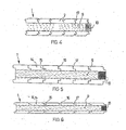
- Each of these tongue-and-groove blades (2) has, on one of its extreme edges, a rectangular section recess (3), arranged in longitudinal slot mode, presenting a flat zone (4) on one side and an inclined flat zone. (5) growing towards the own cut (3) on the other side.
- the tongue-and-groove blade has a salient (6) with a rectangular cross-section and a rounded end, which on one side has a flat horizontal zone (7) and on the other side an inclined zone (8) extending towards the wall of the salient (6) and slightly bounded. Faces side of the blade (2) are flat and parallel to each other.
- the salient (6) will have a size identical to the width of the longitudinal slot (3) in order to be highly nested and ensure the removability of the blades (2) already located one after the other.
- each of the blades being made according to the above described and as shown in Figures 1 and 4, they will unite to each other taking advantage of their bouvetage, introducing the salient (6) inside the notch (3) of the contiguous blade (2), and thus successively to complete the entire module (1), according to the dimensioning that has been established.
- the module (1) remains completed once two sets of blades (2) have been prepared, strongly united between them, placing them parallel and leaving a separation already predetermined between them, separation which will be filled in its entirety with injected polyurethane, constituting in said interior a rigid and resistant mass (9), low weight and physicochemical characteristics able to offer the whole a thermal and acoustic insulation, as well as a fire resistance by its flame retardant characteristics and 'Self-extinguishing.
- each panel there will be disposed on one or both end edges of each panel, a vertical pillar mode slat (10) known under the technical name of cleat, while on one or the two extreme horizontal edges, upper and lower, one will likewise place each of the horizontal rods (11) which can be fixed to the cleat by means of conventional abutments of the type dovetail.
- the thickness corresponding to a partition of the wall-bearing type with a proportion of 40 mm / 60 mm / 40 mm corresponding to the blade (2), will preferably be presented.
- the filling (9) of polyurethane and at another blade (2) as well as an interior structural partition or a partition only separator, with a proportion of 20 mm / 40 mm / 20 mm each, all this with the variations of sizing batten and the various rods that will be installed on the panel or module (1).
- the partition to be installed will require the placement and appropriate union of several modules according to the length of the partition in question, covering if necessary, the last span of partition by means of a portion of module (1 ) previously sawn with the appropriate tool, work usually performed at the site of the installation. It can also be done in the factory, reducing the volume of residues.
- modules (1) which have been described, complement each other with the possibility of carrying out beforehand, inside the filling (9) a series of longitudinal orifices, both horizontally (12) and in the direction vertical (13), conduit-type orifices which contain tubes capable of arranging through its interior wiring that will be used for the many applications currently required, such as electrical conduction, electronics, transmission voice and data, telephony, etc., all of which remain perfectly hidden and protected, with the benefits that it brings.
- the bouvetage is reduced to an overlap of the longitudinal tongue (15), extension of the underside of the blade (14), with the longitudinal tongue (16), extension of the upper face of the identical blade (14) located next, and so on.
- the inner face of the blade (14) extended by the longitudinal tongues (15), will be completely flat.
- the outer face of said blade (14) will remain differentiated in the union of a blade (14) with its contiguous, because the edges coinciding at the overlap have a slight chamfering (17), resulting in longitudinal angular reentrants
- the blades (14) and (14a) of FIGS. 5 and 6 have only a dimensional difference in size, being respectively applicable to partitions of simple type, of separation, or of partitions of type of support, of a size higher.
- partitions or walls can be used as indicated previously, in the on-site construction of wooden houses, in this case prefabricated, since said partitions are self-supporting and thus allow to configure support walls, as intended for the installation of electrical installations and the like.
Landscapes
- Engineering & Computer Science (AREA)
- Architecture (AREA)
- Civil Engineering (AREA)
- Structural Engineering (AREA)
- Life Sciences & Earth Sciences (AREA)
- Wood Science & Technology (AREA)
- Building Environments (AREA)
- Joining Of Building Structures In Genera (AREA)
Abstract
Description
La présente invention a pour objet une cloison préfabriquée autoportante, essentiellement caractérisée en ce qu'elle est constituée par un ensemble de modules à dimensions normalisées qui permettent la configuration et le montage rapide de cloisons dans les dimensions et formes requises, ces modules étant formés par un ensemble de pièces bouvetées et par conséquent parfaitement unies entre elles, munies d'un élément interne rigide à caractéristiques physico- techniques particulières, ainsi que de divers composants qui conféreront aux modules unitaires ci mentionnés la rigidité indispensable pour qu'ils soient employés comme des éléments autoportants, à rigidité et indéformabilité suffisantes.The present invention relates to a self-supporting prefabricated partition, essentially characterized in that it consists of a set of standardized dimensions modules that allow the configuration and rapid assembly of partitions in the required dimensions and shapes, these modules being formed by a set of bouvettées parts and therefore perfectly united to each other, provided with a rigid internal element with particular physico-technical characteristics, as well as various components which will give to the unit modules mentioned here the rigidity essential for them to be used like self-supporting elements, with sufficient rigidity and deformability.
Les caractéristiques essentielles de la cloison préfabriquée autoportante objet de la présente invention, sont décrites dans le présent mémoire.The essential characteristics of the prefabricated self-supporting partition object of the present invention are described herein.
L'utilisation d'éléments préfabriqués dans l'industrie de la construction est une pratique menée à bien depuis très longtemps, les applications se sont améliorées en utilisant des éléments et des matériaux qui ont donné de la consistance auxdits préfabriqués, tout en augmentant les caractéristiques physiques des mêmes, leur résistance aux différentes forces et pressions auxquelles sont soumis les éléments de construction et permettant, en résumé, de les employer de façon plus généralisée avec les avantages de type économique que tout cela a représenté.The use of prefabricated elements in the construction industry has been a successful practice for a very long time, applications have improved by using elements and materials that have given consistency to said prefabricated, while increasing the characteristics the same, their resistance to the different forces and pressures to which the building elements are subjected and allowing, in short, to use them more generally with the economic advantages that all this has represented.
En ce qui concerne les cloisons, la possibilité et la nécessité chaque fois plus évidentes de construire des étages diaphanes qui seront divisés postérieurement, d'accord aux nécessités de l'usager, ont obligé à développer l'élaboration d'éléments de compartimentage qui permettront d'effectuer leur installation de façon rapide et efficace, avec un minimum de main d'oeuvre et, par conséquent, une baisse générale du prix des travaux.As far as the partitions are concerned, the possibility and necessity each time more obvious to build diaphanous floors that will be divided later, according to the needs of the user, have forced to develop the development of subdivision elements that will allow to carry out their installation quickly and efficiently, with a minimum of manpower and, consequently, a general decrease in the price of the work.
Par contre, la plupart des systèmes de pose et de montage de cloisons, n'offrent pas une sécurité pleine dans les aspects de base tels que leurs caractéristiques physico-techniques, indispensables à une application adéquate dans des lieux qui doivent avoir une garantie de divisions résistantes, aussi bien à l'effort qu'à l'action de la température, du sonique et de la résistance au feu.On the other hand, most systems for laying and mounting partitions do not offer solid security in basic aspects such as their physico-technical characteristics, which are essential for adequate application in places that must have a guarantee of resistant divisions, both the effort and the action of temperature, sonic and fire resistance.
Tout cela est solutionné de façon pratique et économique dans sa réalisation, avec la cloison préfabriquée automontable objet de la présente invention, laquelle est constituée par des éléments extérieurs à caractéristiques résistantes et décoratives à l'extrême estimables, tandis qu'intérieurement les éléments qui constituent la cloison permettent de garantir l'insonorité et la résistance aux efforts et aux pressions auxquels elle sera soumise lors de la construction, conférant à l'ensemble la qualité de base d'autoportante.All this is practically and economically solved in its realization, with the prefabricated self-contained partition object of the present invention, which is constituted by external elements with resistant and decorative characteristics to the extreme estimable, while internally the elements that constitute the partition makes it possible to guarantee the soundproofness and the resistance to the forces and the pressures to which it will be subjected during the construction, conferring on the whole the basic quality of freestanding.
Les matériaux employés dans la réalisation de ces cloisons préfabriquées autoportantes, permettent l'application pratique d'un produit écologique et non polluant, sans possibilité même de produire quelque pollution acoustique pendant les processus de montage, puisque l'action des outils de coupe et de perforage qui pourraient s'utiliser ne provoquent pas de bruits additionnels au moment d'agir sur le matériau.The materials used in the realization of these self-supporting prefabricated partitions allow the practical application of an ecological and non-polluting product, without any possibility of producing any acoustic pollution during assembly processes, since the action of cutting tools and perforation that could be used do not cause additional noise when acting on the material.
L'application pratique de ces cloisons est évidente non seulement pour l'installation de divisoires dans des superficies diaphanes, avec la finalité de diviser convenablement les espaces, mais encore pour la construction d'une diversité d'habitacles tels que par exemple, les bungalows, les logements mobiles les cabines ou modules à utilisation provisoire dans les chantiers ou comme complément des salles d'école et similaires, cabines de surveillance et analogues.The practical application of these partitions is obvious not only for the installation of dividers in diaphanous surfaces, with the purpose of dividing the spaces appropriately, but also for the construction of a variety of interiors such as for example, the bungalows , mobile accommodation cabins or modules for temporary use in building sites or as a complement to school and similar rooms, surveillance booths and the like.
Dans le but d'expliquer avec touts les détails les caractéristiques essentielles de la cloison objet de cette invention, on joint à la description qui suit des dessins dans lesquels on a représenté, à mode d'exemple pratique de réalisation non limitative, des cloisons conformément à ce que l'on décrit.In order to explain with all the details the essential characteristics of the partition object of this invention, is attached to the following description of drawings in which there is shown, as a practical example of non-limiting embodiment, partitions in accordance with to what is described.
Sur lesdits dessins,
- La figure 1
- est un détail en coupe transversale ou en plan, d'une des lames bouvetées qui constituent les murs extérieurs et internes des modules qui formeront la cloison ;
- La figure 2
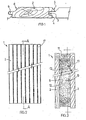
- est une vue en élévation frontale et partiellement coupée d'un élément modulaire pour la constitution de la totalité de la cloison ;
- La figure 3
- est une vue, selon la section par AA, de la figure antérieure ;
- La figure 4
- est une vue en plan de l'élément modulaire répété ;
- La figure 5
- montre dans une vue encore en plan, une variante de réalisation avec un type différent de lames bouvetées ; et
- La figure 6
- correspond à une autre variante d'élément modulaire.
- Figure 1
- is a cross-section or plan detail of one of the bladed blades that make up the exterior walls and internal modules that will form the partition;
- Figure 2
- is a front elevation and partially cut a modular element for the constitution of the entire partition;
- Figure 3
- is a view, according to section by AA, of the previous figure;
- Figure 4
- is a plan view of the repeating modular element;
- Figure 5
- shows in a view still in plan, an alternative embodiment with a different type of knuckle blades; and
- Figure 6
- corresponds to another variant of modular element.
Conformément aux dessins, la cloison préfabriquée autoportante objet de l'invention consiste en une série de modules (1), lesquels, en ayant des dimensions normalisées appropriées aux normes employées dans la construction, pourront rapidement et facilement être situés dans leur emplacement, requérant un minimum d'opérations et de manipulations telles que le sciage et le perçage dans le but de les adapter aux mesures finales.According to the drawings, the self-supporting prefabricated partition according to the invention consists of a series of modules (1), which, having standardized dimensions appropriate to the standards used in the construction, can be quickly and easily located in their location, requiring a minimal operations and manipulations such as sawing and drilling to adapt them to the final measurements.
Chacun de ces modules (1) est formé de deux faces, extérieure et intérieure, constituées de lames verticales bouvetées (2), élaborées de préférence avec du bois de haute qualité, avec un degré d'humidité d'entre 12 et 15% dans le but d'offrir une résistance accentuée à l'action d'agents externes, ainsi que la possibilité de recevoir sur sa surface des produits de finition selon les nécessités décoratives de l'environnement et de l'endroit, tels que des cires, des peintures, des vernis, des laquages ou similaires.Each of these modules (1) is formed of two faces, outer and inner, consisting of vertical planks knuckle (2), preferably made of high quality wood, with a moisture content of between 12 and 15% in the purpose of offering an increased resistance to the action of external agents, as well as the possibility of receiving on its surface finishing products according to the decorative requirements of the environment and the place, such as waxes, paints, varnishes, lacquers or the like.
Chacune de ces lames bouvetées (2) possède sur l'un de ses bords extrêmes un rentrant à section rectangulaire (3), disposé à mode d'entaille longitudinale, présentant une zone plate (4) sur un côté, et une zone plate inclinée (5) croissant vers la propre entaille (3) sur l'autre côté.Each of these tongue-and-groove blades (2) has, on one of its extreme edges, a rectangular section recess (3), arranged in longitudinal slot mode, presenting a flat zone (4) on one side and an inclined flat zone. (5) growing towards the own cut (3) on the other side.
Sur l'autre bord opposé, la lame bouvetée possède un saillant (6) à section rectangulaire et extrémité arrondie, qui présente sur un côté une zone plate horizontale (7) et sur l'autre côté une zone inclinée (8), croissant vers la paroi du saillant (6) et légèrement bornoyée. Les faces latérales de la lame (2) sont plates et parallèles entre elles.On the other opposite edge, the tongue-and-groove blade has a salient (6) with a rectangular cross-section and a rounded end, which on one side has a flat horizontal zone (7) and on the other side an inclined zone (8) extending towards the wall of the salient (6) and slightly bounded. Faces side of the blade (2) are flat and parallel to each other.
Le saillant (6) aura une grosseur identique à la largeur de l'entaille longitudinale (3) dans le but d'être fortement emboîtés et de garantir l'amovibilité des lames (2) déjà situées les unes à la suite des autres.The salient (6) will have a size identical to the width of the longitudinal slot (3) in order to be highly nested and ensure the removability of the blades (2) already located one after the other.
Chacune des lames étant constituée d'accord à ce décrit plus haut et tel qu'il est représenté sur les figures 1 et 4, celles-ci s'uniront les unes aux autres en profitant de leur bouvetage, en introduisant le saillant (6) à l'intérieur de l'entaille (3) de la lame (2) contiguë, et ainsi successivement jusqu'à compléter la totalité du module (1), selon le dimensionnement qui aura été établi.Each of the blades being made according to the above described and as shown in Figures 1 and 4, they will unite to each other taking advantage of their bouvetage, introducing the salient (6) inside the notch (3) of the contiguous blade (2), and thus successively to complete the entire module (1), according to the dimensioning that has been established.
Le module (1) reste complété une fois que l'on a préparé deux ensembles de lames (2) fortement unies entre elles, en les disposant parallèles et en laissant une séparation déjà prédéterminée entre elles, séparation qui sera remplie dans sa totalité avec du polyuréthane injecté, constituant dans ledit intérieur une masse rigide et résistante (9), à faible poids et caractéristiques physico-chimiques aptes pour offrir à l'ensemble une isolation thermique et acoustique, ainsi qu'une résistance au feu par ses caractéristiques ignifuges et d'autoextinction.The module (1) remains completed once two sets of blades (2) have been prepared, strongly united between them, placing them parallel and leaving a separation already predetermined between them, separation which will be filled in its entirety with injected polyurethane, constituting in said interior a rigid and resistant mass (9), low weight and physicochemical characteristics able to offer the whole a thermal and acoustic insulation, as well as a fire resistance by its flame retardant characteristics and 'Self-extinguishing.
Lors du remplissage par injection (9), on disposera sur l'un ou les deux bords extrêmes de chaque panneau, une latte à mode de pilier vertical (10) connue sous le nom technique de tasseau, tandis que sur l'un ou les deux bords extrêmes horizontaux, supérieur et inférieur, on placera de même chacune des baguettes horizontales (11) lesquelles pourront être fixées au tasseau moyennant les classiques aboutements du type queue-d'aronde.During the injection filling (9), there will be disposed on one or both end edges of each panel, a vertical pillar mode slat (10) known under the technical name of cleat, while on one or the two extreme horizontal edges, upper and lower, one will likewise place each of the horizontal rods (11) which can be fixed to the cleat by means of conventional abutments of the type dovetail.
Ce seront généralement six lames (2) que l'on unira pour former chacune des deux faces du module (1). Et en ce qui concerne le dimensionnement desdits modules de leur épaisseur, on présentera de préférence, la grosseur correspondante à une cloison du type mur d'appui, avec une proportion de 40 mm/60 mm/40 mm correspondant à la lame (2), au remplissage (9) de polyuréthane et à une autre lame (2) ; ainsi qu'à une cloison structurelle intérieure ou à une cloison uniquement séparatrice, avec une proportion de 20 mm/40 mm/20 mm chacune d'elles, tout cela avec les variations de dimensionnement des tasseaux et des différentes baguettes qui seront installés sur le panneau ou module (1).It will generally be six blades (2) that will unite to form each of the two faces of the module (1). As regards the dimensioning of said modules of their thickness, the thickness corresponding to a partition of the wall-bearing type, with a proportion of 40 mm / 60 mm / 40 mm corresponding to the blade (2), will preferably be presented. at the filling (9) of polyurethane and at another blade (2); as well as an interior structural partition or a partition only separator, with a proportion of 20 mm / 40 mm / 20 mm each, all this with the variations of sizing batten and the various rods that will be installed on the panel or module (1).
Le module (1) étant constitué, la cloison qui doit être installée demandera le placement et l'union appropriée de plusieurs modules selon la longueur de la cloison en question, recouvrant si nécessaire, la dernière travée de cloison moyennant une portion de module (1) préalablement scié avec l'outil approprié, travail généralement effectué sur les lieux de l'installation. Il peut aussi se réaliser en usine, en réduisant alors le volume de résidus.Since the module (1) is constituted, the partition to be installed will require the placement and appropriate union of several modules according to the length of the partition in question, covering if necessary, the last span of partition by means of a portion of module (1 ) previously sawn with the appropriate tool, work usually performed at the site of the installation. It can also be done in the factory, reducing the volume of residues.
Les particulières qualités des modules (1) qui ont été décrits, se complètent avec la possibilité d'effectuer préalablement, à l'intérieur du remplissage (9) une série d'orifices longitudinaux, autant en sens horizontal (12) qu'en sens vertical (13), orifices à mode de conduits qui contiennent des tubes aptes à la disposition à travers de son intérieur d'un câblage qui sera utilisé pour les multiples applications demandées actuellement, telles que la conduction électrique, l'électronique, celle de transmission de voix et de données, celle de téléphonie, etc., tout ceci demeurant parfaitement occulte et protégé, avec les avantages que cela rapporte.The particular qualities of the modules (1) which have been described, complement each other with the possibility of carrying out beforehand, inside the filling (9) a series of longitudinal orifices, both horizontally (12) and in the direction vertical (13), conduit-type orifices which contain tubes capable of arranging through its interior wiring that will be used for the many applications currently required, such as electrical conduction, electronics, transmission voice and data, telephony, etc., all of which remain perfectly hidden and protected, with the benefits that it brings.
Et en ce qui concerne la qualité d'autoportante, caractéristique essentielle aussi de la cloison que l'on décrit, la présence des antérieurement mentionnés tasseaux, unie aux baguettes horizontales, supérieure et inférieure, disposées sur chaque module (1), donnera a celle-ci la résistance aux déformations tout en supportant des charges, qui la qualifiera d'autoportante.And as regards the quality of self-supporting, also essential feature of the partition that is described, the presence of previously mentioned cleats, together with the horizontal rods, upper and lower, arranged on each module (1), will give that the resistance to deformation while supporting loads, which will qualify as self-supporting.
Comme variantes de réalisation, on doit indiquer la possibilité que les lames convenablement unies qui constitueront les parois du module (1) aient une forme différente, comme représenté sur les figures 5 et 6.As alternative embodiments, the possibility must be given that the suitably united blades which will constitute the walls of the module (1) have a different shape, as shown in FIGS. 5 and 6.
Le bouvetage se trouve réduit à un chevauchement de la languette longitudinale (15), prolongation de la face inférieure de la lame (14), avec la languette longitudinale (16), prolongation de la face supérieure de la lame identique (14) située a continuation, et ainsi de suite.The bouvetage is reduced to an overlap of the longitudinal tongue (15), extension of the underside of the blade (14), with the longitudinal tongue (16), extension of the upper face of the identical blade (14) located next, and so on.
La face intérieure de la lame (14) prolongée par les languettes longitudinales (15), sera totalement plate. La face extérieure de ladite lame (14) restera différenciée dans l'union d'une lame (14) avec sa contiguë, car les arêtes coïncidentes lors du chevauchement présentent un léger chanfreinage (17), y résultant des rentrants angulaires longitudinauxThe inner face of the blade (14) extended by the longitudinal tongues (15), will be completely flat. The outer face of said blade (14) will remain differentiated in the union of a blade (14) with its contiguous, because the edges coinciding at the overlap have a slight chamfering (17), resulting in longitudinal angular reentrants
Les lames (14) et (14a) des figures 5 et 6 ne présentent qu'une différence dimensionnelle en grosseur, étant respectivement applicables sur des cloisons de type simple, de séparation, ou des cloisons de type d'appui, d'une grosseur supérieure.The blades (14) and (14a) of FIGS. 5 and 6 have only a dimensional difference in size, being respectively applicable to partitions of simple type, of separation, or of partitions of type of support, of a size higher.
Évidemment ces cloisons ou murs peuvent êtres employées comme indiqué précédemment, dans la construction sur place de maisons en bois, dans ce cas préfabriquées, puisque lesdites cloisons sont autorésistantes et permettent donc de configurer des murs d'appui, comme prévu pour la pose d'installations électriques et similaires.Obviously these partitions or walls can be used as indicated previously, in the on-site construction of wooden houses, in this case prefabricated, since said partitions are self-supporting and thus allow to configure support walls, as intended for the installation of electrical installations and the like.
Suffisamment décrites les caractéristiques de la cloison préfabriquée autoportante objet de la présente invention, il faut indiquer que toute variation dans les formes, dimensions, aspect extérieur et décor, ainsi comme dans les types de matériaux employés dans la réalisation pratique de la même, n'altèrent en rien l'essentialité de son objet, qui demeure résumé dans les revendication qui suivent.Sufficiently described the characteristics of the self-supporting prefabricated partition object of the present invention, it must be indicated that any variation in the shapes, dimensions, external appearance and decor, as well as in the types of materials used in the practical realization of the same, does not in no way alter the essentiality of its object, which remains summarized in the following claims.
Claims (7)
Applications Claiming Priority (1)
| Application Number | Priority Date | Filing Date | Title |
|---|---|---|---|
| ES200500396U ES1059577Y (en) | 2005-02-22 | 2005-02-22 | SELF-PREFABRICATED PREFABRICATED TABIQUE. |
Publications (2)
| Publication Number | Publication Date |
|---|---|
| EP1700969A2 true EP1700969A2 (en) | 2006-09-13 |
| EP1700969A3 EP1700969A3 (en) | 2009-02-18 |
Family
ID=34566094
Family Applications (1)
| Application Number | Title | Priority Date | Filing Date |
|---|---|---|---|
| EP06380033A Withdrawn EP1700969A3 (en) | 2005-02-22 | 2006-02-14 | Prefabricated self-supporting partition wall |
Country Status (2)
| Country | Link |
|---|---|
| EP (1) | EP1700969A3 (en) |
| ES (1) | ES1059577Y (en) |
Cited By (3)
| Publication number | Priority date | Publication date | Assignee | Title |
|---|---|---|---|---|
| FR2943368A1 (en) * | 2009-03-23 | 2010-09-24 | Rene Gaudin | COMPOSITE INSULATION PANEL WITH WOODEN FACING |
| CN102328336A (en) * | 2011-08-31 | 2012-01-25 | 马克林 | Method for producing bricks and prefabricated parts used for building by utilizing weeds and crop straw |
| BE1024499B1 (en) * | 2017-01-04 | 2018-03-13 | Den Nieuwen Buiten Bvba | A NEW ISOLATED BUILDING ELEMENT WITH CROSS LOCATION OF THE FIBERS AND METHOD FOR USE THEREOF |
Families Citing this family (1)
| Publication number | Priority date | Publication date | Assignee | Title |
|---|---|---|---|---|
| CN110241953B (en) * | 2019-07-19 | 2024-06-07 | 深圳市江天建筑工程有限公司 | Permanently fixed light partition wall slat and construction method |
Citations (1)
| Publication number | Priority date | Publication date | Assignee | Title |
|---|---|---|---|---|
| DE29802083U1 (en) | 1998-02-07 | 1998-04-16 | Bohse Andrea | Wall, ceiling or door element |
Family Cites Families (7)
| Publication number | Priority date | Publication date | Assignee | Title |
|---|---|---|---|---|
| FR1553712A (en) * | 1967-06-21 | 1969-01-17 | ||
| DE3141588A1 (en) * | 1981-07-08 | 1983-01-20 | Erkki 00160 Helsinki Kaire | Building element for constructing a sauna cubicle |
| AT381528B (en) * | 1985-02-15 | 1986-10-27 | Hirsch Hans Sen | BUILDING BOARD PANEL |
| WO1996036777A1 (en) * | 1995-05-16 | 1996-11-21 | Alfred Konnerth | Finished wall element with integral ducts |
| DE29510935U1 (en) * | 1995-07-06 | 1995-09-14 | Fritz, Hubert, 87746 Erkheim | wall |
| DE19905186A1 (en) * | 1999-02-09 | 2000-08-10 | Dennert Kg Veit | Prefabricated interior insulating wall comprizes core plate of mineral insulation plus surface layers covered and bound to outer layers and installation channels within core plate. |
| DE10229984A1 (en) * | 2002-07-03 | 2004-01-15 | Fagerdala Deutschland Gmbh | Panel for building saunas comprises polypropylene foam core with cover layers on either surface |
-
2005
- 2005-02-22 ES ES200500396U patent/ES1059577Y/en not_active Expired - Fee Related
-
2006
- 2006-02-14 EP EP06380033A patent/EP1700969A3/en not_active Withdrawn
Patent Citations (1)
| Publication number | Priority date | Publication date | Assignee | Title |
|---|---|---|---|---|
| DE29802083U1 (en) | 1998-02-07 | 1998-04-16 | Bohse Andrea | Wall, ceiling or door element |
Cited By (6)
| Publication number | Priority date | Publication date | Assignee | Title |
|---|---|---|---|---|
| FR2943368A1 (en) * | 2009-03-23 | 2010-09-24 | Rene Gaudin | COMPOSITE INSULATION PANEL WITH WOODEN FACING |
| EP2239406A1 (en) * | 2009-03-23 | 2010-10-13 | René Gaudin | Insulating composite panel with wooden facings |
| CN102328336A (en) * | 2011-08-31 | 2012-01-25 | 马克林 | Method for producing bricks and prefabricated parts used for building by utilizing weeds and crop straw |
| CN102328336B (en) * | 2011-08-31 | 2014-10-15 | 马克林 | Method for producing bricks and prefabricated parts used for building by utilizing weeds and crop straw |
| BE1024499B1 (en) * | 2017-01-04 | 2018-03-13 | Den Nieuwen Buiten Bvba | A NEW ISOLATED BUILDING ELEMENT WITH CROSS LOCATION OF THE FIBERS AND METHOD FOR USE THEREOF |
| EP3480385A3 (en) * | 2017-01-04 | 2019-10-16 | Den Nieuwen Buiten BVBA | A novel insulated cross-laminated construction element and method for using the same |
Also Published As
| Publication number | Publication date |
|---|---|
| ES1059577U (en) | 2005-05-01 |
| EP1700969A3 (en) | 2009-02-18 |
| ES1059577Y (en) | 2005-12-16 |
Similar Documents
| Publication | Publication Date | Title |
|---|---|---|
| EP3199717B1 (en) | Construction element | |
| CA3052699A1 (en) | Construction system for building a module of a dwelling | |
| EP2220305B1 (en) | Wood panel | |
| EP1700969A2 (en) | Prefabricated self-supporting partition wall | |
| EP1934409A1 (en) | Building system for constructing walls | |
| WO2010086533A1 (en) | Module for a modular construction system, and modular construction consisting of said modules | |
| FR2543592A1 (en) | Modular device for building multi-purpose buried or half-buried premises | |
| EP2377660B1 (en) | Method for manufacturing prefabricated construction panels that combine wood and concrete and panels obtained via said method | |
| FR2556387A1 (en) | Construction element of the type made of expanded polystyrene, intended for building a wall | |
| WO2009027448A1 (en) | Wood prefabricated construction members and construction system | |
| FR3024169A1 (en) | BUILDING ELEMENT | |
| FR3030590A1 (en) | SYSTEM AND METHOD FOR CONSTRUCTING A SPACER WALL | |
| EP3325732B1 (en) | Module for assembling a wall made of paletts and method for creating such a wall | |
| WO2007128906A1 (en) | Quick construction component | |
| EP2678485A1 (en) | Construction with a wooden framework comprising cardboard-based elements and construction module | |
| CA2389783A1 (en) | Panel, profile and modular enclosure equipped therewith | |
| FR2906277A1 (en) | Residential building constructing method, involves fixing wind bracing panels to edge posts and/or edge beams of edge parts of frame for forming continuous wind bracing wall, along facade planes | |
| EP0365512A1 (en) | Prefabricated construction units for building constructions, and construction process of buildings using these building units | |
| FR2958949A1 (en) | Structural component for agglomerated or massive wood bearing wall in e.g. passive building, has concrete blocks and planks formed with same sections integrating insulating core installed in zigzag manner at upper and lower surfaces | |
| EP0127542A1 (en) | Modular thermally insulating building block having a facing, and method of constructing a building | |
| BE1000669A7 (en) | Standard profiled beam - forms mortise joints in all directions | |
| EP2593613B1 (en) | Construction system of a building | |
| FR2898918A1 (en) | Edifice for use as e.g. private home, has floor, walls and roof supported by assembly of stringers and columns which are constituted by ladders, where each ladder comprises posts assembled by horizontal cross bars and diagonal cross bars | |
| WO2004109028A1 (en) | Structural wood elements and system that can be constructed therefrom | |
| FR3022926A1 (en) | STRUCTURING AND / OR INSULATING MODULAR BUILDING SYSTEM FOR BUILDING |
Legal Events
| Date | Code | Title | Description |
|---|---|---|---|
| PUAI | Public reference made under article 153(3) epc to a published international application that has entered the european phase |
Free format text: ORIGINAL CODE: 0009012 |
|
| 17P | Request for examination filed |
Effective date: 20060711 |
|
| AK | Designated contracting states |
Kind code of ref document: A2 Designated state(s): AT BE BG CH CY CZ DE DK EE ES FI FR GB GR HU IE IS IT LI LT LU LV MC NL PL PT RO SE SI SK TR |
|
| AX | Request for extension of the european patent |
Extension state: AL BA HR MK YU |
|
| PUAL | Search report despatched |
Free format text: ORIGINAL CODE: 0009013 |
|
| AK | Designated contracting states |
Kind code of ref document: A3 Designated state(s): AT BE BG CH CY CZ DE DK EE ES FI FR GB GR HU IE IS IT LI LT LU LV MC NL PL PT RO SE SI SK TR |
|
| AX | Request for extension of the european patent |
Extension state: AL BA HR MK YU |
|
| RIC1 | Information provided on ipc code assigned before grant |
Ipc: E04C 2/284 20060101ALI20090109BHEP Ipc: E04C 2/24 20060101ALI20090109BHEP Ipc: E04C 2/38 20060101AFI20060608BHEP |
|
| AKX | Designation fees paid |
Designated state(s): AT BE BG CH CY CZ DE DK EE ES FI FR GB GR HU IE IS IT LI LT LU LV MC NL PL PT RO SE SI SK TR |
|
| STAA | Information on the status of an ep patent application or granted ep patent |
Free format text: STATUS: THE APPLICATION IS DEEMED TO BE WITHDRAWN |
|
| 18D | Application deemed to be withdrawn |
Effective date: 20110901 |