EP1700960B1 - Système d'attache pour éléments sanitaires et réservoirs de chasse - Google Patents
Système d'attache pour éléments sanitaires et réservoirs de chasse Download PDFInfo
- Publication number
- EP1700960B1 EP1700960B1 EP06004705A EP06004705A EP1700960B1 EP 1700960 B1 EP1700960 B1 EP 1700960B1 EP 06004705 A EP06004705 A EP 06004705A EP 06004705 A EP06004705 A EP 06004705A EP 1700960 B1 EP1700960 B1 EP 1700960B1
- Authority
- EP
- European Patent Office
- Prior art keywords
- frame
- mounting system
- mounting
- hollow body
- posts
- Prior art date
- Legal status (The legal status is an assumption and is not a legal conclusion. Google has not performed a legal analysis and makes no representation as to the accuracy of the status listed.)
- Active
Links
- 238000007689 inspection Methods 0.000 claims description 6
- 238000009833 condensation Methods 0.000 claims description 3
- 230000005494 condensation Effects 0.000 claims description 3
- 238000001746 injection moulding Methods 0.000 claims description 3
- XLYOFNOQVPJJNP-UHFFFAOYSA-N water Substances O XLYOFNOQVPJJNP-UHFFFAOYSA-N 0.000 claims 1
- 238000009434 installation Methods 0.000 description 12
- 210000003128 head Anatomy 0.000 description 2
- 239000002184 metal Substances 0.000 description 2
- 101100493712 Caenorhabditis elegans bath-42 gene Proteins 0.000 description 1
- 230000006978 adaptation Effects 0.000 description 1
- 238000004873 anchoring Methods 0.000 description 1
- 238000000071 blow moulding Methods 0.000 description 1
- 238000007664 blowing Methods 0.000 description 1
- 238000006073 displacement reaction Methods 0.000 description 1
- 239000013505 freshwater Substances 0.000 description 1
- 230000002262 irrigation Effects 0.000 description 1
- 238000003973 irrigation Methods 0.000 description 1
- 238000004519 manufacturing process Methods 0.000 description 1
- 230000007246 mechanism Effects 0.000 description 1
- 238000000034 method Methods 0.000 description 1
- 210000001331 nose Anatomy 0.000 description 1
- 210000004197 pelvis Anatomy 0.000 description 1
- 238000009428 plumbing Methods 0.000 description 1
- 238000010079 rubber tapping Methods 0.000 description 1
- 239000000725 suspension Substances 0.000 description 1
Images


Classifications
-
- E—FIXED CONSTRUCTIONS
- E03—WATER SUPPLY; SEWERAGE
- E03D—WATER-CLOSETS OR URINALS WITH FLUSHING DEVICES; FLUSHING VALVES THEREFOR
- E03D1/00—Water flushing devices with cisterns ; Setting up a range of flushing devices or water-closets; Combinations of several flushing devices
- E03D1/01—Shape or selection of material for flushing cisterns
- E03D1/012—Details of shape of cisterns, e.g. for connecting to wall, for supporting or connecting flushing-device actuators
-
- E—FIXED CONSTRUCTIONS
- E03—WATER SUPPLY; SEWERAGE
- E03D—WATER-CLOSETS OR URINALS WITH FLUSHING DEVICES; FLUSHING VALVES THEREFOR
- E03D11/00—Other component parts of water-closets, e.g. noise-reducing means in the flushing system, flushing pipes mounted in the bowl, seals for the bowl outlet, devices preventing overflow of the bowl contents; devices forming a water seal in the bowl after flushing, devices eliminating obstructions in the bowl outlet or preventing backflow of water and excrements from the waterpipe
- E03D11/13—Parts or details of bowls; Special adaptations of pipe joints or couplings for use with bowls, e.g. provisions in bowl construction preventing backflow of waste-water from the bowl in the flushing pipe or cistern, provisions for a secondary flushing, for noise-reducing
- E03D11/14—Means for connecting the bowl to the wall, e.g. to a wall outlet
- E03D11/143—Mounting frames for toilets and urinals
- E03D11/146—Mounting frames for toilets and urinals with incorporated cistern
Definitions
- the present invention relates to a fastening system for sanitary elements, comprising a frame which is supported on at least one post on the bottom and fastening means for a cistern, which is received between two posts, wherein the frame is suitable for corner mounting and holding means on the frame for a Wall mounting are provided.
- a generic mounting system for the front wall mounting is known in which a mounting frame on vertical side panels has mounting bracket so that the mounting frame can be mounted on walls of a 90 ° building corner.
- sanitary elements can be set, which are also suitable for installation in a building corner.
- the disadvantage of this fastening system is that this can only be rigidly mounted in a 90 ° building corner, but there may be angle deviations that can not be compensated.
- the cistern for corner mounting is elaborately made, usually in blow molding.
- a connector for the attachment of mounting profiles of plumbing which has two hingedly interconnected connecting straps, each having means for their attachment to a mounting profile or a building wall.
- From corresponding connectors and hollow profile bars can form a support frame, which can be mounted in particular in a room corner.
- it is necessary to adjust all the connectors with a relatively large number of connectors being required to produce a support frame. The time required for the mounting of the support frame and the adjustment of the connector is unsatisfactory.
- a mounting frame for sanitary apparatus which has a mounting frame having feet to be parked at a lower end on a building floor and adjustable at an upper end side supports for its attachment to a building wall.
- Beplankungsschienen are mounted, which preferably extend parallel to vertical struts of the mounting frame.
- Swiveling wall brackets are also mounted on the side supports.
- the mounting frame can be mounted in a room corner, wherein the mounting frame can also be aligned so that the attached sanitary element protrudes at an angle deviating from 45 ° from the building corner forming walls.
- the mounting and alignment of this mounting frame requires a relatively long time.
- a toilet installation unit which consists of a molded part, in which supply and / or disposal lines, control valves and a cistern are integrated.
- the hollow body of the cistern is closed by a separately manufactured hood which has a surrounding of a mounting frame inspection opening.
- the suspension or exhibition of the molded part by means of molded slots through which the installation unit can be pushed onto the protruding arms of a mounting bracket to be attached to an on-site wall mounting bracket.
- the substantially flat front wall and rear wall of the installation unit are extended to lateral stiffening or mounting flanges, which are substantially congruent and rectangular in shape.
- the stiffening or mounting flanges thus define relatively wide and deep Vermörtelungsnuten, in which also sheet metal profiles are used, which are used in installation of the installation unit in lightweight walls for anchoring tapping screws and can be extended by free-standing installation unit by footrests.
- Object of the present invention is to provide a fastening system of the type mentioned, which is simple and can be flexibly mounted in building corners.
- the fastening system for sanitary elements comprises a frame on which protrudes at least one curved web on the back, are guided displaceably on the holding means, so that the frame in different angular positions relative to the walls of a building corner can be mounted.
- the frame does not have to be rigidly mounted in a 90 ° building corner, but it can be made an individual adjustment, so that the sanitary elements can protrude at different angles in the room.
- angle differences can be compensated at building corners, as they are not always present at 90 ° angle.
- the holding means can be hung on the web and have protruding tabs for fixing the frame on walls of a building. This can be done by a displacement of the holding means the position of the frame relative to the building corner can be varied. When the desired position is reached, the retaining means can be fixed to the building wall so that the frame is also fixed in position.
- the frame is equipped with two back holding means or back profiles, so that a back panel with a suitable plate is possible. This plate is required whenever the fastening system is not placed in a corner of a room, but installed in a corner formed by the side wall of a bathtub and a transverse wall.
- the posts of the frame are designed for a height adjustment telescopic. Because the mounting height can thus be easily adapted for the particular application.
- Another way of adjusting the height can be achieved that are provided between the post webs for fastening means for the installation of basins and the fasteners in different Heights are mountable. For example, may be provided at the webs a plurality of spaced-apart in height openings at which then the threaded bolts for the installation of the pelvis can be introduced.
- a cistern with a hollow body is provided between the uprights of the frame, on the front side an inspection opening is formed, which is surrounded by a mounting frame, which is produced integrally with the hollow body by injection molding, wherein the hollow body is closed by a separately formed lid.
- a mounting frame which is produced integrally with the hollow body by injection molding, wherein the hollow body is closed by a separately formed lid.
- the lid can be locked on the hollow body.
- locking lugs can be molded onto the hollow body, which can be brought into engagement with corresponding latching elements on the cover.
- the Spülkasten redesign can be placed by means of a deferred from below bracket positively on the hollow body.
- the hollow body of the cistern has a suitable for installation in building corners contour and, for example, in plan view be substantially triangular.
- the contour can be dimensioned so that adjacent to the cistern still irrigation lines can be placed to supply the cistern with fresh water.
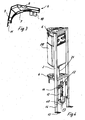
- An attachment system 1 for sanitary elements comprises a support frame, which has two vertical posts 2, which are connected to one another via a lower transverse strut 3 and an upper cross strut 4.
- the posts 2 and cross struts 3 and 4 are made of metal and can be welded together.
- On the back of the support frame two curved webs 5 are arranged at different heights, which have the shape of a semicircle.
- At the webs 5 holding means 6 are fixed, which consist of plastic and are guided there displaceable. Beneath the lower transverse strut 3, webs 12 and a lower end strip 13 are mounted between the posts 2.
- the holding means 6 comprises a curved inner surface 7 which can be applied to the web 5, wherein corresponding guide means to be present on the web 5 or the holding means 6 for a determination can.
- Distanced from the curved bar 7 straight webs 8 and 9 are provided, which are arranged at an angle of approximately 90 ° to each other. These straight webs 8 and 9 can be applied to walls of a building corner. From the webs 8 and 9 are down tabs 10 and 11 show that can be fixed to a building wall via fasteners, such as screws.
- 2 profiles 14 are inserted into the bottom side of the post, which can be telescopically clamped in the post 2, so that the posts 2 are adjustable in height.
- Bodenmann 14 plates 15 are provided on the profiles, which can be screwed to a floor.
- a cistern 20 can be mounted in the upper area, which has laterally protruding tabs 23, which are screwed to the posts 2.
- the cistern 20 is followed by a drain pipe 21, which is formed bent and with an opening 22 to a basin, such as a toilet bowl, urinal can be connected.
- 12 openings 16 are recessed on the webs, can be inserted into the corresponding bolts to set a basin on the frame. Since a plurality of openings 16 are provided on the webs 12, the basin can be mounted at different heights on the webs 12. Thus, by the choice of the mounting opening 16 is a height adjustment.
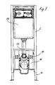
- FIG. 4 shows, in the lower region of the frame 2, 3, 4, 14, a free space 40 is provided which is necessary in so-called finished floors, so that a drainage line can be warped on it in a suitcase.
- the SpülkastenMap is shaped so that a condensation protection sits by means of a pushed-down from the holder 41 positively on the hollow body.
- the cistern 20 is shown in detail.
- the cistern consisting of plastic comprises a hollow body 30, on whose front side an inspection opening 39 is formed.
- the inspection opening 39 is surrounded by a frame 33 which serves to define an actuating plate.
- the hollow body 30 is provided at the lower end with a discharge nozzle 32 which can be closed by attachable in the cistern 20 mechanisms. Laterally on the hollow body 30 protruding tabs 23 are formed to be fixed to the frame.
- the hollow body 30 with the frame 33 and the outlet pipe 32 is integrally made by injection molding.
- a lid 31 is provided in the upper region, which has a substantially triangular contour and can be latched onto the hollow body 30.
- the cistern 20 can be manufactured and installed in the simplest way.
- the connection between the cover 31 and the hollow body 30 is shown in detail in FIG FIG. 8 shown.
- the lid 31 includes a downwardly extending edge 37, on the inside protruding locking lugs 38 are formed.
- the hollow body 30, however, comprises a vertically upwardly projecting edge 34, which is provided with recesses 35, arranged above the thickened latching elements 36 are.
- the lid 31 is merely snapped onto the hollow body 30, wherein the elastic edge 37 jumps outwards until the latching noses 38 rest in the recesses 35. After the degree of filling of the cistern 20 does not rise to the lid 31, no leakage problems can arise in this area.
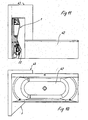
- FIGS. 9 to 12 show the installation of the fastening system 1 in combination with a bathtub 42. Thereafter, the fastening system 1 is placed laterally at the head or at the foot of a bathtub 42. In the execution of the FIG. 9 the fastening system 1 is in a formed from the side wall of the bath 42 and a transverse wall 43 thereto.
- the FIG. 10 shows the arrangement in a plan view. Thereafter, the end portion of the bathtub 42 is installed in the corner of a wall member 43. The fastening system 1 is then installed in the side wall formed by the room interior and a corner formed transversely thereto.
- the FIG. 11 shows this arrangement in a side view.
- the FIG. 12 shows that the angular wall member 43 in turn surrounds the end portion of a bathtub 42, but that the fastener 1 is laterally next to a side wall of the bathtub or at the head or foot end mutatis mutandis free in the room.
Landscapes
- Health & Medical Sciences (AREA)
- Life Sciences & Earth Sciences (AREA)
- Engineering & Computer Science (AREA)
- Hydrology & Water Resources (AREA)
- Public Health (AREA)
- Water Supply & Treatment (AREA)
- Residential Or Office Buildings (AREA)
- Sanitary Device For Flush Toilet (AREA)
- External Artificial Organs (AREA)
- Absorbent Articles And Supports Therefor (AREA)
- Orthopedics, Nursing, And Contraception (AREA)
Claims (13)
- Système de fixation pour éléments sanitaires, avec un bâti (2, 3, 4, 14), qui prend appui sur le sol avec au moins d'un montant (2, 14) et présente des moyens de fixation pour un réservoir de chasse d'eau (20), qui est logé entre deux montants (2, 14), le bâti (2, 3, 4, 14) étant apte au montage dans un coin et des moyens de maintien (6, 10, 11, 10' 11') étant prévus sur le bâti (2, 3, 4, 14) pour un montage mural, caractérisé en ce que, sur le bâti (2, 3, 4, 14), fait saillie, sur la face arrière, au moins une âme courbe (5), sur laquelle les moyens de maintien (6) peuvent être déplacés, de sorte que le bâti (2, 3, 4, 14) puisse être monté dans des positions angulaires différentes par rapport aux murs d'un coin d'un bâtiment.
- Système de fixation selon la revendication 1, caractérisé en ce que les moyens de maintien (6) peuvent être accrochés à l'âme (5) et présentent des attaches en saillie (10, 11) pour la fixation du bâti (2, 3, 4, 14) à des murs d'un bâtiment.
- Système de fixation selon revendication 1 ou 2, caractérisé en ce que les montants (2, 14) du bâti sont conçus pour permettre un ajustage de manière télescopique.
- Système de fixation selon l'une des revendications 1 à 3, caractérisé en ce que des pattes (12) sont prévues, entre les montants (2), pour des moyens de fixation, destinés au montage de cuvettes, et que les moyens de fixation peuvent être montés à des hauteurs différentes.
- Système de fixation selon l'une des revendications 1 à 4, caractérisé en ce que le bâti (2, 3, 4, 14) présente, dans la section inférieure, un espace libre (40), destiné à recevoir un logement pour une conduite d'évacuation d'eau.
- Système de fixation selon l'une des revendications 1 à 5, caractérisé en ce que, dans la section inferieure du bâti (2, 3, 4, 14), est prévue une traverse (13), qui est conçue de sorte qu'un coude d'évacuation puisse être monté de l'avant.
- Système de fixation selon l'une des revendications 1 à 6, caractérisé en ce que le bâti (2, 3, 4, 14) est équipé, à l'arrière, de deux moyens de maintien (6), de sorte que le système de fixation puisse être revêtu d'une plaque, sur la face arrière.
- Système de fixation selon l'une des revendications 1 à 7, caractérisé en ce que, entre les montants (2, 14), est prévu un réservoir de chasse (20) avec un corps creux (30), sur la face avant duquel est pratiquée une ouverture de contrôle (39), qui est entourée par un cadre de montage (33), qui est fabriqué d'une pièce avec le corps creux (30) selon le procédé de moulage par injection, le corps creux (30) étant fermé au moyen d'un couvercle (31), qui est formé séparément.
- Système de fixation selon la revendication 8, caractérisé en ce que le couvercle (31) peut être encliqueté sur le corps creux (30).
- Système de fixation selon la revendication 9, caractérisé en ce que, sur le corps creux (30), sont formés par injection des nez d'arrêt (36) qui peuvent entrer en prise avec des éléments d'arrêt (38) correspondants, prévus sur le couvercle (31).
- Système de fixation selon l'une des revendications 8 à 10, caractérisé en ce que le corps creux (30), vu d'en haut, est de forme sensiblement triangulaire.
- Système de fixation selon l'une des revendications 8 à 11, caractérisé en ce que des attaches (23), en saillie latérale, sont formées sur le corps creux (30), pour la fixation au bâti (2, 3, 4, 14).
- Système de fixation selon l'une des revendications 8 à 12, caractérisé en ce que le corps du réservoir de chasse est formé de sorte qu'un dispositif de protection contre le suintement d'eau puisse être emboîté sur le corps creux, au moyen d'un support (41), qui peut être enfilé par le bas.
Applications Claiming Priority (2)
| Application Number | Priority Date | Filing Date | Title |
|---|---|---|---|
| DE202005003864 | 2005-03-08 | ||
| DE202005016946U DE202005016946U1 (de) | 2005-03-08 | 2005-10-27 | Befestigungssystem für Sanitärelemente und Spülkasten |
Publications (3)
| Publication Number | Publication Date |
|---|---|
| EP1700960A2 EP1700960A2 (fr) | 2006-09-13 |
| EP1700960A3 EP1700960A3 (fr) | 2008-08-27 |
| EP1700960B1 true EP1700960B1 (fr) | 2010-06-09 |
Family
ID=35669072
Family Applications (1)
| Application Number | Title | Priority Date | Filing Date |
|---|---|---|---|
| EP06004705A Active EP1700960B1 (fr) | 2005-03-08 | 2006-03-08 | Système d'attache pour éléments sanitaires et réservoirs de chasse |
Country Status (4)
| Country | Link |
|---|---|
| EP (1) | EP1700960B1 (fr) |
| AT (1) | ATE470763T1 (fr) |
| DE (2) | DE202005016946U1 (fr) |
| ES (1) | ES2344797T3 (fr) |
Families Citing this family (5)
| Publication number | Priority date | Publication date | Assignee | Title |
|---|---|---|---|---|
| DE202006016840U1 (de) * | 2006-10-31 | 2008-03-06 | Comfort Sinusverteiler Gmbh | Kaskadeneinheit für eine Heizungsanlage |
| NL2004067C2 (nl) * | 2010-01-06 | 2011-07-07 | Easy Sanitary Solutions B V | Inbouwreservoir. |
| ES2605202B1 (es) * | 2015-09-10 | 2017-10-04 | Juan Pedro Burgos Castillo | Cisterna monobloque |
| CN214657490U (zh) * | 2021-01-20 | 2021-11-09 | 厦门融技精密科技有限公司 | 一种能够加长调节范围的固定机构 |
| DE202021106653U1 (de) | 2021-12-07 | 2023-03-08 | Viega Technology Gmbh & Co. Kg | Halterung für einen Vorwand-Montagerahmen sowie Befestigungssystem mit einer solchen Halterung und einem Vorwand-Montagerahmen |
Family Cites Families (9)
| Publication number | Priority date | Publication date | Assignee | Title |
|---|---|---|---|---|
| US2652875A (en) * | 1951-02-26 | 1953-09-22 | Puste Elizabeth | Cover for toilet tanks |
| US3760428A (en) * | 1971-10-29 | 1973-09-25 | Borg Warner | Water closet tank |
| DE3517907A1 (de) * | 1985-05-17 | 1986-11-20 | Sanbloc GmbH Installations-Fertigbau, 8120 Weilheim | Wc-installationseinheit |
| AU673292B2 (en) * | 1993-11-10 | 1996-10-31 | Caroma Industries Limited | A cistern |
| DE19636298C1 (de) * | 1996-09-06 | 1997-12-18 | Rost & Co Gmbh | Spülkasten |
| DE29621470U1 (de) * | 1996-12-11 | 1997-06-12 | Rohmann, Klaus, 44357 Dortmund | Spülkasten für ein Wasserklosett, ein Urinal o.dgl. |
| DE29803394U1 (de) | 1998-02-26 | 1998-05-14 | E. Missel GmbH & Co., 70374 Stuttgart | Spülsystem |
| EP1371788B1 (fr) * | 2002-06-10 | 2007-10-03 | Geberit Technik Ag | Support pour le montage d' appareils sanitaires |
| DE20300469U1 (de) * | 2003-01-14 | 2003-06-12 | Geberit Technik AG, Jona, St. Gallen | Verbinder für die Befestigung von Montageprofilen der Sanitärtechnik sowie Traggestell mit einem solchen Verbinder |
-
2005
- 2005-10-27 DE DE202005016946U patent/DE202005016946U1/de not_active Expired - Lifetime
-
2006
- 2006-03-08 AT AT06004705T patent/ATE470763T1/de active
- 2006-03-08 EP EP06004705A patent/EP1700960B1/fr active Active
- 2006-03-08 DE DE502006007136T patent/DE502006007136D1/de active Active
- 2006-03-08 ES ES06004705T patent/ES2344797T3/es active Active
Also Published As
| Publication number | Publication date |
|---|---|
| DE502006007136D1 (de) | 2010-07-22 |
| ES2344797T3 (es) | 2010-09-07 |
| DE202005016946U1 (de) | 2006-01-12 |
| ATE470763T1 (de) | 2010-06-15 |
| EP1700960A2 (fr) | 2006-09-13 |
| EP1700960A3 (fr) | 2008-08-27 |
Similar Documents
| Publication | Publication Date | Title |
|---|---|---|
| EP2236683B1 (fr) | Agencement de rainures de douche pour montage mural | |
| EP2333174B1 (fr) | Système d'écoulement de douche | |
| EP1700960B1 (fr) | Système d'attache pour éléments sanitaires et réservoirs de chasse | |
| EP0939170B1 (fr) | Système de chasse d'eau | |
| DE2902967A1 (de) | Wandelement mit verrohrung fuer nassraum, sanitaerraum, kueche o.dgl. | |
| EP0044055B1 (fr) | Cellule sanitaire construite au moyen d'éléments préfabriqués | |
| DE19710647A1 (de) | Waschbeckeninstallation | |
| EP0731223B1 (fr) | Dispositif de montage pour le support d'un aménagement sanitaire | |
| AT14857U1 (de) | Einrichtung für die Körperpflege | |
| EP0731226B1 (fr) | Elément pour l'assemblage d'une installation sanitaire devant une paroi | |
| EP0324169B1 (fr) | Bloc d'installation | |
| EP2690229B1 (fr) | Dispositif de montage pour un appareil sanitaire | |
| EP0662546A2 (fr) | Bloc de construction, pour la fixation d'installations et/ou appareils sanitaires sur une paroi | |
| DE202015001752U1 (de) | Spüleinheit | |
| DE29806398U1 (de) | Spülsystem | |
| EP0790359B1 (fr) | Dispositif de fixation pour article sanitaire | |
| DE10207067A1 (de) | Bausatz zur Erzeugung insbesondere einer Vorwand-Eckinstallation für ein WC oder dgl. | |
| EP0520269B1 (fr) | Bloc d'installation | |
| DE19736341C2 (de) | Befestigungsvorrichtung | |
| EP0482506A1 (fr) | Système d'installation | |
| DE29803396U1 (de) | Montagerahmen zur Positionierung und schallentkoppelten Befestigung eines Behältnisses zur Zwischenspeicherung einer vorgebbaren Wassermenge | |
| DE202021106653U1 (de) | Halterung für einen Vorwand-Montagerahmen sowie Befestigungssystem mit einer solchen Halterung und einem Vorwand-Montagerahmen | |
| EP1367187A2 (fr) | Kit pour élément sanitaire de chasse d'eau | |
| DE19756149A1 (de) | Unterputz-Eckspülkasten für Wand-WC mit und ohne Träger oder als Block bzw. Baustein | |
| EP1676511A1 (fr) | Installation de douche |
Legal Events
| Date | Code | Title | Description |
|---|---|---|---|
| PUAI | Public reference made under article 153(3) epc to a published international application that has entered the european phase |
Free format text: ORIGINAL CODE: 0009012 |
|
| AK | Designated contracting states |
Kind code of ref document: A2 Designated state(s): AT BE BG CH CY CZ DE DK EE ES FI FR GB GR HU IE IS IT LI LT LU LV MC NL PL PT RO SE SI SK TR |
|
| AX | Request for extension of the european patent |
Extension state: AL BA HR MK YU |
|
| PUAL | Search report despatched |
Free format text: ORIGINAL CODE: 0009013 |
|
| AK | Designated contracting states |
Kind code of ref document: A3 Designated state(s): AT BE BG CH CY CZ DE DK EE ES FI FR GB GR HU IE IS IT LI LT LU LV MC NL PL PT RO SE SI SK TR |
|
| AX | Request for extension of the european patent |
Extension state: AL BA HR MK YU |
|
| 17P | Request for examination filed |
Effective date: 20090122 |
|
| 17Q | First examination report despatched |
Effective date: 20090227 |
|
| AKX | Designation fees paid |
Designated state(s): AT BE BG CH CY CZ DE DK EE ES FI FR GB GR HU IE IS IT LI LT LU LV MC NL PL PT RO SE SI SK TR |
|
| GRAP | Despatch of communication of intention to grant a patent |
Free format text: ORIGINAL CODE: EPIDOSNIGR1 |
|
| GRAS | Grant fee paid |
Free format text: ORIGINAL CODE: EPIDOSNIGR3 |
|
| GRAA | (expected) grant |
Free format text: ORIGINAL CODE: 0009210 |
|
| AK | Designated contracting states |
Kind code of ref document: B1 Designated state(s): AT BE BG CH CY CZ DE DK EE ES FI FR GB GR HU IE IS IT LI LT LU LV MC NL PL PT RO SE SI SK TR |
|
| REG | Reference to a national code |
Ref country code: CH Ref legal event code: EP |
|
| REG | Reference to a national code |
Ref country code: CH Ref legal event code: NV Representative=s name: TROESCH SCHEIDEGGER WERNER AG |
|
| REG | Reference to a national code |
Ref country code: IE Ref legal event code: FG4D Free format text: LANGUAGE OF EP DOCUMENT: GERMAN |
|
| REF | Corresponds to: |
Ref document number: 502006007136 Country of ref document: DE Date of ref document: 20100722 Kind code of ref document: P |
|
| REG | Reference to a national code |
Ref country code: NL Ref legal event code: T3 |
|
| REG | Reference to a national code |
Ref country code: ES Ref legal event code: FG2A Ref document number: 2344797 Country of ref document: ES Kind code of ref document: T3 |
|
| PG25 | Lapsed in a contracting state [announced via postgrant information from national office to epo] |
Ref country code: SE Free format text: LAPSE BECAUSE OF FAILURE TO SUBMIT A TRANSLATION OF THE DESCRIPTION OR TO PAY THE FEE WITHIN THE PRESCRIBED TIME-LIMIT Effective date: 20100609 Ref country code: LT Free format text: LAPSE BECAUSE OF FAILURE TO SUBMIT A TRANSLATION OF THE DESCRIPTION OR TO PAY THE FEE WITHIN THE PRESCRIBED TIME-LIMIT Effective date: 20100609 |
|
| LTIE | Lt: invalidation of european patent or patent extension |
Effective date: 20100609 |
|
| PG25 | Lapsed in a contracting state [announced via postgrant information from national office to epo] |
Ref country code: SI Free format text: LAPSE BECAUSE OF FAILURE TO SUBMIT A TRANSLATION OF THE DESCRIPTION OR TO PAY THE FEE WITHIN THE PRESCRIBED TIME-LIMIT Effective date: 20100609 Ref country code: LV Free format text: LAPSE BECAUSE OF FAILURE TO SUBMIT A TRANSLATION OF THE DESCRIPTION OR TO PAY THE FEE WITHIN THE PRESCRIBED TIME-LIMIT Effective date: 20100609 Ref country code: FI Free format text: LAPSE BECAUSE OF FAILURE TO SUBMIT A TRANSLATION OF THE DESCRIPTION OR TO PAY THE FEE WITHIN THE PRESCRIBED TIME-LIMIT Effective date: 20100609 |
|
| PG25 | Lapsed in a contracting state [announced via postgrant information from national office to epo] |
Ref country code: PL Free format text: LAPSE BECAUSE OF FAILURE TO SUBMIT A TRANSLATION OF THE DESCRIPTION OR TO PAY THE FEE WITHIN THE PRESCRIBED TIME-LIMIT Effective date: 20100609 Ref country code: GR Free format text: LAPSE BECAUSE OF FAILURE TO SUBMIT A TRANSLATION OF THE DESCRIPTION OR TO PAY THE FEE WITHIN THE PRESCRIBED TIME-LIMIT Effective date: 20100910 Ref country code: CY Free format text: LAPSE BECAUSE OF FAILURE TO SUBMIT A TRANSLATION OF THE DESCRIPTION OR TO PAY THE FEE WITHIN THE PRESCRIBED TIME-LIMIT Effective date: 20100609 |
|
| REG | Reference to a national code |
Ref country code: IE Ref legal event code: FD4D |
|
| PG25 | Lapsed in a contracting state [announced via postgrant information from national office to epo] |
Ref country code: IE Free format text: LAPSE BECAUSE OF FAILURE TO SUBMIT A TRANSLATION OF THE DESCRIPTION OR TO PAY THE FEE WITHIN THE PRESCRIBED TIME-LIMIT Effective date: 20100609 Ref country code: EE Free format text: LAPSE BECAUSE OF FAILURE TO SUBMIT A TRANSLATION OF THE DESCRIPTION OR TO PAY THE FEE WITHIN THE PRESCRIBED TIME-LIMIT Effective date: 20100609 |
|
| PG25 | Lapsed in a contracting state [announced via postgrant information from national office to epo] |
Ref country code: SK Free format text: LAPSE BECAUSE OF FAILURE TO SUBMIT A TRANSLATION OF THE DESCRIPTION OR TO PAY THE FEE WITHIN THE PRESCRIBED TIME-LIMIT Effective date: 20100609 Ref country code: IS Free format text: LAPSE BECAUSE OF FAILURE TO SUBMIT A TRANSLATION OF THE DESCRIPTION OR TO PAY THE FEE WITHIN THE PRESCRIBED TIME-LIMIT Effective date: 20101009 Ref country code: RO Free format text: LAPSE BECAUSE OF FAILURE TO SUBMIT A TRANSLATION OF THE DESCRIPTION OR TO PAY THE FEE WITHIN THE PRESCRIBED TIME-LIMIT Effective date: 20100609 Ref country code: PT Free format text: LAPSE BECAUSE OF FAILURE TO SUBMIT A TRANSLATION OF THE DESCRIPTION OR TO PAY THE FEE WITHIN THE PRESCRIBED TIME-LIMIT Effective date: 20101011 |
|
| PLBE | No opposition filed within time limit |
Free format text: ORIGINAL CODE: 0009261 |
|
| STAA | Information on the status of an ep patent application or granted ep patent |
Free format text: STATUS: NO OPPOSITION FILED WITHIN TIME LIMIT |
|
| PG25 | Lapsed in a contracting state [announced via postgrant information from national office to epo] |
Ref country code: DK Free format text: LAPSE BECAUSE OF FAILURE TO SUBMIT A TRANSLATION OF THE DESCRIPTION OR TO PAY THE FEE WITHIN THE PRESCRIBED TIME-LIMIT Effective date: 20100609 |
|
| 26N | No opposition filed |
Effective date: 20110310 |
|
| REG | Reference to a national code |
Ref country code: DE Ref legal event code: R097 Ref document number: 502006007136 Country of ref document: DE Effective date: 20110309 |
|
| PG25 | Lapsed in a contracting state [announced via postgrant information from national office to epo] |
Ref country code: MC Free format text: LAPSE BECAUSE OF NON-PAYMENT OF DUE FEES Effective date: 20110331 |
|
| REG | Reference to a national code |
Ref country code: DE Ref legal event code: R083 Ref document number: 502006007136 Country of ref document: DE |
|
| PG25 | Lapsed in a contracting state [announced via postgrant information from national office to epo] |
Ref country code: TR Free format text: LAPSE BECAUSE OF FAILURE TO SUBMIT A TRANSLATION OF THE DESCRIPTION OR TO PAY THE FEE WITHIN THE PRESCRIBED TIME-LIMIT Effective date: 20100609 Ref country code: BG Free format text: LAPSE BECAUSE OF FAILURE TO SUBMIT A TRANSLATION OF THE DESCRIPTION OR TO PAY THE FEE WITHIN THE PRESCRIBED TIME-LIMIT Effective date: 20100909 |
|
| PG25 | Lapsed in a contracting state [announced via postgrant information from national office to epo] |
Ref country code: HU Free format text: LAPSE BECAUSE OF FAILURE TO SUBMIT A TRANSLATION OF THE DESCRIPTION OR TO PAY THE FEE WITHIN THE PRESCRIBED TIME-LIMIT Effective date: 20100609 |
|
| REG | Reference to a national code |
Ref country code: FR Ref legal event code: PLFP Year of fee payment: 11 |
|
| PG25 | Lapsed in a contracting state [announced via postgrant information from national office to epo] |
Ref country code: IT Free format text: LAPSE BECAUSE OF NON-PAYMENT OF DUE FEES Effective date: 20160308 |
|
| REG | Reference to a national code |
Ref country code: FR Ref legal event code: PLFP Year of fee payment: 12 |
|
| REG | Reference to a national code |
Ref country code: DE Ref legal event code: R082 Ref document number: 502006007136 Country of ref document: DE Representative=s name: COHAUSZ & FLORACK PATENT- UND RECHTSANWAELTE P, DE Ref country code: DE Ref legal event code: R081 Ref document number: 502006007136 Country of ref document: DE Owner name: VIEGA TECHNOLOGY GMBH & CO. KG, DE Free format text: FORMER OWNER: VIEGA GMBH & CO. KG, 57439 ATTENDORN, DE |
|
| REG | Reference to a national code |
Ref country code: AT Ref legal event code: PC Ref document number: 470763 Country of ref document: AT Kind code of ref document: T Owner name: VIEGA TECHNOLOGY GMBH & CO. KG, DE Effective date: 20170512 |
|
| REG | Reference to a national code |
Ref country code: LU Ref legal event code: PD Owner name: VIEGA TECHNOLOGY GMBH & CO. KG; DE Free format text: FORMER OWNER: VIEGA GMBH & CO. KG Effective date: 20170322 |
|
| REG | Reference to a national code |
Ref country code: NL Ref legal event code: PD Owner name: VIEGA TECHNOLOGY GMBH & CO. KG; DE Free format text: DETAILS ASSIGNMENT: CHANGE OF OWNER(S), ASSIGNMENT; FORMER OWNER NAME: VIEGA GMBH & CO. KG Effective date: 20170412 |
|
| REG | Reference to a national code |
Ref country code: GB Ref legal event code: 732E Free format text: REGISTERED BETWEEN 20170706 AND 20170715 |
|
| PG25 | Lapsed in a contracting state [announced via postgrant information from national office to epo] |
Ref country code: IT Free format text: LAPSE BECAUSE OF NON-PAYMENT OF DUE FEES Effective date: 20160308 |
|
| PGRI | Patent reinstated in contracting state [announced from national office to epo] |
Ref country code: IT Effective date: 20170710 |
|
| REG | Reference to a national code |
Ref country code: FR Ref legal event code: TP Owner name: VIEGA TECHNOLOGY GMBH & CO. KG, DE Effective date: 20171013 |
|
| REG | Reference to a national code |
Ref country code: ES Ref legal event code: PC2A Owner name: VIEGA TECHNOLOGY GMBH & CO. KG Effective date: 20180108 |
|
| REG | Reference to a national code |
Ref country code: CH Ref legal event code: PUE Owner name: VIEGA TECHNOLOGY GMBH AND CO. KG, DE Free format text: FORMER OWNER: VIEGA GMBH AND CO. KG, DE |
|
| REG | Reference to a national code |
Ref country code: FR Ref legal event code: PLFP Year of fee payment: 13 |
|
| PGFP | Annual fee paid to national office [announced via postgrant information from national office to epo] |
Ref country code: LU Payment date: 20210318 Year of fee payment: 16 |
|
| PGFP | Annual fee paid to national office [announced via postgrant information from national office to epo] |
Ref country code: AT Payment date: 20220322 Year of fee payment: 17 |
|
| PGFP | Annual fee paid to national office [announced via postgrant information from national office to epo] |
Ref country code: NL Payment date: 20220323 Year of fee payment: 17 Ref country code: CZ Payment date: 20220217 Year of fee payment: 17 Ref country code: BE Payment date: 20220323 Year of fee payment: 17 |
|
| PGFP | Annual fee paid to national office [announced via postgrant information from national office to epo] |
Ref country code: IT Payment date: 20220324 Year of fee payment: 17 Ref country code: ES Payment date: 20220420 Year of fee payment: 17 |
|
| PG25 | Lapsed in a contracting state [announced via postgrant information from national office to epo] |
Ref country code: LU Free format text: LAPSE BECAUSE OF NON-PAYMENT OF DUE FEES Effective date: 20220308 |
|
| PGFP | Annual fee paid to national office [announced via postgrant information from national office to epo] |
Ref country code: FR Payment date: 20230323 Year of fee payment: 18 |
|
| PGFP | Annual fee paid to national office [announced via postgrant information from national office to epo] |
Ref country code: GB Payment date: 20230322 Year of fee payment: 18 |
|
| PGFP | Annual fee paid to national office [announced via postgrant information from national office to epo] |
Ref country code: CH Payment date: 20230401 Year of fee payment: 18 |
|
| PG25 | Lapsed in a contracting state [announced via postgrant information from national office to epo] |
Ref country code: CZ Free format text: LAPSE BECAUSE OF NON-PAYMENT OF DUE FEES Effective date: 20230308 |
|
| REG | Reference to a national code |
Ref country code: NL Ref legal event code: MM Effective date: 20230401 |
|
| REG | Reference to a national code |
Ref country code: AT Ref legal event code: MM01 Ref document number: 470763 Country of ref document: AT Kind code of ref document: T Effective date: 20230308 |
|
| REG | Reference to a national code |
Ref country code: BE Ref legal event code: MM Effective date: 20230331 |
|
| PG25 | Lapsed in a contracting state [announced via postgrant information from national office to epo] |
Ref country code: NL Free format text: LAPSE BECAUSE OF NON-PAYMENT OF DUE FEES Effective date: 20230401 |
|
| PG25 | Lapsed in a contracting state [announced via postgrant information from national office to epo] |
Ref country code: AT Free format text: LAPSE BECAUSE OF NON-PAYMENT OF DUE FEES Effective date: 20230308 |
|
| PG25 | Lapsed in a contracting state [announced via postgrant information from national office to epo] |
Ref country code: BE Free format text: LAPSE BECAUSE OF NON-PAYMENT OF DUE FEES Effective date: 20230331 |
|
| PG25 | Lapsed in a contracting state [announced via postgrant information from national office to epo] |
Ref country code: ES Free format text: LAPSE BECAUSE OF NON-PAYMENT OF DUE FEES Effective date: 20230309 |
|
| REG | Reference to a national code |
Ref country code: ES Ref legal event code: FD2A Effective date: 20240426 |
|
| PG25 | Lapsed in a contracting state [announced via postgrant information from national office to epo] |
Ref country code: ES Free format text: LAPSE BECAUSE OF NON-PAYMENT OF DUE FEES Effective date: 20230309 |
|
| PGFP | Annual fee paid to national office [announced via postgrant information from national office to epo] |
Ref country code: DE Payment date: 20240321 Year of fee payment: 19 |