EP1698793A1 - Geberzylinder - Google Patents
Geberzylinder Download PDFInfo
- Publication number
- EP1698793A1 EP1698793A1 EP06002717A EP06002717A EP1698793A1 EP 1698793 A1 EP1698793 A1 EP 1698793A1 EP 06002717 A EP06002717 A EP 06002717A EP 06002717 A EP06002717 A EP 06002717A EP 1698793 A1 EP1698793 A1 EP 1698793A1
- Authority
- EP
- European Patent Office
- Prior art keywords
- rotary valve
- valve member
- working chamber
- master cylinder
- liquid
- Prior art date
- Legal status (The legal status is an assumption and is not a legal conclusion. Google has not performed a legal analysis and makes no representation as to the accuracy of the status listed.)
- Granted
Links
Images


Classifications
-
- B—PERFORMING OPERATIONS; TRANSPORTING
- B60—VEHICLES IN GENERAL
- B60T—VEHICLE BRAKE CONTROL SYSTEMS OR PARTS THEREOF; BRAKE CONTROL SYSTEMS OR PARTS THEREOF, IN GENERAL; ARRANGEMENT OF BRAKING ELEMENTS ON VEHICLES IN GENERAL; PORTABLE DEVICES FOR PREVENTING UNWANTED MOVEMENT OF VEHICLES; VEHICLE MODIFICATIONS TO FACILITATE COOLING OF BRAKES
- B60T11/00—Transmitting braking action from initiating means to ultimate brake actuator without power assistance or drive or where such assistance or drive is irrelevant
- B60T11/10—Transmitting braking action from initiating means to ultimate brake actuator without power assistance or drive or where such assistance or drive is irrelevant transmitting by fluid means, e.g. hydraulic
- B60T11/16—Master control, e.g. master cylinders
-
- F—MECHANICAL ENGINEERING; LIGHTING; HEATING; WEAPONS; BLASTING
- F15—FLUID-PRESSURE ACTUATORS; HYDRAULICS OR PNEUMATICS IN GENERAL
- F15B—SYSTEMS ACTING BY MEANS OF FLUIDS IN GENERAL; FLUID-PRESSURE ACTUATORS, e.g. SERVOMOTORS; DETAILS OF FLUID-PRESSURE SYSTEMS, NOT OTHERWISE PROVIDED FOR
- F15B7/00—Systems in which the movement produced is definitely related to the output of a volumetric pump; Telemotors
- F15B7/06—Details
- F15B7/08—Input units; Master units
-
- F—MECHANICAL ENGINEERING; LIGHTING; HEATING; WEAPONS; BLASTING
- F16—ENGINEERING ELEMENTS AND UNITS; GENERAL MEASURES FOR PRODUCING AND MAINTAINING EFFECTIVE FUNCTIONING OF MACHINES OR INSTALLATIONS; THERMAL INSULATION IN GENERAL
- F16D—COUPLINGS FOR TRANSMITTING ROTATION; CLUTCHES; BRAKES
- F16D25/00—Fluid-actuated clutches
- F16D25/08—Fluid-actuated clutches with fluid-actuated member not rotating with a clutching member
-
- F—MECHANICAL ENGINEERING; LIGHTING; HEATING; WEAPONS; BLASTING
- F16—ENGINEERING ELEMENTS AND UNITS; GENERAL MEASURES FOR PRODUCING AND MAINTAINING EFFECTIVE FUNCTIONING OF MACHINES OR INSTALLATIONS; THERMAL INSULATION IN GENERAL
- F16D—COUPLINGS FOR TRANSMITTING ROTATION; CLUTCHES; BRAKES
- F16D25/00—Fluid-actuated clutches
- F16D25/08—Fluid-actuated clutches with fluid-actuated member not rotating with a clutching member
- F16D2025/081—Hydraulic devices that initiate movement of pistons in secondary cylinders for actuating clutches, i.e. primary cylinders
Definitions
- the present invention relates to a hydraulic master cylinder for actuating assemblies such as vehicle clutches or brakes, in which the pressure of a liquid is increased in the master cylinder in operation, which is pressed via an outlet opening in the master cylinder in a slave cylinder to perform the desired function.
- Such master cylinder include a piston which can be moved by operating a pedal slidably in a bore to increase the pressure of a liquid in a working chamber, which is then pressed via the outlet opening in the master cylinder in the associated slave cylinder.
- Such piston-master cylinder units have problems associated with the reliable sealing of the sliding piston in the bore and the transmission of the actuating force from the pedal to the piston.
- An object of the present invention is to provide an improved master cylinder suitable for use in operating vehicle clutches and brakes.
- a master cylinder having a piston formed as a rotary valve member which is rotatably movable in a sealed state in a working chamber, the working chamber having an inlet port to be connected to a fluid container and an outlet port to be connected to a slave cylinder, and rotating the rotary valve member is made to increase the pressure of the liquid on one side of the rotary valve to push the liquid through the outlet opening.
- the rotary valve member is rotatably mounted on a shaft which projects beyond the chamber, wherein the rotary valve member is rotated by rotation of the shaft and the pressure of the fluid is increased.
- the shaft is rotated about its axis by an actuating pedal.
- the rotary valve member includes a one-way valve that closes when the rotary valve member is rotated to increase the pressure of the liquid and, on the other hand, opens to allow the liquid to flow through the rotary valve member when the rotary valve member is suddenly rotated in the opposite direction , which can happen when the driver's foot slips off the control pedal (so-called "spring-back"). This helps to ensure that there is no negative pressure in the master cylinder.
- This valve is also arranged to allow the fluid to flow through the inlet port and through the rotary valve into the working chamber and through the outlet port into the remainder of the actuating system when the rotary valve is fully reset.
- the associated actuating system can be refilled via the master cylinder in order to compensate for the wear of the clutch or brakes actuated by the master cylinder.
- the first filling of the liquid from the associated liquid container is facilitated by the valve.
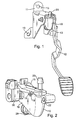
- Figure 1 shows a piston-master cylinder unit 10 with trained as a rotary valve piston for actuating a vehicle clutch, which is attached to a mounting bracket 11 and connected to an actuating pedal 12.
- the mounting bracket 11 itself is attached to the engine compartment of a vehicle via mounting holes 13 on the partition wall (not shown).
- FIGS. 2 to 4 show that the master cylinder comprises a plastic body 14 with an upper part 15 and a lower part 16. These two parts are connected by connecting pieces 17, which are arranged at intervals around the contact surface between the upper and lower part.
- Each connecting piece 17 comprises a flexible lock 18 on the upper part, which projects through a cast-on ring at the lower part 19 and engages under this.
- the upper part and the lower part are sealed against each other by a in the upper part 15 inserted into a groove 21 O-ring 20.
- the lower part 16 includes mounting holes 22 for attaching the master cylinder housing to the mounting bracket eleventh
- the top 15 also includes an inlet port 23 through which a connection is made to the associated liquid container (not shown).
- the lower part 16 includes an outlet opening 24 into which a connection piece 25 attached to a line 26 is inserted.
- the fitting 25 is sealed in the outlet opening 24 by an O-ring 27 and secured by a wire spring ring 28 in the outlet opening.
- the line 26 is connected to a slave cylinder (not shown).
- the lower part 16 also includes a working chamber 29, in which a rotary valve member 30 is rotatably mounted.
- the rotary valve member 30 is mounted on a shaft 31 which projects through the walls of the base 16 and is sealed against them.
- the actuating pedal 12 is connected to the shaft 31 such that upon passage of the pedal 12, the shaft 31 and thus the rotary valve member 30 in the working chamber 29 is rotated.
- a return spring (not shown) is incorporated, which acts on the pedal 12 and pushes the pedal back to the fully raised position shown in FIG.
- a rotation angle sensor 56 may be connected, which indicates the position of the pedal 12.
- the rotary valve member 30 is sealed in the working chamber 29 by an O-ring seal 32.
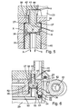
- a valve 33 (see Figure 5) is mounted, which has a closing body 34, a sleeve 35 in the bore 40 and a spring 36.
- the spring 36 acts between the closing body 34 and the sleeve 35.
- the spring 36 presses the closing body 34 formed on the valve seat 37 normally against the formed in the bore 40 sealing surface 38.
- the closing body 34 has a pin 41 which by an end portion 42 of Bore 40 protrudes and has a passage slot 43.
- the rotary valve member 30 begins to rotate in the direction Y in FIG. 4 so that the pin 41 no longer contacts the stop surface 44 and thus the valve seat 34 pushes against the sealing surface 38, thereby interrupting fluid flow through the rotary valve member 30 and the pressure in the working chamber 29 is increased below the rotary valve member 30, so that the slave cylinder connected to the line 26 functions normally.
- Figure 6 shows an alternative form in which similar functional elements as in Figure 5 are designated by like reference numerals.
- the sleeve 35 'in the part 50 of the rotary valve member 30 is integrated, which also includes a circumferential lip 51.
- the other part 52 of the rotary valve member 30 is made of a material such as nylon and has at the edge of a circumferential flexible lip 53, which acts as a seal of the rotary valve member 30.
- the lip 53 is pressed by a rubber filling 54 against the walls of the chamber 29, which is squeezed between the lips 51 and 53.
- the sleeve 35 ' is sealed in the bore 40' by an O-ring 55.
- Figure 7 shows an alternative arrangement in which components having a similar function as in Figures 1 to 5 are designated by like reference numerals.
- the seal 32 is not housed on the rotary valve member 30, but in a groove 16a in the lower part 16 of the master cylinder. Further, the rotary valve member 30 is fastened to the shaft 31 by means of a clamping screw 60.
Landscapes
- Engineering & Computer Science (AREA)
- Mechanical Engineering (AREA)
- General Engineering & Computer Science (AREA)
- Physics & Mathematics (AREA)
- Fluid Mechanics (AREA)
- Transportation (AREA)
- Hydraulic Clutches, Magnetic Clutches, Fluid Clutches, And Fluid Joints (AREA)
- Braking Systems And Boosters (AREA)
- Transmission Of Braking Force In Braking Systems (AREA)
- Chairs Characterized By Structure (AREA)
- Acyclic And Carbocyclic Compounds In Medicinal Compositions (AREA)
- Valve Device For Special Equipments (AREA)
- Supply Devices, Intensifiers, Converters, And Telemotors (AREA)
Abstract
Description
- Die vorliegende Erfindung betrifft einen hydraulischen Geberzylinder zum Betätigen von Baugruppen wie Fahrzeugkupplungen oder -bremsen, in denen im Geberzylinder im Betrieb der Druck einer Flüssigkeit erhöht wird, die über eine Auslassöffnung im Geberzylinder in einen Nehmerzylinder gedrückt wird, um die gewünschte Funktion auszuführen.
- Üblicherweise enthalten solche Geberzylinder einen Kolben, der durch Betätigung eines Pedals gleitend in einer Bohrung bewegt werden kann, um in einer Arbeitskammer den Druck einer Flüssigkeit zu erhöhen, die dann über die Auslassöffnung im Geberzylinder in den zugehörigen Nehmerzylinder gedrückt wird.
- Bei solchen Kolben-Geberzylindereinheiten treten Probleme auf, die mit der zuverlässigen Abdichtung des gleitenden Kolbens in der Bohrung und der Übertragung der Betätigungskraft vom Pedal auf den Kolben zusammenhängen.
- Eine Aufgabe der vorliegenden Erfindung besteht darin, einen verbesserten Geberzylinder bereitzustellen, der sich zur Verwendung beim Betätigen von Fahrzeugkupplungen und -bremsen eignet.
- Somit wird gemäß der vorliegenden Erfindung ein Geberzylinder mit einem als Drehschieberbauteil ausgebildeten Kolben bereitgestellt, der in einer Arbeitskammer im abgedichteten Zustand drehbar bewegt werden kann, wobei die Arbeitskammer eine mit einem Flüssigkeitsbehälter zu verbindende Einlassöffnung und eine mit einem Nehmerzylinder zu verbindende Auslassöffnung aufweist und das Drehen des Drehschieberbauteils so erfolgt, dass der Druck der Flüssigkeit auf einer Seite des Drehschiebers erhöht wird, um die Flüssigkeit durch die Auslassöffnung zu drücken.
- Bei einer bevorzugten Form der Erfindung ist das Drehschieberbauteil drehbar an einer Welle befestigt, die über die Kammer hinausragt, wobei das Drehschieberbauteil durch eine Drehung der Welle in Drehung versetzt und der Druck der Flüssigkeit erhöht wird.
- Vorzugsweise wird die Welle durch ein Betätigungspedal um ihre Achse gedreht.
- Vorzugsweise beinhaltet das Drehschieberbauteil ein Einwegventil, das sich schließt, wenn das Drehschieberbauteil gedreht wird, um den Druck der Flüssigkeit zu erhöhen, und das sich andererseits öffnet, damit die Flüssigkeit durch das Drehschieberbauteil fließen kann, wenn das Drehschieberbauteil plötzlich in der entgegengesetzten Richtung gedreht wird, was dann passieren kann, wenn der Fuß des Fahrzeugführers vom Betätigungspedal abrutscht (so genanntes "Rückspringen"). Dies trägt dazu bei, dass im Geberzylinder kein Unterdruck entsteht.
- Dieses Ventil ist auch so angeordnet, dass es die Flüssigkeit durch die Einlassöffnung und durch den Drehschieber in die Arbeitskammer und über die Auslassöffnung in den restlichen Teil des Betätigungssystems fließen lässt, wenn der Drehschieber vollständig zurückgesetzt ist. Dadurch kann über den Geberzylinder das zugehörige Betätigungssystem nachgefüllt werden, um den Verschleiß der vom Geberzylinder betätigten Kupplung oder Bremsen auszugleichen. Ferner wird durch das Ventil die Ersteinfüllung der Flüssigkeit aus dem zugehörigen Flüssigkeitsbehälter erleichtert.
- Im Folgenden wird anhand eines Beispiels und unter Bezug auf die beiliegenden Zeichnungen eine Ausführungsart der vorliegenden Erfindung beschrieben.
- Es zeigen:
- Figur 1 eine perspektivische Ansicht einer Kolben-Geberzylindereinheit gemäß der vorliegenden Erfindung, wobei der Kolben als Drehschieber ausgebildet ist, der an einer Befestigungsschelle angebracht ist und durch ein Pedal betätigt wird;
- Figur 2 eine perspektivische Ansicht des Geberzylinders mit einem optional vorgesehenen zugehörigen Drehwinkelsensor;
- Figur 3 und 4 vertikale Querschnitte durch den Körper des Geberzylinders, bei denen das Drehschieberbauteil vollständig zurückgesetzt bzw. nur teilweise um die Achse gedreht ist;
- Figur 5 die Wirkungsweise eines in den Drehschieber eingebauten Ventils in vergrößertem Maßstab;
- Figur 6 eine alternative Form der Dichtung zwischen Ventil und Drehschieber und
- Figur 7 eine alternative Anordnung von Drehschieberdichtung und Drehzapfen.
- Figur 1 zeigt eine Kolben-Geberzylindereinheit 10 mit als Drehschieber ausgebildetem Kolben zum Betätigen einer Fahrzeugkupplung, der an einer Befestigungsschelle 11 angebracht und mit einem Betätigungspedal 12 verbunden ist. Die Befestigungsschelle 11 selbst ist über Befestigungslöcher 13 an der (nicht gezeigten) Trennwand zum Motorraum eines Fahrzeugs angebracht.
- Die Figuren 2 bis 4 zeigen, dass der Geberzylinder einen Kunststoffkörper 14 mit einem Oberteil 15 und einem Unterteil 16 umfasst. Diese beiden Teile sind durch Verbindungsstücke 17 miteinander verbunden, die in Abständen um die Kontaktfläche zwischen Ober- und Unterteil herum angeordnet sind. Jedes Verbindungsstück 17 umfasst eine biegsame Verriegelung 18 am Oberteil, die durch einen am Unterteil angegossenen Ring 19 ragt und unter diesem einrastet. Das Oberteil und das Unterteil sind durch einen im Oberteil 15 in eine Nut 21 eingelegten O-Ring 20 gegeneinander abgedichtet. Der Unterteil 16 enthält Befestigungslöcher 22 zum Anbringen des Geberzylindergehäuses an der Befestigungsschelle 11.
- Das Oberteil 15 enthält auch eine Einlassöffnung 23, über die eine Verbindung zum (nicht gezeigten) zugehörigen Flüssigkeitsbehälter hergestellt wird.
- Das Unterteil 16 enthält eine Auslassöffnung 24, in welche ein an einer Leitung 26 befestigtes Anschlussstück 25 gesteckt ist. Das Anschlussstück 25 wird in der Auslassöffnung 24 durch einen O-Ring 27 abgedichtet und durch einen Drahtfederring 28 in der Auslassöffnung gesichert. Die Leitung 26 ist mit einem (nicht gezeigten) Nehmerzylinder verbunden.
- Das Unterteil 16 enthält auch eine Arbeitskammer 29, in der ein Drehschieberbauteil 30 drehbar gelagert ist. Das Drehschieberbauteil 30 ist auf einer Welle 31 befestigt, die durch die Wände des Unterteils 16 ragt und gegen diese abgedichtet ist. Das Betätigungspedal 12 ist so mit der Welle 31 verbunden, dass beim Durchtreten des Pedals 12 die Welle 31 und somit das Drehschieberbauteil 30 in der Arbeitskammer 29 in Drehung versetzt wird. Ferner ist eine (nicht gezeigte) Rückstellfeder eingebaut, die auf das Pedal 12 einwirkt und das Pedal in die in Figur 3 gezeigte vollständig angehobene Stellung zurückdrückt.
- Außerdem kann mit der Welle 31 auch ein Drehwinkelsensor 56 verbunden sein, der die Stellung des Pedals 12 anzeigt.
- Das Drehschieberbauteil 30 ist in der Arbeitskammer 29 durch eine O-Ringdichtung 32 abgedichtet. In einer Bohrung 40 im Drehschieberbauteil 30 ist ein Ventil 33 (siehe Figur 5) angebracht, das einen Schließkörper 34, eine Hülse 35 in der Bohrung 40 und eine Feder 36 aufweist. Die Feder 36 wirkt zwischen dem Schließkörper 34 und der Hülse 35. Die Feder 36 drückt den am Schließkörper 34 gebildeten Ventilsitz 37 normalerweise gegen die in der Bohrung 40 gebildete Dichtfläche 38. Der Schließkörper 34 weist einen Stift 41 auf, der durch einen Endteil 42 der Bohrung 40 ragt und einen Durchgangsschlitz 43 aufweist.
- Wenn sich das Drehschieberbauteil 30 gemäß Figur 3 in einer Endlage befindet (entsprechend der vollständig angehobenen Stellung des Pedals 12), stößt der Stift 41 gegen die Anschlagfläche 44 in der Einlassöffnung 23. Dadurch wirkt das Schließkörper 34 leicht dem Druck der Feder 36 entgegen, sodass der Ventilsitz 37 von der Dichtfläche 38 abhebt und die Flüssigkeit von der Einlassöffnung 23 über den Schlitz 43 zur anderen Seite des Drehschieberbauteils 30 fließen kann, was in Figur 5 durch die Pfeile X angezeigt wird. Dieser Flüssigkeitsstrom dient dazu, das System beim ersten Mal mit Flüssigkeit aus dem Flüssigkeitsbehälter zu füllen und Flüssigkeit durch das Drehschieberbauteil 30 fließen zu lassen, um die Flüssigkeit unterhalb des Drehschieberbauteils 30 aufzufüllen und so den Verschleiß der Kupplung zu kompensieren.
- Sobald das Pedal 12 niedergedrückt wird, beginnt sich das Drehschieberbauteil 30 in Richtung Y in Figur 4 zu drehen, sodass der Stift 41 nicht mehr die Anschlagfläche 44 berührt und somit der Ventilsitz 34 gegen die Dichtfläche 38 drückt, wodurch der Flüssigkeitsstrom durch das Drehschieberbauteil 30 unterbrochen und der Druck in der Arbeitskammer 29 unterhalb des Drehschieberbauteils 30 erhöht wird, sodass der mit der Leitung 26 verbundene Nehmerzylinder normal funktioniert.
- Sollte der Fuß des Fahrzeugführers zum Beispiel vom Pedal 12 abrutschen, sodass das Pedal 12 sofort hochspringt und das Drehschieberbauteil 30 in die in Figur 3 gezeigte Endstellung zurückkehrt (so genanntes "Rückspringen"), geht das Ventil 33 auf und die Flüssigkeit kann durch das Drehschieberbauteil 30 fließen, sodass unterhalb des Drehschieberbauteils 30 kein Unterdruck entstehen kann.
- Figur 6 zeigt eine alternative Form, bei welcher ähnliche Funktionselemente wie in Figur 5 durch gleiche Bezugsnummern bezeichnet sind. In Figur 6 ist die Hülse 35' in dem Teil 50 des Drehschieberbauteils 30 integriert, das auch eine umlaufende Lippe 51 enthält. Der andere Teil 52 des Drehschieberbauteils 30 besteht aus einem Material wie Nylon und weist am Rand eine umlaufende flexible Lippe 53 auf, die als Dichtung des Drehschieberbauteils 30 fungiert. Die Lippe 53 wird durch eine Gummifüllung 54 gegen die Wände der Kammer 29 gedrückt, die zwischen die Lippen 51 und 53 gequetscht wird. Die Hülse 35' wird in der Bohrung 40' durch einen O-Ring 55 abgedichtet.
- Figur 7 zeigt eine alternative Anordnung, bei der Bauteile mit ähnlicher Funktion wie in den Figuren 1 bis 5 durch gleiche Bezugsnummern bezeichnet werden. Bei dieser Anordnung ist die Dichtung 32 nicht am Drehschieberbauteil 30, sondern in einer Nut 16a im Unterteil 16 des Geberzylinders untergebracht. Ferner wird das Drehschieberbauteil 30 mittels einer Klemmschraube 60 an der Welle 31 befestigt.
Claims (9)
- Geberzylinder mit einem als Drehschieber ausgebildeten Kolben Drehschieberbauteil (30), der in einer Arbeitskammer im abgedichteten Zustand drehend bewegt werden kann, wobei die Arbeitskammer (29) eine mit einem Flüssigkeitsbehälter zu verbindende Einlassöffnung (23) und eine mit einem Nehmerzylinder zu verbindende Auslassöffnung aufweist, wobei durch das Drehen des Drehschieberbauteils (30) der Druck der Flüssigkeit auf einer Seite des Drehschieberbauteils (30) erhöht wird, um die Flüssigkeit durch die Auslassöffnung zu drücken.
- Geberzylinder nach Anspruch 1, bei welchem das Drehschieberbauteil (30) drehbar an einer Welle (31) befestigt ist, die über die Arbeitskammer (29) hinausragt, und durch die Drehung der Welle (31) das Drehschieberbauteil (30) in Drehung versetzt und dadurch der Druck der Flüssigkeit erhöht wird.
- Geberzylinder nach Anspruch 2, bei welchem die Welle (31) durch ein Betätigungspedal (12), in Drehung versetzt wird.
- Geberzylindern nach einem der Ansprüche 1 bis 3, bei welchem das Drehschieberbauteil (30) ein Einwegventil (33) enthält, das so angeordnet ist, dass es sich schließt, wenn das Drehschieberbauteil (30) gedreht wird, um den Druck der Flüssigkeit zu erhöhen, und dass es sich öffnet und die Flüssigkeit um das Drehschieberbauteil (30) herumfließen lässt, wenn das Drehschieberbauteil (30) plötzlich in der entgegengesetzten Richtung gedreht wird, was dann passieren kann, wenn der Fuß des Fahrzeugführers vom Betätigungspedal (12) abrutscht (so genanntes "Rückspringen").
- Geberzylindern nach Anspruch 4, bei welchem das Ventil (33) auch so angeordnet ist, dass die Flüssigkeit durch die Einlassöffnung (23) und durch das Drehschieberbauteil (30) in die Arbeitskammer (29) und über die Auslassöffnung in den restlichen Teil des Betätigungssystems fließen kann, wenn sich das Drehschieberbauteil (30) in einer vollständig zurückgesetzten Stellung befindet.
- Geberzylinder nach Anspruch 1, dadurch gekennzeichnet, dass das Drehschieberbauteil (30) aus Kunststoffmaterial gebildet ist und die Drehbewegung des Drehschieberbauteils (30) in der Arbeitskammer (29) dadurch abgedichtet wird, dass eine Kunststofflippe am Drehschieberbauteil gegen die Wände der Arbeitskammer (29) gedrückt wird.
- Geberzylinder nach Anspruch 6, dadurch gekennzeichnet, dass das Drehschieberbauteil (30) zwei Teile aufweist, wobei an einem Teil eine Dichtungslippe ausgebildet ist und zwischen die Dichtungslippe und dem anderen Teil des Drehschieberbauteils (30) ein elastisches Bauteil eingequetscht wird, damit die Dichtungslippe gegen die Wände der Arbeitskammer (29) gedrückt wird.
- Geberzylinder nach einem der Ansprüche 1 bis 7, dadurch gekennzeichnet, dass das Drehschieberbauteil (30) durch eine an diesem angebrachte Dichtung (32) gegen die Arbeitskammer (29) abgedichtet wird.
- Geberzylinder nach einem der Ansprüche 1 bis 7, dadurch gekennzeichnet, dass das Drehschieberbauteil (30) durch eine in den Wänden der Arbeitskammer (29) angebrachte Dichtung (32) gegen die Arbeitskammer abgedichtet wird.
Applications Claiming Priority (1)
| Application Number | Priority Date | Filing Date | Title |
|---|---|---|---|
| GBGB0504452.4A GB0504452D0 (en) | 2005-03-03 | 2005-03-03 | Master cylinders |
Publications (2)
| Publication Number | Publication Date |
|---|---|
| EP1698793A1 true EP1698793A1 (de) | 2006-09-06 |
| EP1698793B1 EP1698793B1 (de) | 2008-06-11 |
Family
ID=34430603
Family Applications (1)
| Application Number | Title | Priority Date | Filing Date |
|---|---|---|---|
| EP06002717A Expired - Lifetime EP1698793B1 (de) | 2005-03-03 | 2006-02-10 | Geberzylinder |
Country Status (4)
| Country | Link |
|---|---|
| EP (1) | EP1698793B1 (de) |
| AT (1) | ATE398247T1 (de) |
| DE (2) | DE502006000888D1 (de) |
| GB (1) | GB0504452D0 (de) |
Families Citing this family (1)
| Publication number | Priority date | Publication date | Assignee | Title |
|---|---|---|---|---|
| DE102006031012B4 (de) * | 2005-08-20 | 2016-01-07 | Schaeffler Technologies AG & Co. KG | Anordnung zur Kupplungsbetätigung |
Citations (5)
| Publication number | Priority date | Publication date | Assignee | Title |
|---|---|---|---|---|
| US2396155A (en) * | 1943-01-30 | 1946-03-05 | Niels A Christensen | Hydraulic brake |
| US4192224A (en) * | 1976-12-17 | 1980-03-11 | Toyota Jidosha Kogyo Kabushiki Kaisha | Rotary master cylinder means |
| EP0416189A1 (de) * | 1988-08-04 | 1991-03-13 | Bendix Espana S.A. | Rotationstandemhauptzylinder |
| DE4434254A1 (de) * | 1993-10-13 | 1995-04-20 | Schaeffler Waelzlager Kg | Pedal- und Geberzylindergestaltung |
| FR2755480A1 (fr) * | 1996-11-05 | 1998-05-07 | Peugeot | Dispositif de commande hydraulique pour actionner par une pedale un organe de vehicule automobile |
-
2005
- 2005-03-03 GB GBGB0504452.4A patent/GB0504452D0/en not_active Ceased
-
2006
- 2006-02-10 AT AT06002717T patent/ATE398247T1/de not_active IP Right Cessation
- 2006-02-10 EP EP06002717A patent/EP1698793B1/de not_active Expired - Lifetime
- 2006-02-10 DE DE502006000888T patent/DE502006000888D1/de not_active Expired - Lifetime
- 2006-02-10 DE DE102006006169A patent/DE102006006169A1/de not_active Withdrawn
Patent Citations (5)
| Publication number | Priority date | Publication date | Assignee | Title |
|---|---|---|---|---|
| US2396155A (en) * | 1943-01-30 | 1946-03-05 | Niels A Christensen | Hydraulic brake |
| US4192224A (en) * | 1976-12-17 | 1980-03-11 | Toyota Jidosha Kogyo Kabushiki Kaisha | Rotary master cylinder means |
| EP0416189A1 (de) * | 1988-08-04 | 1991-03-13 | Bendix Espana S.A. | Rotationstandemhauptzylinder |
| DE4434254A1 (de) * | 1993-10-13 | 1995-04-20 | Schaeffler Waelzlager Kg | Pedal- und Geberzylindergestaltung |
| FR2755480A1 (fr) * | 1996-11-05 | 1998-05-07 | Peugeot | Dispositif de commande hydraulique pour actionner par une pedale un organe de vehicule automobile |
Also Published As
| Publication number | Publication date |
|---|---|
| ATE398247T1 (de) | 2008-07-15 |
| DE102006006169A1 (de) | 2006-09-07 |
| DE502006000888D1 (de) | 2008-07-24 |
| EP1698793B1 (de) | 2008-06-11 |
| GB0504452D0 (en) | 2005-04-06 |
Similar Documents
| Publication | Publication Date | Title |
|---|---|---|
| DE102008030344B4 (de) | Kombiniertes Ansaugventil und elektrische Drucksteuerung für Farbsprühpumpen | |
| DE3013324A1 (de) | Pneumatische betaetigungsvorrichtung an einem spuelkasten-ablaufventil | |
| DE10163721A1 (de) | Rückschlagventil | |
| DE2258947C2 (de) | Hauptzylinder für ein hydraulisches Zweikreisbremssystem für Fahrzeuge | |
| DE2218112C3 (de) | Schmiereinrichtung für die Schneidketten von Motorkettensägen | |
| DE1505627A1 (de) | Druckabhalteventil fuer ein Bremssystem | |
| DE1653355A1 (de) | Membranpumpe,besonders zum Pumpen von dickfluessigen Fluessigkeiten | |
| EP1698793B1 (de) | Geberzylinder | |
| DE2111645A1 (de) | Druckluftbetriebene Kolbenpumpe,insbesondere Druckfluessigkeitspumpe fuer hydraulische Winden | |
| DE102005013409B4 (de) | Handkolbenpumpe mit blockierbarem Ausgabekopf zur Ausgabe von fluiden Substanzen | |
| DE112007002818B4 (de) | LUFTBETRIEBENE HYDRAULIKPUMPE MIT FUßBETÄTIGTEM LUFT- UND HYDRAULIKVENTIL | |
| DE69802665T2 (de) | Absperrventil für druckluftgesteuerte fahrzeugsysteme | |
| DE2457793B2 (de) | Fahrzeug-druckluftbremsanlage | |
| DE2250074C3 (de) | Blockierschutzeinrichtung für wenigstens ein Rad eines Kraftfahrzeuges mit einer pneumatischen Bremsanlage | |
| DE20213754U1 (de) | Ratschenvorrichtung für Schraubendreher | |
| DE2164160C3 (de) | Hydraulischer Hauptzyliner | |
| DE2831170C2 (de) | Drehschieberventil | |
| DE2045873A1 (de) | Ventil | |
| DE2236312C2 (de) | Feststellbremsventil für Druckluftbremsanlagen von Kraftfahrzeugen | |
| WO2014019868A1 (de) | Ventil einer speichereinrichtung mit einem öffnungsmittel | |
| DE69205516T2 (de) | Druckregelventil. | |
| DE10005902B4 (de) | Füllanschluß | |
| DE186505C (de) | ||
| DE102005002746B4 (de) | Düse | |
| DE19719877A1 (de) | Entlüftungsvorrichtung |
Legal Events
| Date | Code | Title | Description |
|---|---|---|---|
| PUAI | Public reference made under article 153(3) epc to a published international application that has entered the european phase |
Free format text: ORIGINAL CODE: 0009012 |
|
| AK | Designated contracting states |
Kind code of ref document: A1 Designated state(s): AT BE BG CH CY CZ DE DK EE ES FI FR GB GR HU IE IS IT LI LT LU LV MC NL PL PT RO SE SI SK TR |
|
| AX | Request for extension of the european patent |
Extension state: AL BA HR MK YU |
|
| 17P | Request for examination filed |
Effective date: 20070306 |
|
| 17Q | First examination report despatched |
Effective date: 20070404 |
|
| AKX | Designation fees paid |
Designated state(s): AT BE BG CH CY CZ DE DK EE ES FI FR GB GR HU IE IS IT LI LT LU LV MC NL PL PT RO SE SI SK TR |
|
| GRAP | Despatch of communication of intention to grant a patent |
Free format text: ORIGINAL CODE: EPIDOSNIGR1 |
|
| GRAS | Grant fee paid |
Free format text: ORIGINAL CODE: EPIDOSNIGR3 |
|
| GRAA | (expected) grant |
Free format text: ORIGINAL CODE: 0009210 |
|
| RAP1 | Party data changed (applicant data changed or rights of an application transferred) |
Owner name: LUK LAMELLEN UND KUPPLUNGSBAU BETEILIGUNGS KG |
|
| AK | Designated contracting states |
Kind code of ref document: B1 Designated state(s): AT BE BG CH CY CZ DE DK EE ES FI FR GB GR HU IE IS IT LI LT LU LV MC NL PL PT RO SE SI SK TR |
|
| REG | Reference to a national code |
Ref country code: GB Ref legal event code: FG4D Free format text: NOT ENGLISH |
|
| REG | Reference to a national code |
Ref country code: CH Ref legal event code: EP |
|
| REF | Corresponds to: |
Ref document number: 502006000888 Country of ref document: DE Date of ref document: 20080724 Kind code of ref document: P |
|
| REG | Reference to a national code |
Ref country code: IE Ref legal event code: FG4D Free format text: LANGUAGE OF EP DOCUMENT: GERMAN |
|
| PG25 | Lapsed in a contracting state [announced via postgrant information from national office to epo] |
Ref country code: SI Free format text: LAPSE BECAUSE OF FAILURE TO SUBMIT A TRANSLATION OF THE DESCRIPTION OR TO PAY THE FEE WITHIN THE PRESCRIBED TIME-LIMIT Effective date: 20080611 Ref country code: FI Free format text: LAPSE BECAUSE OF FAILURE TO SUBMIT A TRANSLATION OF THE DESCRIPTION OR TO PAY THE FEE WITHIN THE PRESCRIBED TIME-LIMIT Effective date: 20080611 |
|
| PG25 | Lapsed in a contracting state [announced via postgrant information from national office to epo] |
Ref country code: LV Free format text: LAPSE BECAUSE OF FAILURE TO SUBMIT A TRANSLATION OF THE DESCRIPTION OR TO PAY THE FEE WITHIN THE PRESCRIBED TIME-LIMIT Effective date: 20080611 Ref country code: PL Free format text: LAPSE BECAUSE OF FAILURE TO SUBMIT A TRANSLATION OF THE DESCRIPTION OR TO PAY THE FEE WITHIN THE PRESCRIBED TIME-LIMIT Effective date: 20080611 Ref country code: NL Free format text: LAPSE BECAUSE OF FAILURE TO SUBMIT A TRANSLATION OF THE DESCRIPTION OR TO PAY THE FEE WITHIN THE PRESCRIBED TIME-LIMIT Effective date: 20080611 |
|
| NLV1 | Nl: lapsed or annulled due to failure to fulfill the requirements of art. 29p and 29m of the patents act | ||
| PG25 | Lapsed in a contracting state [announced via postgrant information from national office to epo] |
Ref country code: CZ Free format text: LAPSE BECAUSE OF FAILURE TO SUBMIT A TRANSLATION OF THE DESCRIPTION OR TO PAY THE FEE WITHIN THE PRESCRIBED TIME-LIMIT Effective date: 20080611 Ref country code: SE Free format text: LAPSE BECAUSE OF FAILURE TO SUBMIT A TRANSLATION OF THE DESCRIPTION OR TO PAY THE FEE WITHIN THE PRESCRIBED TIME-LIMIT Effective date: 20080911 Ref country code: IS Free format text: LAPSE BECAUSE OF FAILURE TO SUBMIT A TRANSLATION OF THE DESCRIPTION OR TO PAY THE FEE WITHIN THE PRESCRIBED TIME-LIMIT Effective date: 20081011 Ref country code: LT Free format text: LAPSE BECAUSE OF FAILURE TO SUBMIT A TRANSLATION OF THE DESCRIPTION OR TO PAY THE FEE WITHIN THE PRESCRIBED TIME-LIMIT Effective date: 20080611 |
|
| PG25 | Lapsed in a contracting state [announced via postgrant information from national office to epo] |
Ref country code: PT Free format text: LAPSE BECAUSE OF FAILURE TO SUBMIT A TRANSLATION OF THE DESCRIPTION OR TO PAY THE FEE WITHIN THE PRESCRIBED TIME-LIMIT Effective date: 20081111 Ref country code: RO Free format text: LAPSE BECAUSE OF FAILURE TO SUBMIT A TRANSLATION OF THE DESCRIPTION OR TO PAY THE FEE WITHIN THE PRESCRIBED TIME-LIMIT Effective date: 20080611 Ref country code: ES Free format text: LAPSE BECAUSE OF FAILURE TO SUBMIT A TRANSLATION OF THE DESCRIPTION OR TO PAY THE FEE WITHIN THE PRESCRIBED TIME-LIMIT Effective date: 20080922 Ref country code: SK Free format text: LAPSE BECAUSE OF FAILURE TO SUBMIT A TRANSLATION OF THE DESCRIPTION OR TO PAY THE FEE WITHIN THE PRESCRIBED TIME-LIMIT Effective date: 20080611 |
|
| REG | Reference to a national code |
Ref country code: IE Ref legal event code: FD4D |
|
| PLBE | No opposition filed within time limit |
Free format text: ORIGINAL CODE: 0009261 |
|
| STAA | Information on the status of an ep patent application or granted ep patent |
Free format text: STATUS: NO OPPOSITION FILED WITHIN TIME LIMIT |
|
| PG25 | Lapsed in a contracting state [announced via postgrant information from national office to epo] |
Ref country code: EE Free format text: LAPSE BECAUSE OF FAILURE TO SUBMIT A TRANSLATION OF THE DESCRIPTION OR TO PAY THE FEE WITHIN THE PRESCRIBED TIME-LIMIT Effective date: 20080611 Ref country code: BG Free format text: LAPSE BECAUSE OF FAILURE TO SUBMIT A TRANSLATION OF THE DESCRIPTION OR TO PAY THE FEE WITHIN THE PRESCRIBED TIME-LIMIT Effective date: 20080911 Ref country code: DK Free format text: LAPSE BECAUSE OF FAILURE TO SUBMIT A TRANSLATION OF THE DESCRIPTION OR TO PAY THE FEE WITHIN THE PRESCRIBED TIME-LIMIT Effective date: 20080611 Ref country code: IE Free format text: LAPSE BECAUSE OF FAILURE TO SUBMIT A TRANSLATION OF THE DESCRIPTION OR TO PAY THE FEE WITHIN THE PRESCRIBED TIME-LIMIT Effective date: 20080611 |
|
| 26N | No opposition filed |
Effective date: 20090312 |
|
| BERE | Be: lapsed |
Owner name: LUK LAMELLEN UND KUPPLUNGSBAU BETEILIGUNGS K.G. Effective date: 20090228 |
|
| PG25 | Lapsed in a contracting state [announced via postgrant information from national office to epo] |
Ref country code: IT Free format text: LAPSE BECAUSE OF FAILURE TO SUBMIT A TRANSLATION OF THE DESCRIPTION OR TO PAY THE FEE WITHIN THE PRESCRIBED TIME-LIMIT Effective date: 20080611 |
|
| PG25 | Lapsed in a contracting state [announced via postgrant information from national office to epo] |
Ref country code: MC Free format text: LAPSE BECAUSE OF NON-PAYMENT OF DUE FEES Effective date: 20090228 |
|
| PG25 | Lapsed in a contracting state [announced via postgrant information from national office to epo] |
Ref country code: BE Free format text: LAPSE BECAUSE OF NON-PAYMENT OF DUE FEES Effective date: 20090228 |
|
| PGFP | Annual fee paid to national office [announced via postgrant information from national office to epo] |
Ref country code: FR Payment date: 20100319 Year of fee payment: 5 |
|
| PG25 | Lapsed in a contracting state [announced via postgrant information from national office to epo] |
Ref country code: AT Free format text: LAPSE BECAUSE OF NON-PAYMENT OF DUE FEES Effective date: 20090210 |
|
| PGFP | Annual fee paid to national office [announced via postgrant information from national office to epo] |
Ref country code: DE Payment date: 20100430 Year of fee payment: 5 |
|
| REG | Reference to a national code |
Ref country code: CH Ref legal event code: PL |
|
| GBPC | Gb: european patent ceased through non-payment of renewal fee |
Effective date: 20100210 |
|
| PG25 | Lapsed in a contracting state [announced via postgrant information from national office to epo] |
Ref country code: GR Free format text: LAPSE BECAUSE OF FAILURE TO SUBMIT A TRANSLATION OF THE DESCRIPTION OR TO PAY THE FEE WITHIN THE PRESCRIBED TIME-LIMIT Effective date: 20080912 Ref country code: CH Free format text: LAPSE BECAUSE OF NON-PAYMENT OF DUE FEES Effective date: 20100228 Ref country code: LI Free format text: LAPSE BECAUSE OF NON-PAYMENT OF DUE FEES Effective date: 20100228 |
|
| PG25 | Lapsed in a contracting state [announced via postgrant information from national office to epo] |
Ref country code: GB Free format text: LAPSE BECAUSE OF NON-PAYMENT OF DUE FEES Effective date: 20100210 |
|
| PG25 | Lapsed in a contracting state [announced via postgrant information from national office to epo] |
Ref country code: LU Free format text: LAPSE BECAUSE OF NON-PAYMENT OF DUE FEES Effective date: 20090210 |
|
| PG25 | Lapsed in a contracting state [announced via postgrant information from national office to epo] |
Ref country code: HU Free format text: LAPSE BECAUSE OF FAILURE TO SUBMIT A TRANSLATION OF THE DESCRIPTION OR TO PAY THE FEE WITHIN THE PRESCRIBED TIME-LIMIT Effective date: 20081212 |
|
| PG25 | Lapsed in a contracting state [announced via postgrant information from national office to epo] |
Ref country code: TR Free format text: LAPSE BECAUSE OF FAILURE TO SUBMIT A TRANSLATION OF THE DESCRIPTION OR TO PAY THE FEE WITHIN THE PRESCRIBED TIME-LIMIT Effective date: 20080611 |
|
| PG25 | Lapsed in a contracting state [announced via postgrant information from national office to epo] |
Ref country code: CY Free format text: LAPSE BECAUSE OF FAILURE TO SUBMIT A TRANSLATION OF THE DESCRIPTION OR TO PAY THE FEE WITHIN THE PRESCRIBED TIME-LIMIT Effective date: 20080611 |
|
| REG | Reference to a national code |
Ref country code: FR Ref legal event code: ST Effective date: 20111102 |
|
| REG | Reference to a national code |
Ref country code: DE Ref legal event code: R119 Ref document number: 502006000888 Country of ref document: DE Effective date: 20110901 |
|
| PG25 | Lapsed in a contracting state [announced via postgrant information from national office to epo] |
Ref country code: FR Free format text: LAPSE BECAUSE OF NON-PAYMENT OF DUE FEES Effective date: 20110228 |
|
| PG25 | Lapsed in a contracting state [announced via postgrant information from national office to epo] |
Ref country code: DE Free format text: LAPSE BECAUSE OF NON-PAYMENT OF DUE FEES Effective date: 20110901 |
|
| P01 | Opt-out of the competence of the unified patent court (upc) registered |
Effective date: 20230523 |