EP1698397B1 - Wabenstruktur - Google Patents
Wabenstruktur Download PDFInfo
- Publication number
- EP1698397B1 EP1698397B1 EP06251110A EP06251110A EP1698397B1 EP 1698397 B1 EP1698397 B1 EP 1698397B1 EP 06251110 A EP06251110 A EP 06251110A EP 06251110 A EP06251110 A EP 06251110A EP 1698397 B1 EP1698397 B1 EP 1698397B1
- Authority
- EP
- European Patent Office
- Prior art keywords
- peripheral wall
- outer peripheral
- honeycomb structure
- thickness
- region
- Prior art date
- Legal status (The legal status is an assumption and is not a legal conclusion. Google has not performed a legal analysis and makes no representation as to the accuracy of the status listed.)
- Ceased
Links
Images


Classifications
-
- C—CHEMISTRY; METALLURGY
- C04—CEMENTS; CONCRETE; ARTIFICIAL STONE; CERAMICS; REFRACTORIES
- C04B—LIME, MAGNESIA; SLAG; CEMENTS; COMPOSITIONS THEREOF, e.g. MORTARS, CONCRETE OR LIKE BUILDING MATERIALS; ARTIFICIAL STONE; CERAMICS; REFRACTORIES; TREATMENT OF NATURAL STONE
- C04B38/00—Porous mortars, concrete, artificial stone or ceramic ware; Preparation thereof
- C04B38/0006—Honeycomb structures
-
- B—PERFORMING OPERATIONS; TRANSPORTING
- B01—PHYSICAL OR CHEMICAL PROCESSES OR APPARATUS IN GENERAL
- B01D—SEPARATION
- B01D46/00—Filters or filtering processes specially modified for separating dispersed particles from gases or vapours
- B01D46/24—Particle separators, e.g. dust precipitators, using rigid hollow filter bodies
- B01D46/2403—Particle separators, e.g. dust precipitators, using rigid hollow filter bodies characterised by the physical shape or structure of the filtering element
- B01D46/2418—Honeycomb filters
- B01D46/2451—Honeycomb filters characterized by the geometrical structure, shape, pattern or configuration or parameters related to the geometry of the structure
- B01D46/2462—Honeycomb filters characterized by the geometrical structure, shape, pattern or configuration or parameters related to the geometry of the structure the outer peripheral sealing
-
- B—PERFORMING OPERATIONS; TRANSPORTING
- B01—PHYSICAL OR CHEMICAL PROCESSES OR APPARATUS IN GENERAL
- B01D—SEPARATION
- B01D46/00—Filters or filtering processes specially modified for separating dispersed particles from gases or vapours
- B01D46/24—Particle separators, e.g. dust precipitators, using rigid hollow filter bodies
- B01D46/2403—Particle separators, e.g. dust precipitators, using rigid hollow filter bodies characterised by the physical shape or structure of the filtering element
- B01D46/2418—Honeycomb filters
- B01D46/2451—Honeycomb filters characterized by the geometrical structure, shape, pattern or configuration or parameters related to the geometry of the structure
- B01D46/247—Honeycomb filters characterized by the geometrical structure, shape, pattern or configuration or parameters related to the geometry of the structure of the cells
-
- B—PERFORMING OPERATIONS; TRANSPORTING
- B01—PHYSICAL OR CHEMICAL PROCESSES OR APPARATUS IN GENERAL
- B01D—SEPARATION
- B01D46/00—Filters or filtering processes specially modified for separating dispersed particles from gases or vapours
- B01D46/24—Particle separators, e.g. dust precipitators, using rigid hollow filter bodies
- B01D46/2403—Particle separators, e.g. dust precipitators, using rigid hollow filter bodies characterised by the physical shape or structure of the filtering element
- B01D46/2418—Honeycomb filters
- B01D46/2451—Honeycomb filters characterized by the geometrical structure, shape, pattern or configuration or parameters related to the geometry of the structure
- B01D46/2474—Honeycomb filters characterized by the geometrical structure, shape, pattern or configuration or parameters related to the geometry of the structure of the walls along the length of the honeycomb
-
- B—PERFORMING OPERATIONS; TRANSPORTING
- B01—PHYSICAL OR CHEMICAL PROCESSES OR APPARATUS IN GENERAL
- B01D—SEPARATION
- B01D46/00—Filters or filtering processes specially modified for separating dispersed particles from gases or vapours
- B01D46/24—Particle separators, e.g. dust precipitators, using rigid hollow filter bodies
- B01D46/2403—Particle separators, e.g. dust precipitators, using rigid hollow filter bodies characterised by the physical shape or structure of the filtering element
- B01D46/2418—Honeycomb filters
- B01D46/2451—Honeycomb filters characterized by the geometrical structure, shape, pattern or configuration or parameters related to the geometry of the structure
- B01D46/2482—Thickness, height, width, length or diameter
-
- B—PERFORMING OPERATIONS; TRANSPORTING
- B01—PHYSICAL OR CHEMICAL PROCESSES OR APPARATUS IN GENERAL
- B01D—SEPARATION
- B01D46/00—Filters or filtering processes specially modified for separating dispersed particles from gases or vapours
- B01D46/24—Particle separators, e.g. dust precipitators, using rigid hollow filter bodies
- B01D46/2403—Particle separators, e.g. dust precipitators, using rigid hollow filter bodies characterised by the physical shape or structure of the filtering element
- B01D46/2418—Honeycomb filters
- B01D46/2451—Honeycomb filters characterized by the geometrical structure, shape, pattern or configuration or parameters related to the geometry of the structure
- B01D46/2486—Honeycomb filters characterized by the geometrical structure, shape, pattern or configuration or parameters related to the geometry of the structure characterised by the shapes or configurations
- B01D46/249—Quadrangular e.g. square or diamond
-
- B—PERFORMING OPERATIONS; TRANSPORTING
- B01—PHYSICAL OR CHEMICAL PROCESSES OR APPARATUS IN GENERAL
- B01D—SEPARATION
- B01D46/00—Filters or filtering processes specially modified for separating dispersed particles from gases or vapours
- B01D46/24—Particle separators, e.g. dust precipitators, using rigid hollow filter bodies
- B01D46/2403—Particle separators, e.g. dust precipitators, using rigid hollow filter bodies characterised by the physical shape or structure of the filtering element
- B01D46/2418—Honeycomb filters
- B01D46/2498—The honeycomb filter being defined by mathematical relationships
-
- B—PERFORMING OPERATIONS; TRANSPORTING
- B01—PHYSICAL OR CHEMICAL PROCESSES OR APPARATUS IN GENERAL
- B01D—SEPARATION
- B01D53/00—Separation of gases or vapours; Recovering vapours of volatile solvents from gases; Chemical or biological purification of waste gases, e.g. engine exhaust gases, smoke, fumes, flue gases, aerosols
- B01D53/34—Chemical or biological purification of waste gases
- B01D53/92—Chemical or biological purification of waste gases of engine exhaust gases
- B01D53/94—Chemical or biological purification of waste gases of engine exhaust gases by catalytic processes
- B01D53/9445—Simultaneously removing carbon monoxide, hydrocarbons or nitrogen oxides making use of three-way catalysts [TWC] or four-way-catalysts [FWC]
- B01D53/9454—Simultaneously removing carbon monoxide, hydrocarbons or nitrogen oxides making use of three-way catalysts [TWC] or four-way-catalysts [FWC] characterised by a specific device
-
- B—PERFORMING OPERATIONS; TRANSPORTING
- B01—PHYSICAL OR CHEMICAL PROCESSES OR APPARATUS IN GENERAL
- B01J—CHEMICAL OR PHYSICAL PROCESSES, e.g. CATALYSIS OR COLLOID CHEMISTRY; THEIR RELEVANT APPARATUS
- B01J35/00—Catalysts, in general, characterised by their form or physical properties
- B01J35/50—Catalysts, in general, characterised by their form or physical properties characterised by their shape or configuration
- B01J35/56—Foraminous structures having flow-through passages or channels, e.g. grids or three-dimensional monoliths
- B01J35/57—Honeycombs
-
- F—MECHANICAL ENGINEERING; LIGHTING; HEATING; WEAPONS; BLASTING
- F01—MACHINES OR ENGINES IN GENERAL; ENGINE PLANTS IN GENERAL; STEAM ENGINES
- F01N—GAS-FLOW SILENCERS OR EXHAUST APPARATUS FOR MACHINES OR ENGINES IN GENERAL; GAS-FLOW SILENCERS OR EXHAUST APPARATUS FOR INTERNAL-COMBUSTION ENGINES
- F01N3/00—Exhaust or silencing apparatus having means for purifying, rendering innocuous, or otherwise treating exhaust
- F01N3/02—Exhaust or silencing apparatus having means for purifying, rendering innocuous, or otherwise treating exhaust for cooling, or for removing solid constituents of, exhaust
- F01N3/021—Exhaust or silencing apparatus having means for purifying, rendering innocuous, or otherwise treating exhaust for cooling, or for removing solid constituents of, exhaust by means of filters
- F01N3/022—Exhaust or silencing apparatus having means for purifying, rendering innocuous, or otherwise treating exhaust for cooling, or for removing solid constituents of, exhaust by means of filters characterised by specially adapted filtering structure, e.g. honeycomb, mesh or fibrous
- F01N3/0222—Exhaust or silencing apparatus having means for purifying, rendering innocuous, or otherwise treating exhaust for cooling, or for removing solid constituents of, exhaust by means of filters characterised by specially adapted filtering structure, e.g. honeycomb, mesh or fibrous the structure being monolithic, e.g. honeycombs
-
- B—PERFORMING OPERATIONS; TRANSPORTING
- B28—WORKING CEMENT, CLAY, OR STONE
- B28B—SHAPING CLAY OR OTHER CERAMIC COMPOSITIONS; SHAPING SLAG; SHAPING MIXTURES CONTAINING CEMENTITIOUS MATERIAL, e.g. PLASTER
- B28B3/00—Producing shaped articles from the material by using presses; Presses specially adapted therefor
- B28B3/20—Producing shaped articles from the material by using presses; Presses specially adapted therefor wherein the material is extruded
- B28B3/26—Extrusion dies
- B28B3/269—For multi-channeled structures, e.g. honeycomb structures
-
- C—CHEMISTRY; METALLURGY
- C04—CEMENTS; CONCRETE; ARTIFICIAL STONE; CERAMICS; REFRACTORIES
- C04B—LIME, MAGNESIA; SLAG; CEMENTS; COMPOSITIONS THEREOF, e.g. MORTARS, CONCRETE OR LIKE BUILDING MATERIALS; ARTIFICIAL STONE; CERAMICS; REFRACTORIES; TREATMENT OF NATURAL STONE
- C04B2111/00—Mortars, concrete or artificial stone or mixtures to prepare them, characterised by specific function, property or use
- C04B2111/00474—Uses not provided for elsewhere in C04B2111/00
- C04B2111/00793—Uses not provided for elsewhere in C04B2111/00 as filters or diaphragms
-
- C—CHEMISTRY; METALLURGY
- C04—CEMENTS; CONCRETE; ARTIFICIAL STONE; CERAMICS; REFRACTORIES
- C04B—LIME, MAGNESIA; SLAG; CEMENTS; COMPOSITIONS THEREOF, e.g. MORTARS, CONCRETE OR LIKE BUILDING MATERIALS; ARTIFICIAL STONE; CERAMICS; REFRACTORIES; TREATMENT OF NATURAL STONE
- C04B2111/00—Mortars, concrete or artificial stone or mixtures to prepare them, characterised by specific function, property or use
- C04B2111/00474—Uses not provided for elsewhere in C04B2111/00
- C04B2111/0081—Uses not provided for elsewhere in C04B2111/00 as catalysts or catalyst carriers
-
- F—MECHANICAL ENGINEERING; LIGHTING; HEATING; WEAPONS; BLASTING
- F01—MACHINES OR ENGINES IN GENERAL; ENGINE PLANTS IN GENERAL; STEAM ENGINES
- F01N—GAS-FLOW SILENCERS OR EXHAUST APPARATUS FOR MACHINES OR ENGINES IN GENERAL; GAS-FLOW SILENCERS OR EXHAUST APPARATUS FOR INTERNAL-COMBUSTION ENGINES
- F01N2330/00—Structure of catalyst support or particle filter
- F01N2330/06—Ceramic, e.g. monoliths
-
- F—MECHANICAL ENGINEERING; LIGHTING; HEATING; WEAPONS; BLASTING
- F01—MACHINES OR ENGINES IN GENERAL; ENGINE PLANTS IN GENERAL; STEAM ENGINES
- F01N—GAS-FLOW SILENCERS OR EXHAUST APPARATUS FOR MACHINES OR ENGINES IN GENERAL; GAS-FLOW SILENCERS OR EXHAUST APPARATUS FOR INTERNAL-COMBUSTION ENGINES
- F01N2340/00—Dimensional characteristics of the exhaust system, e.g. length, diameter or volume of the exhaust apparatus; Spatial arrangements of exhaust apparatuses
-
- Y—GENERAL TAGGING OF NEW TECHNOLOGICAL DEVELOPMENTS; GENERAL TAGGING OF CROSS-SECTIONAL TECHNOLOGIES SPANNING OVER SEVERAL SECTIONS OF THE IPC; TECHNICAL SUBJECTS COVERED BY FORMER USPC CROSS-REFERENCE ART COLLECTIONS [XRACs] AND DIGESTS
- Y02—TECHNOLOGIES OR APPLICATIONS FOR MITIGATION OR ADAPTATION AGAINST CLIMATE CHANGE
- Y02T—CLIMATE CHANGE MITIGATION TECHNOLOGIES RELATED TO TRANSPORTATION
- Y02T10/00—Road transport of goods or passengers
- Y02T10/10—Internal combustion engine [ICE] based vehicles
- Y02T10/12—Improving ICE efficiencies
-
- Y—GENERAL TAGGING OF NEW TECHNOLOGICAL DEVELOPMENTS; GENERAL TAGGING OF CROSS-SECTIONAL TECHNOLOGIES SPANNING OVER SEVERAL SECTIONS OF THE IPC; TECHNICAL SUBJECTS COVERED BY FORMER USPC CROSS-REFERENCE ART COLLECTIONS [XRACs] AND DIGESTS
- Y10—TECHNICAL SUBJECTS COVERED BY FORMER USPC
- Y10T—TECHNICAL SUBJECTS COVERED BY FORMER US CLASSIFICATION
- Y10T428/00—Stock material or miscellaneous articles
- Y10T428/24—Structurally defined web or sheet [e.g., overall dimension, etc.]
- Y10T428/24149—Honeycomb-like
Definitions
- the present invention relates to a honeycomb structure, more particularly to a honeycomb structure which is resistant to a thermal shock and in which any crack is not easily developed entirely, even if the crack is generated.
- a honeycomb structure made of ceramic is used for trapping a particulate matter such as dust contained in an exhaust gas from a car, an incineration exhaust gas or the like, and further for adsorbing and absorbing NOx, CO, HC and the like from the exhaust gas by a coated substrate.
- Such honeycomb structure frequently undergoes a thermal shock, when heated by a high-temperature exhaust gas or the like.
- the present invention has been developed in view of the above-described problems, and an object is to provide a honeycomb structure which is capable of avoiding a problem of thermal shock and in which a crack is not easily developed entirely, even if the crack is generated and whose catalyst carrying property is satisfactory.
- the average value (Tp) of the partition wall thicknesses is 0.038 mm ⁇ Tp ⁇ 0.43 mm.
- each cell perpendicular to the axial direction has a quadrangular shape.
- the region from the 0° direction (first 0° direction) to the 90° direction (first 90° direction) in the section perpendicular to the axial direction is a first region, and subsequent regions formed every 90° are second to fourth regions, respectively, at least one of the second to fourth regions satisfies the conditions 1 and/or 2.
- the average value (Ts) of the outer peripheral wall thickness is Tp ⁇ Ts ⁇ 10 x Tp (Tp: average value of the partition wall thicknesses), and the outer peripheral wall thickness in the specific position is set to be smaller than that in the other position. Therefore, a stress during heating or cooling is moderated by the thinly formed portion of the outer peripheral wall, and the honeycomb structure is resistant to a thermal shock. Even if a crack is generated, the crack is easily generated in the thinly formed outer peripheral wall. When the crack is generated in the thin portion of the outer peripheral wall in this manner, the crack is not easily developed to the partition walls as compared with the crack which is generated in a thick portion of the outer peripheral wall. Since the outer peripheral wall does not have any missing portion such as a slit, any trouble is not caused even in a catalyst coating or the like.
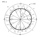
- FIG. 1 is a sectional view schematically showing a part of a honeycomb structure cut along a plane perpendicular an axial direction of the structure in one embodiment of the present invention.
- the section cut along the plane which is perpendicular to the axial direction of the honeycomb structure will be hereinafter sometimes referred to simply as the "section perpendicular to the axial direction”.
- a honeycomb structure 100 of the present embodiment includes: partition walls 1 formed so as to define a plurality of cells 8 extending in an axial direction; and an outer peripheral wall 2 disposed so as to surround the partition walls 1.
- an average value (Ts) of an outer peripheral wall thickness is Tp ⁇ Ts ⁇ 10 ⁇ Tp (Tp: average value of partition wall thicknesses), and the outer peripheral wall thickness in a specific position is set to be smaller than that in another position.
- Tp average value of partition wall thicknesses
- each cell 8 perpendicular to the axial direction has a quadrangular shape.
- the average value (Ts) of the outer peripheral wall thicknesses is preferably Tp ⁇ Ts ⁇ 8 ⁇ Tp, more preferably Tp ⁇ TS ⁇ 6 ⁇ Tp.
- Ts is not more than Tp
- an outer wall breaks under a stress from the outside, such as a stress due to canning.
- the value is larger than 10 ⁇ Tp, a thermal stress generated between the partition wall and the outer peripheral wall increases.
- the average value of the outer peripheral wall thicknesses is a value obtained by measuring the outer peripheral wall thicknesses every 45° from a 0° position of the outer peripheral wall, and calculating an average of eight measurements.
- the average value of the partition wall thicknesses is obtained by calculating an average of 20 partition wall thicknesses in total including: partition wall thicknesses in ten equally divided positions of a diameter connecting the 0° position to a 180° position; and those in ten equally divided positions of a diameter connecting a 90° direction to a 270° direction.
- the average value is obtained by calculating an average of 20 partition wall thicknesses including: partition wall thicknesses in ten equally divided positions of a long diameter; and those in ten equally divided positions of a short diameter.
- the honeycomb structure of the present embodiment preferably satisfies the following conditions 1 and/or 2:
- the thinnest outer peripheral wall in the region 7 of 30° to 60° of the outer peripheral wall corresponds to the thinly formed portion of the outer peripheral wall.
- This region is sometimes referred to as the thin wall region 7.
- 0.1 ⁇ Ts 0 ⁇ T S30-60 ⁇ 0.8 ⁇ Ts 0 is further preferable, and 0.2 ⁇ Ts 0 ⁇ TS 30-60 ⁇ 0.6 ⁇ Ts 0 is especially preferable.
- 0.1 ⁇ Ts 90 ⁇ TS 30-60 ⁇ 0.8 ⁇ TS 90 is further preferable, and 0.2 ⁇ Ts 90 ⁇ TS 30-60 ⁇ 0.6 ⁇ TS 90 is especially preferable.
- a width (angle) of the thinnest portion is 0° to 15°, wherein "0°" is not included.
- the honeycomb structure When each cell has a square shape in the section perpendicular to the axial direction, the honeycomb structure does not easily expand or contract in a longitudinal direction (0° and 90° directions in FIG. 1 ) of each partition wall in the section, and the structure tends to easily expands and contracts closer to an intermediate direction (45° direction in FIG. 1 ). Therefore, when the honeycomb structure undergoes a thermal shock, the partition wall tends to be largely deformed closer to the intermediate direction.
- the thickness of the thinnest outer peripheral wall in the region (thin wall region) 7 of 30° to 60° of the outer peripheral wall is smaller than 90% of TS 0 and/or TS 90 .
- this thin wall region 7 is easily deformed centering on the thinnest portion as compared with another portion of the outer peripheral wall. As described above, when the partition wall is largely deformed centering on the intermediate direction, the thin wall region 7 brought into contact with the partition wall can also be deformed largely. Therefore, a stress due to the thermal shock is relaxed.
- the honeycomb structure sometimes becomes vulnerable to the thermal shock. Furthermore, if a crack is generated, the crack is sometimes easily developed to the partition wall.
- the region (region of 30° to 60° of the outer peripheral wall) 7 from the 30° direction to the 60° direction refers to an outer peripheral wall in a region from an outer peripheral wall 5a in the 30° direction as the portion of a straight line (30° direction line) 5 extending in the 30° direction, which crosses the outer peripheral wall 2, to an outer peripheral wall 6a in the 60° direction as the portion of a straight line (60° direction line) 6 extending in the 60° direction, which crosses the outer peripheral wall 2.
- the outer peripheral wall 4a in the 90° direction is a portion of a straight line (90° direction line) 4 extending in the 90° direction, which crosses the outer peripheral wall 2.
- the 30° direction line 5 is a straight line which forms an angle ⁇ of 30° with respect to the 0° direction line 3
- the 60° direction line 6 is a straight line which forms an angle ⁇ of 60° with respect to the 0° direction line 3.
- the 90° direction line 4 is a straight line which forms an angle ⁇ of 90° with respect to the 0° direction line 3.
- the average value (Tp) of the partition wall thicknesses is preferably 0.038 mm ⁇ Tp ⁇ 0.43 mm, more preferably 0.050 mm ⁇ Tp ⁇ 0.31 mm.
- Tp the average value of the partition wall thicknesses
- the region from the 0° direction (first 0° direction) to the 90° direction (first 90° direction) in the section perpendicular to the axial direction is a first region X
- subsequent regions formed every 90° are a second region Y (region Y), a third region Z (region Z), and a fourth region W (region W), respectively
- at least one of the second region Y to the fourth region W satisfies the conditions 1 and/or 2.
- the honeycomb structure of the present embodiment becomes more resistant to the thermal shock.
- the 90° direction line 4 in the region X is superimposed on a 0° direction line (second 0° direction line) 13 in the region Y, and a position of 90° from this second 0° direction line 13 is a second 90° direction line 14.
- the region Y is surrounded with the second 0° direction line 13 and the second 90° direction line 14.
- a position of 30° from the second 0° direction line 13 is a second 30° direction line 15, and a position of 60° from the second 0° direction line is a second 60° direction line 16.
- An outer peripheral wall positioned between the second 30° direction line 15 and the second 60° direction line 16 is a region (second thin wall region) 17 of the outer peripheral wall.
- the region Z is a region surrounded with a third 0° direction line 23 and a third 90° direction line 24, and an outer peripheral wall positioned between a third 30° direction line 25 and a third 60° direction line 26 is a region (third thin wall region) 27 of 30° to 60° of the outer peripheral wall.
- the region W is a region surrounded with a fourth 0° direction line 33 and a fourth 90° direction line 34, and an outer peripheral wall positioned between a fourth 30° direction line 35 and a fourth 60° direction line 36 is a region (fourth thin wall region) 37 of 30° to 60° of the outer peripheral wall.
- an average value (Ts) of outer peripheral wall thicknesses is preferably 0.1 mm ⁇ Ts ⁇ 3 mm, more preferably 0.2 mm ⁇ Ts ⁇ 2 mm.
- the honeycomb structure easily breaks.
- the value is larger than 3 mm, the structure is deformed, or becomes excessively heavy during manufacturing.
- a honeycomb structure 100 is a columnar structure in which a plurality of cells 8 are defined by partition walls 1, and an outer peripheral wall 2 is disposed in an outer periphery of the structure so as to surround the partition walls 1.
- the shape is preferably columnar as shown in FIG. 3 , but the shape may be a prismatic shape such as a square pole shape.
- the present embodiment is preferably usable in a honeycomb structure having a circle diameter of 40 to 310 mm and an axial-direction length of 10 to 310 mm.
- the material is preferably a ceramic, and cordierite is preferable among ceramic mat among ceramic materials.
- the material is preferably porous, an average pore diameter is preferably 3 to 30 ⁇ m, and a porosity is preferably 28 to 60%.
- the average pore diameter is a value measured by a method of "Total Pore Volume and Median Pore Diameter described in 6.3 of M505-87 Test Method of Car Exhaust Gas Purifying Catalyst Ceramic Monolith Carrier, JASO Car Standards".
- the porosity is a value calculated from a pore volume.
- a cell density is preferably 15 to 186 cells/cm 2 .
- the honeycomb structure of the present embodiment can be obtained by: kneading predetermined forming materials to prepare a clay; forming the prepared clay to prepare a honeycomb-shaped formed body; drying the body to prepare a dried honeycomb formed body; and firing the resultant dried honeycomb formed body.
- a method of kneading the forming materials to prepare the clay there is not any special restriction on a method of kneading the forming materials to prepare the clay, and examples of the method include a method using a kneader, a vacuum clay kneader or the like.
- the predetermined forming materials can be appropriately selected depending on desired materials.
- the method is extruding the clay prepared as described above by use of a die having a desired outer peripheral wall thickness, a desired partition wall thickness, and a desired cell density.
- the outer peripheral wall thickness in a specific position needs to be set to be smaller than that in another position.
- This method is as follows. That is, a supply amount of the clay to a place to be thinned is reduced by changing a back hole diameter or arrangement of the die, or a shape of a pressing plate for use in forming the outer peripheral wall. Accordingly, the specific position is formed to be thin, and a difference is made in the outer peripheral wall thickness.
- a drying method which has heretofore been known is usable such as hot-air drying, microwave drying, dielectric drying, reduced-pressure drying, vacuum drying, or freeze-drying.
- a preferable drying method is a drying method obtained by combining the hot-air drying with the microwave drying or the dielectric drying, because the whole formed body can be quickly and uniformly dried. Drying conditions can be appropriately selected in accordance with the shape, the material or the like of the honeycomb formed body.
- the honeycomb formed body dried by the above method is fired in a firing furnace, so that the honeycomb structure of the present embodiment can be obtained.
- the firing furnace and firing conditions can be appropriately selected in accordance with the shape, the material or the like of the honeycomb formed body. Calcination may be performed before the firing to burn and remove organic matters such as a binder.
- Alumina, talc, and kaolin were used as forming materials. These materials were kneaded with a kneader to prepare a clay.
- the resultant clay was extruded into a honeycomb shape by use of a die so as to obtain a cell structure of 3.5 mil/600 cpsi ("0.09 mm"/"93 cells/cm 2 ”) and a honeycomb structure outer diameter of 143.8 mm ⁇ .
- honeycomb structures were formed so that "Ts 0 :TS 30-60 " of a portion corresponding to a first region in a section perpendicular to an axial direction, and an "average outer peripheral wall thickness (average outer wall thickness)" II of a honeycomb-shaped formed body were: 1:0.95 (average outer wall thickness of 0.20 mm) (Example 1); 1:0.90 (average outer wall thickness of 0.23 mm) (Example 2); 1:0.70 (average outer wall thickness of 0.26 mm) (Example 3); 1:0.60 (average outer wall thickness of 0.27 mm) (Example 4); 1:0.50 (average outer wall thickness of 0.30 mm) (Example 5); and 1:0.40 (average outer wall thickness of 0.31 mm) (Example 6).
- the resultant honeycomb-shaped formed bodies were dried to prepare dried honeycomb formed bodies, and the resultant dried honeycomb formed bodies were fired to obtain honeycomb structures (Examples 1 to 6).
- Example 1 The honeycomb structures of Examples 1 to 6 were subjected to an isostatic strength test on the following conditions. Three types of samples having total lengths of 101.6 mm, 139.7 mm, and 152.4 mm were prepared as samples for the test from the honeycomb structure of each example. Results are shown in Table 1. Results indicate average values of three types of samples. [Table 1] Isostatic strength (kgf / cm 2 ) Example 1 Average 38.4 Example 2 Average 46.3 Example 3 Average 38.9 Example 4 Average 50.6 Example 5 Average 62.6 Example 6 Average 52.7
- honeycomb structures were prepared in the same manner as in Examples 1 to 6 except that a honeycomb structure outer diameter was set to 80.0 mm ⁇ (Examples 7 to 12).
- Honeycomb structures were prepared in the same manner as in Examples 1 to 6 except that a honeycomb , structure outer diameter was set to 90.0 mm ⁇ (Examples 13 to 18).
- honeycomb structures were prepared in the same manner as in Examples 1 to 6 except that a honeycomb structure outer diameter was set to 100.0 mm ⁇ (Examples 19 to 24).
- honeycomb structures were prepared in the same manner as in Examples 1 to 6 except that a honeycomb structure outer diameter was set to 110.0 mm ⁇ (Examples 25 to 30).
- honeycomb structures were prepared in the same manner as in Examples 1 to 6 except that a honeycomb structure outer diameter was set to 132.1 mm ⁇ (Examples 31 to 36).
- Honeycomb structures were prepared in the same manner as in Examples 1 to 6 except that a cell structure was set to 2.5 mil/900 cpsi ("0.065 mm"/"140 cells/cm 2 ”) and a honeycomb structure outer diameter was set to 76.0 mm ⁇ (Examples 37 to 42).
- honeycomb structures were prepared in the same manner as in Examples 37 to 42 except that a honeycomb structure outer diameter was set to 90.0 mm ⁇ (Examples 43 to 48).
- honeycomb structures were prepared in the same manner as in Examples 37 to 42 except that a honeycomb structure outer diameter was set to 100.0 mm ⁇ (Examples 49 to 54).
- Honeycomb structures were prepared in the same manner as in Examples 37 to 42 except that a honeycomb structure outer diameter was set to 103.0 mm ⁇ (Examples 55 to 60).
- honeycomb structures were prepared in the same manner as in Examples 37 to 42 except that a honeycomb structure outer diameter was set to 105.7 mm ⁇ (Examples 61 to 66).
- Honeycomb structures were prepared in the same manner as in Examples 37 to 42 except that a honeycomb structure outer diameter was set to 118.4 mm ⁇ (Examples 67 to 72).
- the honeycomb structures of Examples 1 to 72 were subjected to a thermal shock resistance test on the following conditions. Three types of samples having total lengths of 101.6 mm, 139.7 mm, and 152.4 mm were prepared from the.honeycomb structure of each example. Results are shown in FIG. 4 .
- a thermal shock resistance test was carried out in conformity with "Thermal Shock Resistance Test" described in 6.7 of M505-87 in the test method of the car exhaust gas purifying catalyst ceramic monolith carrier of the JASO car standards.
- any crack was not generated, it was judged that the sample passed the test.
- the crack was generated in a partition wall portion, it was judged that the sample failed.
- Even when the crack was generated in the outer peripheral wall it was judged that the sample passed the test.
- the outer peripheral wall crack was developed to the partition wall, it was judged that the sample failed.
- temperature was raised every 50°C from 700°C, and the test was carried out up to 900°C (with the proviso that the test was ended in a case where the sample failed halfway).
- a pass ratio of the thermal shock resistance test is a ratio of the number of passed samples with respect to all of the samples in a case where a "ratio of TS 30-60 (outer wall thickness ratio) with respect to TS 0 " had an equal value (e.g., 0.95).
- the present invention is usable for trapping a particulate matter such as dust contained in an exhaust gas from a car, an incineration exhaust gas generated during incineration of wastes or the like, and further for adsorbing and absorbing NOx, CO, HC and the like from the exhaust gas by a coated substrate.
Landscapes
- Chemical & Material Sciences (AREA)
- Geometry (AREA)
- Physics & Mathematics (AREA)
- Engineering & Computer Science (AREA)
- Chemical Kinetics & Catalysis (AREA)
- Combustion & Propulsion (AREA)
- Organic Chemistry (AREA)
- Materials Engineering (AREA)
- Ceramic Engineering (AREA)
- Health & Medical Sciences (AREA)
- General Engineering & Computer Science (AREA)
- General Chemical & Material Sciences (AREA)
- Analytical Chemistry (AREA)
- Environmental & Geological Engineering (AREA)
- Structural Engineering (AREA)
- Biomedical Technology (AREA)
- Oil, Petroleum & Natural Gas (AREA)
- Mechanical Engineering (AREA)
- Exhaust Gas After Treatment (AREA)
- Exhaust Gas Treatment By Means Of Catalyst (AREA)
- Catalysts (AREA)
- Processes For Solid Components From Exhaust (AREA)
- Filtering Of Dispersed Particles In Gases (AREA)
Claims (9)
- Wabenstruktur, die Folgendes umfasst:Trennwände (1), die ausgebildet sind, um eine Vielzahl an Zellen (8) zu definieren, die sich in axialer Richtung erstrecken; undeine äußere Umfangswand (2), die angeordnet ist, um die Trennwände zu umgeben,wobei die Wabenstruktur, die die Trennwände (1) und die Umfangswand (2) umfasst, wie folgt erhalten wird: durch Extrusionsformen eines Tons zur Ausbildung eines Wabenformkörpers, der sowohl Trennwände als auch eine Umfangswand umfasst, unter Verwendung einer Düse mit einer gewünschten Außenumfangswanddicke, einer gewünschten Trennwanddicke und einer gewünschten Zelldichte, gefolgt vom Trocknen und Brennen des wabenförmigen Formkörpers, wodurch die Wabenstruktur mit den Trennwänden (1) und der Außenumfangswand (2) erhalten wird,
wobei der Mittelwert (Ts) der Dicke der Außenumfangswand (2) folgende Beziehung erfüllt:Tp < Ts ≤ 10 x Tp, worin Tp der Mittelwert der Dicke der Trennwände (1) ist, undwobei unter der Annahme, dass eine Richtung, die sich vom Mittelpunkt der axialen Endfläche der Wabenstruktur parallel zu den Trennwänden zu der Außenumfangswand (2) erstreckt, eine "0°-Richtung" ist und die Länge einer geraden Linie, die sich in die 0°-Richtung erstreckt und die Außenumfangswand schneidet, die "Dicke (Ts0) der Außenumfangswand in der 0°-Richtung" ist, die folgenden Bedingungen 1 und/oder 2 erfüllt werden:Bedingung 1: die Beziehung zwischen der Dicke (Ts0) der Außenumfangswand (2) in der 0°-Richtung und der Dicke (Ts30-60) der dünnsten Außenumfangswand in einem Bereich von einer 30°-Richtung zu einer 60°-Richtung ausgehend von der 0°-Richtung Tp < Ts30-60 < 0,90 x Ts0 ist; undBedingung 2: die Beziehung zwischen der Dicke (Ts90) der Außenumfangswand (2) in einer 90°-Richtung ausgehend von der 0°-Richtung und der Dicke Ts30-60 Tp < Ts30-60 < 0,90 x Ts90 ist, undwobei die Winkelbreite der dünnsten Umfangswand im Bereich von der 30°-Richtung bis zu der 60°-Richtung größer als 0° und geringer oder gleich 15° ist. - Wabenstruktur nach Anspruch 1, worin der Mittelwert (Tp) der Trennwanddicke 0,038 mm ≤ Tp ≤ 0,43 mm ist.
- Wabenstruktur nach Anspruch 2, worin der Mittelwert (Tp) der Trennwanddicke 0,050 mm ≤ Tp ≤ 0,31 mm ist.
- Wabenstruktur nach Anspruch 1, 2 oder 3, worin ein Abschnitt jeder Zelle im rechten Winkel auf die Achsenrichtung eine viereckige Form aufweist.
- Wabenstruktur nach einem der Ansprüche 1 bis 4, worin unter der Annahme, dass der Bereich von der 0°-Richtung (erste 0°-Richtung) zu der 90°-Richtung (erste 90°-Richtung) in dem Abschnitt, der im rechten Winkel auf die Achsenrichtung steht, ein erster Bereich ist und die folgenden Bereiche, die alle 90° ausgebildet sind, dem zweiten bis vierten Bereich entsprechen, wobei zumindest einer der zweiten bis vierten Bereiche die Bedingung 1 und/oder 2 erfüllt.
- Wabenstruktur nach einem der vorangegangenen Ansprüche, worin in Bedingung 1 gilt 0,1 x Ts0 < Ts30-60 < 0,8 x Ts0 und/oder in Bedingung 2 gilt 0,1 x Ts90 < Ts30-60 < 0,8 x TS90.
- Wabenstruktur nach Anspruch 6, worin in Bedingung 1 gilt 0,2 x Ts0 < Ts30-60 < 0,6 x Ts0 und/oder in Bedingung 2 gilt 0,2 x Ts90 < Ts30-60 < 0,6 x Ts90.
- Wabenstruktur nach einem der vorangegangenen Ansprüche, worin der Mittelwert (Ts) der Dicke der Außenumfangswand 0,1 mm ≤ Ts ≤ 3 mm beträgt.
- Wabenstruktur nach Anspruch 8, worin der Mittelwert (Ts) der Dicke der Außenumfangswand 0,2 mm ≤ Ts ≤ 2 mm beträgt.
Applications Claiming Priority (1)
| Application Number | Priority Date | Filing Date | Title |
|---|---|---|---|
| JP2005060087A JP5026674B2 (ja) | 2005-03-04 | 2005-03-04 | ハニカム構造体 |
Publications (2)
| Publication Number | Publication Date |
|---|---|
| EP1698397A1 EP1698397A1 (de) | 2006-09-06 |
| EP1698397B1 true EP1698397B1 (de) | 2011-05-04 |
Family
ID=36475336
Family Applications (1)
| Application Number | Title | Priority Date | Filing Date |
|---|---|---|---|
| EP06251110A Ceased EP1698397B1 (de) | 2005-03-04 | 2006-03-01 | Wabenstruktur |
Country Status (4)
| Country | Link |
|---|---|
| US (1) | US20060198984A1 (de) |
| EP (1) | EP1698397B1 (de) |
| JP (1) | JP5026674B2 (de) |
| DE (1) | DE602006021652D1 (de) |
Families Citing this family (15)
| Publication number | Priority date | Publication date | Assignee | Title |
|---|---|---|---|---|
| FR2906159B1 (fr) * | 2006-09-27 | 2008-10-31 | Saint Gobain Ct Recherches | Element monolithique a coins renforces pour la filtration de particules |
| US8016906B2 (en) * | 2007-05-04 | 2011-09-13 | Dow Global Technologies Llc | Honeycomb filter elements |
| JPWO2009035049A1 (ja) * | 2007-09-14 | 2010-12-24 | 日本碍子株式会社 | ハニカムフィルタの製造方法 |
| JP4896171B2 (ja) * | 2009-03-13 | 2012-03-14 | 日本碍子株式会社 | ハニカムフィルタの製造方法 |
| JP5064432B2 (ja) * | 2009-03-24 | 2012-10-31 | 日本碍子株式会社 | ハニカム触媒体 |
| US8491295B2 (en) | 2009-05-28 | 2013-07-23 | Corning Incorporated | Die assembly and method of extruding cellular ceramic substrates with a skin |
| JP5762138B2 (ja) * | 2011-05-28 | 2015-08-12 | 京セラ株式会社 | ハニカム構造体およびこれを用いたガス処理装置 |
| JP5908345B2 (ja) * | 2011-06-07 | 2016-04-26 | 住友化学株式会社 | ハニカム構造体成形用金型及びこれを用いたハニカム構造体の製造方法 |
| US9475245B2 (en) * | 2012-05-08 | 2016-10-25 | Corning Incorporated | Honeycomb extrusion apparatus and methods |
| JP6041902B2 (ja) | 2012-12-27 | 2016-12-14 | 住友化学株式会社 | ハニカムフィルタ及びその製造方法 |
| JP6563542B1 (ja) * | 2018-02-27 | 2019-08-21 | 本田技研工業株式会社 | 排気浄化装置 |
| JP6797147B2 (ja) * | 2018-03-27 | 2020-12-09 | 日本碍子株式会社 | ハニカム成形体及びハニカム構造体の製造方法 |
| EP3801827B1 (de) | 2018-05-31 | 2025-12-17 | Corning Incorporated | Wabenkörper mit wabenstrukturverstärkungsmerkmalen und extrusionsmatrizen dafür |
| WO2021138034A1 (en) * | 2020-01-03 | 2021-07-08 | Corning Incorporated | Ceramic honeycomb articles with improved isostatic strength, and method for fabricating same |
| JP7305695B2 (ja) * | 2021-03-26 | 2023-07-10 | 日本碍子株式会社 | 柱状ハニカム焼成体の製造方法 |
Family Cites Families (9)
| Publication number | Priority date | Publication date | Assignee | Title |
|---|---|---|---|---|
| JPS55142189A (en) * | 1979-04-24 | 1980-11-06 | Ngk Spark Plug Co | Honeycomb structure body |
| JP2613729B2 (ja) * | 1992-01-30 | 1997-05-28 | 日本碍子株式会社 | セラミックハニカム構造体及びその製造法並びにそのためのコート材 |
| JP3777895B2 (ja) | 1999-08-11 | 2006-05-24 | 株式会社デンソー | セラミックハニカム構造体 |
| JP2001261428A (ja) * | 2000-03-14 | 2001-09-26 | Ngk Insulators Ltd | セラミックハニカム構造体 |
| JP4216174B2 (ja) * | 2003-01-09 | 2009-01-28 | 日本碍子株式会社 | コート材、セラミックスハニカム構造体及びその製造方法 |
| JPWO2004078674A1 (ja) * | 2003-03-05 | 2006-06-08 | 日本碍子株式会社 | ハニカム構造体、及びその製造方法 |
| JP2005007218A (ja) * | 2003-06-16 | 2005-01-13 | Hitachi Metals Ltd | セラミックハニカム構造体及びセラミックハニカム構造体用金型 |
| EP1679120B1 (de) * | 2003-07-28 | 2018-08-22 | NGK Insulators, Ltd. | Wabenstruktur und herstellungsverfahren dafür |
| JP2005230680A (ja) * | 2004-02-19 | 2005-09-02 | Ngk Insulators Ltd | ハニカム構造体 |
-
2005
- 2005-03-04 JP JP2005060087A patent/JP5026674B2/ja not_active Expired - Fee Related
-
2006
- 2006-02-24 US US11/360,698 patent/US20060198984A1/en not_active Abandoned
- 2006-03-01 EP EP06251110A patent/EP1698397B1/de not_active Ceased
- 2006-03-01 DE DE602006021652T patent/DE602006021652D1/de active Active
Also Published As
| Publication number | Publication date |
|---|---|
| US20060198984A1 (en) | 2006-09-07 |
| DE602006021652D1 (de) | 2011-06-16 |
| EP1698397A1 (de) | 2006-09-06 |
| JP5026674B2 (ja) | 2012-09-12 |
| JP2006239603A (ja) | 2006-09-14 |
Similar Documents
| Publication | Publication Date | Title |
|---|---|---|
| EP1698397B1 (de) | Wabenstruktur | |
| EP2705891B1 (de) | Abgedichtete Wabenstruktur | |
| US7981496B2 (en) | Honeycomb structured body | |
| EP1847519B1 (de) | Wabenstruktur und Herstellungsverfahren dafür | |
| US9340463B2 (en) | Honeycomb structure | |
| US7083842B2 (en) | Honeycomb structure and process for production thereof | |
| EP1977828A1 (de) | Katalysatorträger und Abgasreinigungsvorrichtung | |
| JP4706784B2 (ja) | 六角セルハニカム構造体 | |
| US20080241008A1 (en) | Catalyst carrier and exhaust gas treatment apparatus | |
| US10632647B2 (en) | Honeycomb structure | |
| US20100242426A1 (en) | Ceramic honeycomb structure | |
| EP1728544A1 (de) | Wabenstruktur und herstellungsverfahren dafür | |
| JP5378994B2 (ja) | ハニカムセグメント成形用口金、及びハニカム構造体の製造方法 | |
| JP2003340224A (ja) | ハニカム構造体、及びその製造方法 | |
| US11285468B2 (en) | Honeycomb structure | |
| US10730804B2 (en) | Honeycomb structure | |
| US9463407B2 (en) | Honeycomb structure | |
| EP3081282B1 (de) | Wabenstruktur und herstellungsverfahren für wabenstruktur | |
| US10435331B2 (en) | Honeycomb structure | |
| US10253665B2 (en) | Honeycomb structure | |
| EP2626123B1 (de) | Wabenstruktur-Katalysatorkörper | |
| US11135576B2 (en) | Honeycomb structure | |
| EP2567745A1 (de) | Wabenförmiger Katalysatorträger | |
| US11471869B2 (en) | Honeycomb structure |
Legal Events
| Date | Code | Title | Description |
|---|---|---|---|
| PUAI | Public reference made under article 153(3) epc to a published international application that has entered the european phase |
Free format text: ORIGINAL CODE: 0009012 |
|
| AK | Designated contracting states |
Kind code of ref document: A1 Designated state(s): AT BE BG CH CY CZ DE DK EE ES FI FR GB GR HU IE IS IT LI LT LU LV MC NL PL PT RO SE SI SK TR |
|
| AX | Request for extension of the european patent |
Extension state: AL BA HR MK YU |
|
| 17P | Request for examination filed |
Effective date: 20070302 |
|
| AKX | Designation fees paid |
Designated state(s): DE FR |
|
| 17Q | First examination report despatched |
Effective date: 20080326 |
|
| GRAP | Despatch of communication of intention to grant a patent |
Free format text: ORIGINAL CODE: EPIDOSNIGR1 |
|
| GRAS | Grant fee paid |
Free format text: ORIGINAL CODE: EPIDOSNIGR3 |
|
| GRAA | (expected) grant |
Free format text: ORIGINAL CODE: 0009210 |
|
| AK | Designated contracting states |
Kind code of ref document: B1 Designated state(s): DE FR |
|
| REF | Corresponds to: |
Ref document number: 602006021652 Country of ref document: DE Date of ref document: 20110616 Kind code of ref document: P |
|
| REG | Reference to a national code |
Ref country code: DE Ref legal event code: R096 Ref document number: 602006021652 Country of ref document: DE Effective date: 20110616 |
|
| PLBE | No opposition filed within time limit |
Free format text: ORIGINAL CODE: 0009261 |
|
| STAA | Information on the status of an ep patent application or granted ep patent |
Free format text: STATUS: NO OPPOSITION FILED WITHIN TIME LIMIT |
|
| 26N | No opposition filed |
Effective date: 20120207 |
|
| REG | Reference to a national code |
Ref country code: DE Ref legal event code: R097 Ref document number: 602006021652 Country of ref document: DE Effective date: 20120207 |
|
| REG | Reference to a national code |
Ref country code: FR Ref legal event code: PLFP Year of fee payment: 11 |
|
| REG | Reference to a national code |
Ref country code: FR Ref legal event code: PLFP Year of fee payment: 12 |
|
| PGFP | Annual fee paid to national office [announced via postgrant information from national office to epo] |
Ref country code: FR Payment date: 20170213 Year of fee payment: 12 |
|
| PG25 | Lapsed in a contracting state [announced via postgrant information from national office to epo] |
Ref country code: FR Free format text: LAPSE BECAUSE OF NON-PAYMENT OF DUE FEES Effective date: 20180331 |
|
| REG | Reference to a national code |
Ref country code: DE Ref legal event code: R079 Ref document number: 602006021652 Country of ref document: DE Free format text: PREVIOUS MAIN CLASS: B01J0035040000 Ipc: B01J0035560000 |
|
| PGFP | Annual fee paid to national office [announced via postgrant information from national office to epo] |
Ref country code: DE Payment date: 20240130 Year of fee payment: 19 |
|
| REG | Reference to a national code |
Ref country code: DE Ref legal event code: R119 Ref document number: 602006021652 Country of ref document: DE |
|
| PG25 | Lapsed in a contracting state [announced via postgrant information from national office to epo] |
Ref country code: DE Free format text: LAPSE BECAUSE OF NON-PAYMENT OF DUE FEES Effective date: 20251001 |