EP1697675B1 - Steckverbinder für medienleitungen - Google Patents
Steckverbinder für medienleitungen Download PDFInfo
- Publication number
- EP1697675B1 EP1697675B1 EP04804926A EP04804926A EP1697675B1 EP 1697675 B1 EP1697675 B1 EP 1697675B1 EP 04804926 A EP04804926 A EP 04804926A EP 04804926 A EP04804926 A EP 04804926A EP 1697675 B1 EP1697675 B1 EP 1697675B1
- Authority
- EP
- European Patent Office
- Prior art keywords
- plug
- media
- seal
- plug connector
- plugged
- Prior art date
- Legal status (The legal status is an assumption and is not a legal conclusion. Google has not performed a legal analysis and makes no representation as to the accuracy of the status listed.)
- Not-in-force
Links
- 239000012530 fluid Substances 0.000 title abstract 5
- 238000007789 sealing Methods 0.000 claims abstract description 16
- 239000002184 metal Substances 0.000 claims description 3
- 239000000463 material Substances 0.000 claims description 2
- 238000003780 insertion Methods 0.000 abstract description 19
- 230000037431 insertion Effects 0.000 abstract description 19
- 238000000465 moulding Methods 0.000 description 2
- 229910001369 Brass Inorganic materials 0.000 description 1
- 239000010951 brass Substances 0.000 description 1
- 230000001419 dependent effect Effects 0.000 description 1
- 239000000428 dust Substances 0.000 description 1
- 238000007373 indentation Methods 0.000 description 1
- 238000004519 manufacturing process Methods 0.000 description 1
- 238000000034 method Methods 0.000 description 1
- 238000010137 moulding (plastic) Methods 0.000 description 1
- 230000002093 peripheral effect Effects 0.000 description 1
- 239000007921 spray Substances 0.000 description 1
- XLYOFNOQVPJJNP-UHFFFAOYSA-N water Substances O XLYOFNOQVPJJNP-UHFFFAOYSA-N 0.000 description 1
Images

Classifications
-
- F—MECHANICAL ENGINEERING; LIGHTING; HEATING; WEAPONS; BLASTING
- F16—ENGINEERING ELEMENTS AND UNITS; GENERAL MEASURES FOR PRODUCING AND MAINTAINING EFFECTIVE FUNCTIONING OF MACHINES OR INSTALLATIONS; THERMAL INSULATION IN GENERAL
- F16L—PIPES; JOINTS OR FITTINGS FOR PIPES; SUPPORTS FOR PIPES, CABLES OR PROTECTIVE TUBING; MEANS FOR THERMAL INSULATION IN GENERAL
- F16L37/00—Couplings of the quick-acting type
- F16L37/08—Couplings of the quick-acting type in which the connection between abutting or axially overlapping ends is maintained by locking members
- F16L37/084—Couplings of the quick-acting type in which the connection between abutting or axially overlapping ends is maintained by locking members combined with automatic locking
- F16L37/092—Couplings of the quick-acting type in which the connection between abutting or axially overlapping ends is maintained by locking members combined with automatic locking by means of elements wedged between the pipe and the frusto-conical surface of the body of the connector
- F16L37/0925—Couplings of the quick-acting type in which the connection between abutting or axially overlapping ends is maintained by locking members combined with automatic locking by means of elements wedged between the pipe and the frusto-conical surface of the body of the connector with rings which bite into the wall of the pipe
-
- F—MECHANICAL ENGINEERING; LIGHTING; HEATING; WEAPONS; BLASTING
- F16—ENGINEERING ELEMENTS AND UNITS; GENERAL MEASURES FOR PRODUCING AND MAINTAINING EFFECTIVE FUNCTIONING OF MACHINES OR INSTALLATIONS; THERMAL INSULATION IN GENERAL
- F16L—PIPES; JOINTS OR FITTINGS FOR PIPES; SUPPORTS FOR PIPES, CABLES OR PROTECTIVE TUBING; MEANS FOR THERMAL INSULATION IN GENERAL
- F16L37/00—Couplings of the quick-acting type
- F16L37/08—Couplings of the quick-acting type in which the connection between abutting or axially overlapping ends is maintained by locking members
- F16L37/084—Couplings of the quick-acting type in which the connection between abutting or axially overlapping ends is maintained by locking members combined with automatic locking
- F16L37/092—Couplings of the quick-acting type in which the connection between abutting or axially overlapping ends is maintained by locking members combined with automatic locking by means of elements wedged between the pipe and the frusto-conical surface of the body of the connector
- F16L37/0926—Couplings of the quick-acting type in which the connection between abutting or axially overlapping ends is maintained by locking members combined with automatic locking by means of elements wedged between the pipe and the frusto-conical surface of the body of the connector with an inner support sleeve arranged within the pipe
-
- F—MECHANICAL ENGINEERING; LIGHTING; HEATING; WEAPONS; BLASTING
- F16—ENGINEERING ELEMENTS AND UNITS; GENERAL MEASURES FOR PRODUCING AND MAINTAINING EFFECTIVE FUNCTIONING OF MACHINES OR INSTALLATIONS; THERMAL INSULATION IN GENERAL
- F16L—PIPES; JOINTS OR FITTINGS FOR PIPES; SUPPORTS FOR PIPES, CABLES OR PROTECTIVE TUBING; MEANS FOR THERMAL INSULATION IN GENERAL
- F16L2201/00—Special arrangements for pipe couplings
- F16L2201/10—Indicators for correct coupling
-
- F—MECHANICAL ENGINEERING; LIGHTING; HEATING; WEAPONS; BLASTING
- F16—ENGINEERING ELEMENTS AND UNITS; GENERAL MEASURES FOR PRODUCING AND MAINTAINING EFFECTIVE FUNCTIONING OF MACHINES OR INSTALLATIONS; THERMAL INSULATION IN GENERAL
- F16L—PIPES; JOINTS OR FITTINGS FOR PIPES; SUPPORTS FOR PIPES, CABLES OR PROTECTIVE TUBING; MEANS FOR THERMAL INSULATION IN GENERAL
- F16L2201/00—Special arrangements for pipe couplings
- F16L2201/30—Detecting leaks
-
- F—MECHANICAL ENGINEERING; LIGHTING; HEATING; WEAPONS; BLASTING
- F16—ENGINEERING ELEMENTS AND UNITS; GENERAL MEASURES FOR PRODUCING AND MAINTAINING EFFECTIVE FUNCTIONING OF MACHINES OR INSTALLATIONS; THERMAL INSULATION IN GENERAL
- F16L—PIPES; JOINTS OR FITTINGS FOR PIPES; SUPPORTS FOR PIPES, CABLES OR PROTECTIVE TUBING; MEANS FOR THERMAL INSULATION IN GENERAL
- F16L2201/00—Special arrangements for pipe couplings
- F16L2201/80—Dust covers
-
- Y—GENERAL TAGGING OF NEW TECHNOLOGICAL DEVELOPMENTS; GENERAL TAGGING OF CROSS-SECTIONAL TECHNOLOGIES SPANNING OVER SEVERAL SECTIONS OF THE IPC; TECHNICAL SUBJECTS COVERED BY FORMER USPC CROSS-REFERENCE ART COLLECTIONS [XRACs] AND DIGESTS
- Y10—TECHNICAL SUBJECTS COVERED BY FORMER USPC
- Y10S—TECHNICAL SUBJECTS COVERED BY FORMER USPC CROSS-REFERENCE ART COLLECTIONS [XRACs] AND DIGESTS
- Y10S285/00—Pipe joints or couplings
- Y10S285/924—Vented
Definitions
- the present invention relates to a connector for media lines according to the preamble of claim 1.
- the EP 0 733 844 B1 describes such a connection device with the features of the preamble of claim 1.
- the bipartite of the housing part allows for easy assembly and disassembly and a release of the male part.
- the insert consists of a one-piece plastic molded part, wherein a dirt seal to prevent the ingress of dust, dirt, moisture (spray water) and the like, is integrally formed as a circumferential sealing lip.
- a dirt seal to prevent the ingress of dust, dirt, moisture (spray water) and the like, is integrally formed as a circumferential sealing lip.
- the insert part has two elastic latching arms, which engage with latching lugs in the base part and in there formed latching openings. Each latching arm has an outwardly projecting from the base portion actuating portion.
- the publication US 2003/0178846 A1 describes a conduit connector, which consists of a tubular, curved connecting body made of plastic and a connecting part made of metal.
- the connecting part is inserted into the connecting body with a plug-in section, the plug-in section having on its outer circumference a tooth-like annular projection with a sharp cross-section which engages in the cylindrical inner surface of the connecting body.
- a plug-in receptacle for a cable is formed on the opposite side of the connecting body , And within the plug receptacle, a holding element for locking and a media seal for sealing the conduit are arranged.
- connection part - analogous to the connection part - has on its outer periphery a sharp, tooth-shaped annular projection which cuts into the cylindrical inner surface of the connecting body.
- the guide part - analogous to the connection part - has on its outer periphery a sharp, tooth-shaped annular projection which cuts into the cylindrical inner surface of the connecting body.
- the present invention has for its object to further improve a connector of the type mentioned and simplify.
- the base part in turn is also in two parts from a receiving part for the holding element, the media seal and the insert part and formed from a connection part for connection of the housing part to a media line, advantageously being provided between the receiving part and the connector means for securing against relative rotation.
- means are provided for securing the entire inserted plug-in part against rotation about the plug-in axis relative to the connector according to the invention.
- the means for preventing rotation are in this case formed by interlocking elements such that the items are axially mounted, but secured against Relatiwerpitung.
- the connector is also suitable for angle connectors, where it depends on a direction adjustment.
- the holding element for locking the inserted plug-in part and subsequently the media seal are arranged inside the plug-in receptacle, starting from a muzzle-side dirt seal, wherein a leakage path is formed such that in one of the holding element locked, but not yet sealed via the media seal Vorarretier ein the plug a defined limited, physically detectable leakage is guaranteed.
- the leakage path is formed by recesses arranged on the outer circumference of the plug-in part, which are arranged in the pre-locking position on the one hand in the region of the media seal and on the other hand in the region of the dirt seal.
- This configuration makes it unnecessary to create the leakage path an opening of the housing part, and as seals (especially for the media seal) simple and inexpensive O-rings can be used.
- the leakage then takes place in the Vorarretier ein over the respective recess of the male part radially inward and axially past the recess spanning the sealing ring. In the fully inserted full position, the seals are then in the circumferential direction completely on cylindrical sealing portions of the male part. This results in a structurally very simple and inexpensive design.
- the male is preferred as. Molded part made of plastic. This allows a simple molding of the wells.
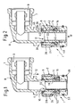
- a connector 1 consists in all embodiments of a housing part 2 with (at least) a plug-in receptacle 4 (see in particular Fig. 5 to 7 ) for the axial, media-tight insertion of a pipe piece-shaped insertion part 6 (see the separate illustration in FIG Fig. 4 ).
- the male member 6 is formed as a portion of a connector piece 8, which - as shown - can be configured for example as an angle connector.
- the connector piece 8 may have on its side opposite the male part 6 a connecting portion 7, which may be formed analogous to the connector 1 and the housing part 2 as a similar plug-in receptacle 9.
- the connector piece 8 is formed by a one-piece plastic molding. Basically, the connector 1 but also for the direct connection of Suitable piping, in which case the male member 6 is formed by one end of the pipe (not shown).
- a holding element 14 for locking the inserted plug-in part 6 and a media seal 16 are arranged in an adjoining region.
- the dirt seal 10 and the media seal 16 come directly to the peripheral system on the outer circumference of the inserted plug 6 (see Fig. 3 ).
- the holding element 14 is preferably designed as a slotted and thus radially elastic clamping ring which cooperates with an inner cone 18 in the socket 4 for locking the male member 6 so that it by a movement opposite to the insertion 12 via the inner cone 18 radially inwardly to clamped holder of the male part 6 is deformed (narrowed).
- a coaxial to the insertion axis support sleeve 22 is arranged for non-positive, play-free engagement in the inserted plug 6 within the housing part.
- the support sleeve 22 thus supports the plugged insertion part 6, on the one hand, against the radial force applied via the holding element 14 and, on the other hand, radially against the contact force of the media seal 16 from the inside.
- the connector 1 is basically suitable for hose lines.
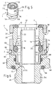
- the housing part 2 is in two parts from a base part 24 and one with this over a Snap-fit form-locking connection 26 (positive locking connection with an effective undercutting angle greater than / equal to 90 °, see in particular Fig. 5 to 7 ), the inner cone 18 having insert part 28 is formed.
- the insert member 28 the dirt seal 10 for circumferentially bearing on the inserted plug 6.
- the insert member 28 is formed together with the dirt seal 10 as one-piece two-component molding of two different plastic materials, and that is the insert member 28 of a first, relatively harder and dimensionally stable plastic, while the dirt seal 10 directly integrally materially from a second, relatively softer and elastic plastic is molded.
- the dirt seal 10 see in particular Fig. 6 and 7 , On its radially inwardly facing side of a bead-like sealing area for circumferentially bearing on the male part 6 on.
- the insert member 28 is generally formed together with the dirt seal 10 substantially sleeve-shaped and inserted into an extension of the plug receptacle 4 of the base member 24 preferably with a press fit and thereby at least against the ingress of dirt and the like foreign matter sealing or usable. It is advantageous if the insert part 28 in the inserted state is completely flush with the mouth side within the base part 24. This results in a compact design of the connector 1, the mouth side has a flat, on the dirt seal 10 to the plug 6 towards closed end face.
- the snap-fit form-fitting connection 26 may be a circumferentially circumferential, closed embodiment of latching elements (not shown), which, because of the achieved positive connection, leads to an insolubility of the plug-in part 6.
- the sleeve-shaped insert member 28 has at least two radially elastic spring arms formed by longitudinal slots (not visible in the drawings). Each spring arm engages with a radially outwardly projecting, nose-like locking projection 32 positively, ie with undercut greater than / equal to 90 °, in a corresponding detent opening 34 of the Base part 24 releasably (see Fig. 5 to 7 ).
- the latching openings 34 are formed as radial passage openings, so that the locking lugs 32 can be achieved for releasing from the outside with a suitable tool and can be moved radially inward, whereby the male member 6 can be removed together with the holding member 14 and the insert member 28.
- the plug connector 1 operates according to the plug-in principle "holding before sealing", because the plug-in part 6 first passes into the region of the holding element 14 and only then into the area of the media seal 16 , As a result, the insertion part 6 can already be locked against loosening via the retaining element 14 before the connection is sealed off via the media seal 16. For this reason, a leakage path is formed such that in its such, locked by the retaining element 14, but not yet sealed over the media seal 16 Vorarretier ein the male part 6 a defined limited, physically perceptible leak is ensured. This is in Fig. 2 indicated by arrows 36.
- the leakage path is formed by depressions 40 arranged on the outer circumference 38 of the insertion part 6 and / or the cylindrical outer periphery 38, see in particular Fig. 4 ,
- These recesses 40 are in the Vorarretier ein ( Fig. 2 ) on the one hand in the region of the media seal 16 and on the other hand in the region of the dirt seal 10.
- pressure p pressurization
- pressure p can thus escape over the leakage path formed by the wells 40 and thus to the seals 16, 10 over the respective medium in the direction of arrow 36, which is noticeable by a noise (hiss, whistle).
- the recesses 40 are preferably arranged in two groups each having a plurality of radially symmetrically distributed over the circumference and arranged axially spaced over a cylindrical media sealing portion 42 wells 40.
- Each group of depressions 40 consists in particular of approximately ten to fifteen, preferably for example twelve depressions 40.
- An indentation cylindrical on the side opposite the media-sealing section 42 adjoins the depressions 40 which are remote from a front insertion end 44 of the insertion part 6 Dirt seal section 46 at.
- the depressions 40 associated with the media seal 16 preferably start from the front insertion end 44 of the insertion part 6.
- All recesses 40 preferably each have an elongated, in particular approximately rectangular, shape aligned in the insertion direction 12. According to 3 and 4 corresponds to the axial center distance A of the recesses 40 of the two groups at least approximately the axial distance B between the media seal 16 and dirt seal 10th
- the connector 1 can be a direct component of any unit part, for example a valve block.
- the housing part 2 via (at least) a connecting portion 48 with another arbitrary aggregate part (not shown) connectable.
- the housing part 2 is formed as a press-fit, wherein the insertion portion formed as a connecting portion 48 can be inserted (press-fitted) into a connection opening of an aggregate part, not shown.
- the connection opening can be a simple, smooth-walled bore, for which purpose the connecting section 48 has tooth-like holding elements 50 and at least one sealing ring 52.
- the connecting portion 48 is formed as a screw threaded connector 54.
- an additional sealing ring 56 is provided in particular as an axial seal and for torque introduction when screwing the ffergewindestutzen 54 an external hex 58th
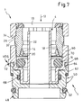
- the base member 24 is again in two parts from a receiving part 60 for the support member 14, the media seal 16 and for the insert member 28 and a connector 62 for connection of the housing part 2.
- the connecting part 62 on the above-mentioned connecting portion 48.
- the receiving part 60 can advantageously be connected to a variety of adapter-like connecting parts 62, each with the same configuration, so that a type of modular system is created.
- the connection area between receiving part 60 and connector 62 is always the same, whereas the Connection area may be performed with different connection portions 48; compare Fig. 6 and 7 ,
- the receiving part 60 and the connecting part 62 via a snap-fit positive connection 64 in particular permanently connected to each other.
- the positive connection 64 is formed with a circumferentially closed line profile.
- the parts 60, 62 are thereby assembled and locked in a simple manner, but not subsequently, at least not non-destructively separable.
- the parts in the connection area are designed so that their outer contours are axially aligned with one another via a gap 66. In its mated region, an annular gap between the receiving part 60 and the connecting part 62 is sealed media-tightly via a seal 68.
- the receiving part 60 is preferably made of plastic, while the connecting part 62 in particular made of metal, for example brass.
- the media seal 16 is arranged in an inner annular chamber 70, which is formed between the base part 24 or the receiving part 60 and the insert part 28.
- the above-mentioned support sleeve 22 may advantageously be formed integrally with the receiving part 60 ( Fig. 6 and 7 ). In the execution according to Fig. 1 to 3 the support sleeve 22 is inserted as a separate part in the base part 24.
- means for securing the male member 6 are provided against rotation about the thru-axle. These means for preventing rotation are designated in the drawing with VDS (see in particular the Fig. 3 . 6 and 7 ).
- This anti-rotation VDS is particularly important in Winket connectors of importance (Richtsein herekeit).
- the means for preventing rotation VDS are formed by positive-locking elements 72 such that the respective individual parts are mounted axially (can be plugged together), but positively secured against Relatiwerpitung.
- the plug-in part 6 or the connector piece 8 is connected via such form-locking elements 72 with the housing part 2, wherein it according to Fig.
- FIG. 3 can act with a hexagonal or Veliereeingriff a housing 2 cross-section of the male member 6.
- an anti-rotation by corresponding positive locking elements 72 may be provided in the two-part embodiment of the base part 24 according to Fig. 6 and 7 must also between the receiving part 60 and the Connecting part 62 an anti-rotation by corresponding positive locking elements 72 may be provided.
- they may be internal interlocking elements 72, which are arranged in an inner insertion region of the two parts 60, 62.
- Fig. 7 it is external overlapping positive locking elements 72.
- An external anti-rotation VDS can be reallsieren easier to manufacture.
- An internal VDS has the advantage of a very compact design without outside protruding parts.
- anti-rotation VDS must be provided in cooperation with the respective unit part, in particular in the region of the connecting portion 48.
Description
- Die vorliegende Erfindung betrifft einen Steckverbinder für Medienleitungen gemäß dem Oberbegriff des Anspruchs 1.
- Die
EP 0 733 844 B1 beschreibt eine solche Anschlußvorrichtung mit den Merkmalen des Oberbegriffs des Anspruchs 1. Die Zweiteiligkeit des Gehäuseteils ermöglicht eine einfache Montage und Demontage sowie ein Lösen des Einsteckteils. Das Einsatzteil besteht aus einem einstückigen Kunststoff-Formteil, wobei eine Schmutzdichtung, die ein Eindringen von Staub, Schmutz, Feuchtigkeit (Spritzwasser) und dergleichen verhindern soll, als umlaufende Dichtlippe einstückig angeformt ist. Zum Zwecke der Lösbarkeit des Einsteckteils weist dabei das Einsatzteil zwei elastische Rastarme auf, die mit Rastansätzen in das Basisteil und in dort gebildete Rastöffnungen eingreifen. Jeder Rastarm weist einen aus dem Basisteil nach außen vorstehenden Betätigungsabschnitt auf. - Die Veröffentlichung
US 2003/0178846 A1 beschreibt einen Leitungsverbinder, der aus einem rohrförmigen, gebogenen Verbindungskörper aus Kunststoff und einem Anschlussteil aus Metall besteht. Das Anschlussteil ist mit einem Steckabschnitt in den Verbindungskörper eingesteckt, wobei der Steckabschnitt auf seinem Außenumfang einen zahnartigen Ringvorsprung mit einem scharfen Querschnitt aufweist, der in die zylindrische Innenfläche des Verbindungskörpers eingreift bzw. einschneidet Auf der gegenüberliegenden Seite des Verbindungskörpers ist eine Steckaufnahme für eine Leitung gebildet, und innerhalb der Steckaufnahme sind ein Halteelement zum Arretieren sowie eine Mediendichtung zum Abdichten der Leitung angeordnet. Diese Teile werden durch ein eingesetztes, hülsenförmiges Führungsteil gehalten, wobei das Führungsteil - analog zu dem Anschlussteil - auf seinem Außenumfang einen scharfen, zahnförmigen Ringvorsprung aufweist, der in die zylindrische Innenfläche des Verbindungskörpers einschneidet. Somit handelt es sich bei den Verbindungen zwischen dem Anschlussteil und dem Verbindungskörper sowie auch zwischen dem Verbindungskörper und dem eingesetzten Führungsteil um unlösbare, aber gegeneinander verdrehbare Verbindungen. Um ein Lösen der eingesteckten Leitung zu ermöglichen, ist eine zusätzliche Lösehülse vorgesehen, die verschiebbar in die Steckaufnahme eingreift, um durch Einschieben das Halteelement zwecks Freigabe der Leitung zu betätigen. - Der vorliegenden Erfindung liegt die Aufgabe zugrunde, einen Steckverbinder der genannten Art weiter zu verbessern und zu vereinfachen.
- Erfindungsgemäß wird dies durch die Merkmale des unabhängigen Patentanspruchs 1 erreicht. Vorteilhafte Ausgestaltungsmerkmale der Erfindung sind in den abhängigen Ansprüchen enthalten.
- Demnach ist erfindungsgemäß das Basisteil seinerseits ebenfalls zweiteilig aus einem Aufnahmeteil für das Halteelement, die Mediendichtung und das Einsatzteil sowie aus einem Anschlussteil zur Anschlussverbindung des Gehäuseteils an einer Medienleitung ausgebildet, wobei vorteilhafterweise zwischen dem Aufnahmeteil und dem Anschlussteil Mittel zur Sicherung gegen relatives Verdrehen vorgesehen sind. Vorzugsweise sind Mittel zur Sicherung des gesamten eingesteckten Einsteckteils gegen Verdrehen um die Steckachse relativ zu dem erfindungsgemäßen Steckverbinder vorgesehen. Die Mittel zur Verdrehsicherung sind hierbei von Formschlusselementen derart gebildet, dass die Einzelteile axial montierbar, aber gegen Relatiwerdrehung gesichert sind. Durch die erfindungsgemäße Ausgestaltung eignet sich der Steckverbinder auch für Winkelverbinder, bei denen es auf eine Richtungseinstellbarkeit ankommt.
- In einer bevorzugten Ausgestaltung der Erfindung ist vorgesehen, dass innerhalb der Steckaufnahme ausgehend von einer mündungsseitigen Schmutzdichtung in Einsteckrichtung gesehen zunächst das Halteelement zum Arretieren des eingesteckten Einsteckteils und daran anschließend die Mediendichtung angeordnet sind, wobei ein Leckagepfad derart gebildet ist, dass in einer durch das Halteelement arretierten, aber noch nicht über die Mediendichtung abgedichteten Vorarretierstellung des Einsteckteils eine definiert begrenzte, physisch wahmehmbare Undichtigkeit gewährleistet ist. Dadurch soll eine nicht ganz gesteckte, zwar schon arretierte, aber noch nicht korrekt abgedichtete Stellung bemerkbar sein, indem über den Leckagepfad eine Undichtigkeit insbesondere akustisch durch eine Geräuschbildung wahrnehmbar ist. Es ist vorteilhaft, wenn der Leckagepfad durch auf dem Außenumfang des Einsteckteils angeordnete Vertiefungen gebildet ist, die in der Vorarretierstellung einerseits im Bereich der Mediendichtung und andererseits im Bereich der Schmutzdichtung angeordnet sind. Durch diese Ausgestaltung erübrigt sich zur Schaffung des Leckagepfades eine Öffnung des Gehäuseteils, und als Dichtungen (insbesondere für die Mediendichtung) können einfache und preisgünstige O-Ringe verwendet werden. Die Leckage erfolgt dann in der Vorarretierstellung über die jeweilige Vertiefung des Einsteckteils radial innen und axial an dem die Vertiefung überspannenden Dichtring vorbei. In der ganz gesteckten Vollsteckstellung liegen die Dichtungen dann in Umfangsrichtung vollständig auf zylindrischen Dichtabschnitten des Einsteckteils an. Es ergibt sich dadurch eine konstruktiv sehr einfache und kostengünstige Ausführung. Dabei ist das Einsteckteil bevorzugt als. Formteil aus Kunststoff ausgebildet. Dies ermöglicht eine einfache Einformung der Vertiefungen.
- Anhand von in der Zeichnung veranschaulichten, bevorzugten Ausführungsbeispielen soll die Erfindung genauer erläutert werden. Dabei zeigen:
- Fig. 1
- einen Längsschnitt durh eine nicht erfindungsgemäße Ansführung eines Steckverbinders mit Einsteckteil während des Einsteckvorgangs, d. h. in einer noch nicht ganz eingesteckten Stellung,
- Fig. 2
- eine Darstellung analog zu
Fig. 1 mit dem in einer Vorarretierstellung befindlichen Elnstecktell unter Druckbeaufschlagung zur Erläuterung des Leckagepfades, - Fig. 3
- eine weitere Darstellung analog zu
Fig. 1 bzw. 2 einer Ausführungsvariante mit Verdrehsicherung des Einsteckteils in der ganz gesteckten und abgedichteten Vollsteckstellung, - Fig. 4
- eine Seitenansicht nur des Einsteckteils der Ausführung gemäß
Fig. 1 bis 3 , - Fig. 5
- eine Perspektivansicht einer Ausführungsform eines erfindungsgemäßen Steckverbinders (ohne Einstecktell),
- Fig. 6
- eine vergrößerte Längsschnittdarstellung des erfindungsgemäßen Steckverbinders gemäß
Fig. 5 und - Fig. 7
- eine Darstellung analog zu
Fig. 6 in einer Ausführungsvariante des erfindungsgemäßen Steckverbinders. - In den verschiedenen Figuren der Zeichnung sind gleiche Teile stets mit den gleichen Bezugszeichen versehen. Daher gilt jede Beschreibung eines Teils unter Bezugnahme auf eine bestimmte Zeichnungsfigur analog auch für alle anderen Zeichnungsfiguren, in denen das besagte Teil mit dem entsprechenden Bezugszeichen ebenfalls zu erkennen ist. Es sei bemerkt, dass nur die
Figuren 5 bis 7 dem Anspruch 1 entsprechen, während dieFiguren 1 bis 4 nur Teilmerkmale der Erfindung zeigen. - Ein Steckverbinder 1 besteht in allen Ausführungsbeispielen aus einem Gehäuseteil 2 mit (mindestens) einer Steckaufnahme 4 (siehe insbesondere
Fig. 5 bis 7 ) zum axialen, mediendichten Einstecken eines rohrstückförmlgen Einsteckteils 6 (siehe hierzu die gesonderte Darstellung inFig. 4 ). Bei diesem Beispiel ist das Einsteckteil 6 als Abschnitt eines Verbinderstückes 8 ausgebildet, welches - wie dargestellt - beispielsweise als Winkelverbinder ausgeführt sein kann. Das Verbinderstück 8 kann auf seiner dem Einsteckteil 6 gegenüberliegenden Seite einen Verbindungsabschnitt 7 aufweisen, der analog zu dem Steckverbinder 1 bzw. dem Gehäuseteil 2 als gleichartige Steckaufnahme 9 ausgebildet sein kann. Bevorzugt wird das Verbinderstück 8 von einem einstückigen Formteil aus Kunststoff gebildet. Grundsätzlich ist der Steckverbinder 1 jedoch auch zum direkten Anschluß von Rohrleitungen geeignet, wobei dann das Einsteckteil 6 von einem Ende der Rohrleitung gebildet ist (nicht dargestellt). - Innerhalb der Steckaufnahme 4 sind ausgehend von einer mündungsseitigen Schmutzdichtung 10 in Einsteckrichtung (Pfeil 12) gesehen zunächst ein Halteelement 14 zum Arretieren des eingesteckten Einsteckteils 6 und in einem sich daran anschließenden Bereich eine Mediendichtung 16 (Druckdichtung) angeordnet. Die Schmutzdichtung 10 und die Mediendichtung 16 kommen unmittelbar zur umfangsgemäßen Anlage auf dem Außenumfang des eingesteckten Einsteckteils 6 (siehe
Fig. 3 ). Das Halteelement 14 ist bevorzugt als geschlitzter und dadurch radial elastischer Klemmring ausgebildet, der zum Arretieren des Einsteckteils 6 so mit einem Innenkonus 18 in der Steckaufnahme 4 zusammenwirkt, dass er durch eine Bewegung entgegen der Einsteckrichtung 12 über den Innenkonus 18 radial nach innen zur klemmenden Halterung des Einsteckteils 6 verformt (verengt) wird. Dabei wirkt er mit mindestens einer radial nach innen ragenden, umlaufenden Zahnkante 20 gegen den Außenumgang des Einsteckteils 6. Dazu wird insbesondere auf die vergrößerte Darstellung inFig. 6 verwiesen. Durch diese Ausgestaltung wird durch eine Bewegung des zuvor eingesteckten Einsteckteils 6 zurück in Löserichtung das Halteelement 14 bzw. der Klemmring zunächst durch kraftschlüssige Anlage seiner Zahnkante 20 mitgenommen, bis er mit seinem Außenkonus zur Anlage in dem Innenkonus 18 des Gehäuseteils 2 gelangt. Bei weitergehendem Zug wird über die Konen eine radial nach innen gerichtete Kraft erzeugt, durch die der Klemmring elastisch verengt wird, so dass die Zahnkante 20 kraft- und/oder formschlüssig mit dem im Wesentlichen glattflächigen, zylindrischen Außenumfang des Einsteckteils 6 zusammenwirkt und dieses so gegen Herausziehen arretiert wird. - In weiterer bevorzugter Ausgestaltung ist innerhalb des Gehäuseteils 2 eine zur Steckachse koaxiale Stützhülse 22 zum kraftschlüssigen, spielfreien Eingriff in das eingesteckte Einsteckteil 6 angeordnet. Die Stützhülse 22 stützt somit das aufgesteckte Einsteckteil 6 einerseits gegen die über das Halteelement 14 aufgebrachte Radialkraft und andererseits auch gegen die Anlagekraft der Mediendichtung 16 von innen her radial ab. Dadurch ist der Steckverbinder 1 grundsätzlich auch für Schlauchleitungen geeignet.
- Zum Zwecke der Herstellbarkeit bzw. Montierbarkeit des Steckverbinders 1 ist das Gehäuseteil 2 zweiteilig aus einem Basisteil 24 und einem mit diesem über eine schnappbare Formschlußverbindung 26 (formschlüssige Rastverbindung mit einem Wirkflächen-Hinterschneidungswinkel größer/gleich 90°; siehe dazu insbesondere
Fig. 5 bis 7 ) verbundenen, den Innenkonus 18 aufweisenden Einsatzteil 28 ausgebildet. Dabei weist das Einsatzteil 28 die Schmutzdichtung 10 zur umfangsgemäßen Anlage auf dem eingesteckten Einsteckteil 6 auf. - Das Einsatzteil 28 ist gemeinsam mit der Schmutzdichtung 10 als einstückiges Zweikomponenten-Formteil aus zwei unterschiedlichen Kunststoff-Materialien ausgebildet, und zwar besteht das Einsatzteil 28 aus einem ersten, relativ härteren und formstabilen Kunststoff, während die Schmutzdichtung 10 unmittelbar einstückig materialschlüssig aus einem zweiten, relativ weicheren und elastischen Kunststoff angeformt ist. Hierbei weist die Schmutzdichtung 10, siehe dazu insbesondere
Fig. 6 und7 , auf ihrer radial nach innen weisenden Seite einen wulstartigen Dichtungsbereich zur umfangsgemäßen Auflage auf dem Einsteckteil 6 auf. - Das Einsatzteil 28 ist gemeinsam mit der Schmutzdichtung 10 insgesamt im Wesentlichen hülsenförmig ausgebildet und in eine Erweiterung der Steckaufnahme 4 des Basisteils 24 vorzugsweise mit Presspassung und dadurch zumindest gegen Eindringen von Schmutz und dergleichen Fremdstoffen dichtend eingesetzt bzw. einsetzbar. Es ist vorteilhaft, wenn das Einsatzteil 28 im eingesetzten Zustand mündungsseitig bündig abschließend vollständig innerhalb des Basisteils 24 liegt. Daraus resultiert eine kompakte Bauform des Steckverbinders 1, der mündungsseitig eine ebene, über die Schmutzdichtung 10 zum Einsteckteil 6 hin geschlossene Stirnfläche aufweist.
- Bei der schnappbaren Formschlußverbindung 26 kann es sich um eine in Umfangsrichtgung umlaufende, geschlossene Ausführung von Rastelementen handeln (nicht dargestellt), was wegen des erreichten Formschlusses zu einer Unlösbarkeit des Einsteckteils 6 führt.
- Im Gegensatz dazu ist allerdings bei den dargestellten Ausführungsformen zwecks Lösbarkeit des Einsteckteils 6 vorgesehen, dass das hülsenförmige Einsatzteil 28 mindestens zwei durch Längsschlitze gebildete, radialelastische Federarme aufweist (in den Zeichnungen nicht erkennbar). Jeder Federarm greift mit einem radial nach außen ragenden, nasenartigen Rastansatz 32 formschlüssig, d. h. mit Hinterschneidung größer/gleich 90°, in eine korrespondierende Rastöffnung 34 des Basisteils 24 lösbar ein (siehe
Fig. 5 bis 7 ). Die Rastöffnungen 34 sind als radiale Durchgangsöffnungen ausgebildet, so dass die Rastansätze 32 zum Lösen von außen mit einem geeigneten Werkzeug erreicht und radial nach innen bewegt werden können, wodurch das Einsteckteil 6 gemeinsam mit dem Halteelement 14 und dem Einsatzteil 28 entnommen werden kann. - Aufgrund der beschriebenen Ausgestaltung und Anordnung des Halteelementes 14 und der Mediendichtung 16 arbeitet der erfindungsgemäße Steckverbinder 1 nach dem Steckprinzip "Halten vor Dichten", weil das Einsteckteil 6 beim Einstecken zunächst in den Bereich des Halteelementes 14 und erst danach in den Bereich der Mediendichtung 16 gelangt. Dadurch kann das Einsteckteil 6 bereits über das Halteelement 14 gegen Lösen arretiert werden, bevor die Verbindung über die Mediendichtung 16 abgedichtet ist. Aus diesem Grund ist ein Leckagepfad derart gebildet, dass in seiner solchen, durch das Halteelement 14 arretierten, aber noch nicht über die Mediendichtung 16 abgedichteten Vorarretierstellung des Einsteckteils 6 eine definiert begrenzte, physisch wahrnehmbare Undichtigkeit gewährleistet ist. Dies ist in
Fig. 2 durch Pfeile 36 angedeutet. - Gemäß
Fig. 1 bis 4 ist der Leckagepfad durch auf dem Außenumfang 38 des Einsteckteils 6 angeordnete bzw. den zylindrischen Außenumfang 38 unterbrechende Vertiefungen 40 gebildet, siehe dazu insbesondereFig. 4 . Diese Vertiefungen 40 sind in der Vorarretierstellung (Fig. 2 ) einerseits im Bereich der Mediendichtung 16 und andererseits im Bereich der Schmutzdichtung 10 angeordnet. Im Falle einer Druckbeaufschlagung (Druck p) kann somit über den von den Vertiefungen 40 gebildeten Leckagepfad und damit an den Dichtungen 16, 10 vorbei das jeweilige Medium in Pfeilrichtung 36 entweichen, was sich durch ein Geräusch (zischen, pfeifen) bemerkbar macht. - Wie sich weiterhin aus
Fig. 4 ergibt, sind die Vertiefungen 40 bevorzugt in zwei Gruppen zu je mehreren über den Umfang radialsymmetrisch verteilt angeordneten und axial über einen zylindrischen Mediendichtabschnitt 42 beabstandeten Vertiefungen 40 angeordnet. Jede Gruppe von Vertiefungen 40 besteht aus insbesondere etwa zehn bis fünfzehn, vorzugsweise z.B. zwölf Vertiefungen 40. An die von einem vorderen Einsteckende 44 des Einsteckteils 6 entfernt liegenden, der Schmutzdichtung 10 zugeordneten Vertiefungen 40 schließt sich auf der dem Mediendichtabschnitt 42 gegenüberliegenden Seite ein ebenfalls zylindrischer Schmutzdichtabschnitt 46 an. Die der Mediendichtung 16 zugeordneten Vertiefungen 40 gehen bevorzugt vom vorderen Einsteckende 44 des Einsteckteils 6 aus. Alle Vertiefungen 40 weisen bevorzugt jeweils eine in Einsteckrichtung 12 ausgerichtete längliche, insbesondere etwa rechteckige Form auf. GemäßFig. 3 und 4 entspricht der axiale Mittenabstand A der Vertiefungen 40 der beiden Gruppen zumindest annähernd dem axialen Abstand B zwischen Mediendichtung 16 und Schmutzdichtung 10. - Grundsätzlich kann der Steckverbinder 1 unmittelbarer Bestandteil eines beliebigen Aggregateteils, beispielsweise eines Ventilblocks, sein. In den dargestellten Ausführungen ist aber das Gehäuseteil 2 über (mindestens) einen Verbindungsabschnitt 48 mit einem weiteren beliebigen Aggregateteil (nicht dargestellt) verbindbar.
- Bei den Ausführungen gemäß
Fig. 1 bis 3 sowie 7 ist das Gehäuseteil 2 als Einpreßpatrone ausgebildet, wobei der als Einsteckabschnitt ausgebildete Verbindungsabschnitt 48 in eine Anschlußöffnung eines nicht dargestellten Aggregateteils einsetzbar (einpreßbar) ist. Bei der Anschlußöffnung kann es sich um eine einfache, glattwandige Bohrung handeln, wozu dann der Verbindungsabschnitt 48 zahnartige Halteelemente 50 sowie mindestens einen Dichtring 52 aufweist. Alternativ dazu ist bei der Ausführung gemäßFig. 6 vorgesehen, dass der Verbindungsabschnitt 48 als Schraubgewindestutzen 54 ausgebildet ist. Dabei ist ein zusätzlicher Dichtring 56 insbesondere als Axialdichtung vorgesehen sowie zur Drehmomenteinleitung beim Verschrauben des Schraubgewindestutzen 54 ein Außensechskant 58. - Bei den Ausführungen gemäß
Fig. 5 bis 7 ist dabei weiterhin erfindungsgemäß vorgesehen, dass das Basisteil 24 nochmals zweiteilig aus einem Aufnahmeteil 60 für das Halteelement 14, die Mediendichtung 16 und für das Einsatzteil 28 sowie aus einem Anschlußteil 62 zur Anschlußverbindung des Gehäuseteils 2 besteht. Dazu weist das Anschlußteil 62 den oben erwähnten Verbindungsabschnitt 48 auf. - Durch diese erfindungsgemäße Ausgestaltung kann vorteilhafterweise das Aufnahmeteil 60 mit einer stets gleichen Ausgestaltung wahlweise mit verschiedenen, adapterartigen Anschlußteilen 62 verbunden werden, so dass eine Art Baukastensystem geschaffen wird. Der Verbindungsbereich zwischen Aufnahmeteil 60 und Anschlußteil 62 ist dabei stets gleich ausgebildet, wohingegen der Anschlußbereich mit unterschiedlichen Verbindungsabschnitten 48 ausgeführt sein kann; vergleiche
Fig. 6 und7 . - Vorzugsweise sind das Aufnahmeteil 60 und das Anschlußteil 62 über eine schnappbare Formschlußverbindung 64 insbesondere unlösbar miteinander verbunden. Dazu ist die Formschlußverbindung 64 mit einem umfangsgemäß geschlossenen Linienverlauf ausgebildet. Die Teile 60, 62 sind dadurch auf einfache Weise zusammensteckbar und verrastbar, nachfolgend aber nicht, jedenfalls nicht zerstörungsfrei trennbar. Zweckmäßig sind die Teile im Verbindungsbereich so ausgeführt, dass ihre äußeren Konturen axial über einen Spalt 66 fluchtend ineinander übergehen. In ihrem zusammengesteckten Bereich ist ein Ringspalt zwischen dem Aufnahmeteil 60 und dem Anschlußteil 62 über eine Dichtung 68 mediendicht abgedichtet.
- Das Aufnahmeteil 60 besteht vorzugsweise aus Kunststoff, während das Anschlußteil 62 insbesondere aus Metall, beispielsweise Messing, besteht.
- Die Mediendichtung 16 ist in einer inneren Ringkammer 70 angeordnet, die zwischen dem Basisteil 24 bzw. dem Aufnahmeteil 60 und dem Einsatzteil 28 gebildet ist.
- Die oben erwähnte Stützhülse 22 kann mit Vorteil einstückig mit dem Aufnahmeteil 60 ausgebildet sein (
Fig. 6 und7 ). Bei der Ausführung gemäßFig. 1 bis 3 ist die Stützhülse 22 als separates Teil in das Basisteil 24 eingesetzt. - In weiterer Ausgestaltung der Erfindung sind Mittel zur Sicherung des Einsteckteils 6 gegen Verdrehen um die Steckachse vorgesehen. Diese Mittel zur Verdrehsicherung sind in der Zeichnung mit VDS bezeichnet (siehe hierzu insbesondere die
Fig. 3 ,6 und7 ). Diese Verdrehsicherung VDS ist insbesondere bei Winketverbindern von Bedeutung (Richtungseinstellbarkeit). Die Mittel zur Verdrehsicherung VDS sind von Formschlußelementen 72 derart gebildet, dass die jeweiligen Einzelteile axial montierbar (zusammensteckbar), aber gegen Relatiwerdrehung formschlüssig gesichert sind. Einerseits ist das Einsteckteil 6 bzw. das Verbinderstück 8 über solche Formschlußelemente 72 mit dem Gehäuseteil 2 verbunden, wobei es sich gemäßFig. 3 um einen das Gehäuse 2 übergreifenden Abschnitt des Einsteckteils 6 mit einem Sechskant- oder Velzahneingriff handeln kann. Bei der zweiteiligen Ausführung des Basisteils 24 gemäßFig. 6 und7 muß auch zwischen dem Aufnahmeteil 60 und dem Anschlußteil 62 eine Verdrehsicherung durch entsprechende Formschlußelemente 72 vorgesehen sein. GemäßFig. 6 kann es sich um innere Formschlußelemente 72 handeln, die in einem inneren Einsteckbereich der beiden Teile 60, 62 angeordnet sind. GemäßFig. 7 handelt es sich um äußere übergreifende Formschlußelemente 72. Eine außenliegende Verdrehsicherung VDS läßt sich fertigungstechnisch leichter reallsieren. Eine innenliegenden VDS hat den Vorteil einer sehr kompakten Bauweise ohne außen überstehende Teile. Bei der Ausführung des Gehäuses 2 als Einpreßpatrone (Fig. 1 bis 3 und7 ) muß zusätzlich eine weitere, nicht dargestellte Verdrehsicherung VDS im Zusammenwirken mit dem jeweiligen Aggregateteil, insbesondere im Bereich des Verbindungsabschnittes 48 vorgesehen sein.
Claims (16)
- Steckverbinder (1) für Medienleitungen,
bestehend aus einem Gehäuseteil (2) mit einer Steckaufnahme (4) zum mediendichten Einstecken eines rohrstückförmigen Einsteckteils (6), wobei in der Steckaufnahme (4) ein Halteelement (14) zum Arretieren sowie eine Mediendichtung (16) zum Abdichten des eingesteckten Einsteckteils (6) angeordnet sind, und wobei das Gehäuseteil (2) zum Zwecke der Montage und Demontage des Halte-elementes (14) und der Mediendichtung (16) sowie zum Lösen des Einsteckteils (6) zweiteilig aus einem Basisteil (24) und einem mit diesem über eine schnappbare Formschlußverbindung (26) lösbar verbundenen Einsatzteil (28) besteht,
dadurch gekennzeichnet, dass das Basisteil (24) seinerseits ebenfalls zweiteilig aus einem Aufnahmeteil (60) für das Halteelement (14) , die Mediendichtung (16) und das Einsatzteil (28) sowie aus einem Anschlußteil (62) zur Anschlußverbindung des Gehäuseteils (2) an eine Medienleitung besteht, wobei das Aufnahmeteil (60) und das Anschlussteil (62) aus unterschiedlichen Materialien bestehen und zwischen dem Aufnahmetell (60) und dem Anschlussteil (62) Mittel (VDS) zur Sicherung gegen relatives Verdrehen vorgesehen sind. - Steckverbinder nach Anspruch 1 mit einem eingesteckten Einsteckteil (6),
gekennzeichnet durch Mittel (VDS) zur Sicherung des eingesteckten Einsteckteils (6) gegen Verdrehen um die Steckachse. - Steckverbinder nach Anspruch 1 oder 2,
dadurch gekennzeichnet, dass die Mittel zur Verdrehsicherung (VDS) von Formschlußelementen (72) derart gebildet sind, dass die Einzelteile axial montierbar, aber gegen Relatiwerdrehung gesichert sind. - Steckverbinder nach einem der Ansprüche 1 bis 3,
dadurch gekennzeichnet, dass das Aufnahmeteil (60) und das Anschlußteil (62) über eine - insbesondere umfangsgemäß geschlossene - schnappbare Formschlußverbindung (64) miteinander verbunden sind. - Steckverbinder nach einem der Ansprüche 1 bis 4,
dadurch gekennzeichnet, dass ein Ringspalt (66) zwischen dem Aufnahmeteil (60) und dem Anschlußteil (62) über eine Dichtung (68) mediendicht abgedichtet ist. - Steckverbinder nach einem der Ansprüche 1 bis 5,
dadurch gekennzeichnet, dass das Aufnahmeteil (60) mit einer stets gleichen Ausgestaltung wahlweise mit verschiedenen, adapterartigen Anschlußteilen (62) verbindbar ist. - Steckverbinder nach einem der Ansprüche 1 bis 6,
dadurch gekennzeichnet, dass das Aufnahmeteil (60) aus Kunststoff und das Anschlußteil (62) insbesondere aus Metall bestehen. - Steckverbinder nach einem der Ansprüche 1 bis 7,
dadurch gekennzeichnet, dass das Halteelement (14) als geschlitzter, radialelastischer Klemmring ausgebildet ist, der zum Arretieren des Einsteckteils (6) mit einem Innenkonus (18) in der Steckaufnahme (4) zusammenwirkt, wobei der Innenkonus (18) in dem Einsatzteil (28) gebildet ist. - Steckverbinder nach einem der Ansprüche 1 bis 8,
dadurch gekennzeichnet, dass die Mediendichtung (16) in einer Ringkammer (70) zwischen dem Basisteil (24) bzw. dem Aufnahmeteil (60) und dem Einsatzteil (28) angeordnet ist. - Steckverbinder nach einem der Ansprüche 1 bis 9 mit einem eigesteckten Einsteckteil (6),
dadurch gekennzeichnet, dass innerhalb der Steckaufnahme (4) ausgehend von einer mündungsseitigen Schmutzdichtung (10) in Einsteckrichtung (12) gesehen zunächst das Halteelement (14) zum Arretieren des eingesteckten Einsteckteil (6) und daran anschließend die Mediendichtung (16) angeordnet sind, wobei ein Leckagepfad derart gebildet ist, dass in einer durch das Halteelement (14) arretierten, aber noch nicht über die Mediendichtung (16) abgedichteten Vorarretierstellung des Einsteckteils (6) eine definiert begrenzte, physisch wahmehmbare Undichtigkeit gewährleistet ist. - Steckverbinder mit dem eingesteckten Einsteckteil (6) nach Anspruch 10,
dadurch gekennzeichnet, dass der Leckagepfad durch auf dem Außenumfang (38) des Einsteckteils (6) angeordnete Vertiefungen (40) gebildet ist, die in der Vorarretlerstellung einerseits im Bereich der Mediendichtung (16) und andererseits im Bereich der Schmutzdichtung (10) angeordnet sind. - Steckverbinder mit dem eingesteckten Einsteckteil (6) nach Anspruch 11,
dadurch gekennzeichnet, dass die Vertiefungen (40) in zwei Gruppen zu je mehreren, über den Umfang verteilt angeordnet und axial über einen zylindrischen Mediendichtabschnitt (42) beabstandeten Vertiefungen (40) angeordnet sind. - Steckverbinder mit dem eingesteckten Einsteckteil (6) nach Anspruch 12,
dadurch gekennzeichnet, dass sich an die von einem vorderen Einsteckende (44) des Einsteckteils (6) entfernt liegenden, der Schmutzdichtung (10) zugeordneten Vertiefungen (40) auf der dem Mediendichtabschnitt (42) gegenüberliegenden Seite ein zylindrischer Schmutzdichtabschnitt (46) anschließt. - Steckverbinder mit dem eingesteckten Einsteckteil (6) nach einem der Ansprüche 11 bis 13,
dadurch gekennzeichnet, dass die der Mediendichtung (16) zugeordneten Vertiefungen (40) vom vorderen Einsteckende (44) des Einsteckteils (6) ausgehen. - Steckverbinder mit dem eingesteckten Einsteckteil (6) nach einem der Ansprüche 11 bis 14,
dadurch gekennzeichnet, dass die Vertiefungen (40) jeweils eine in Einsteckrichtung (12) ausgerichtete längliche, insbesondere etwa rechteckige Form aufweisen. - Steckverbinder mit dem eingesteckten Einsteckteil (6) nach einem der Ansprüche 11 bis 15,
dadurch gekennzeichnet, dass der axiale Mittenabstand (A) der Vertiefungen (40) dem axialen Abstand (B) zwischen Mediendichtung (16) und Schmutzdichtung (10) zumindest annähemd entspricht.
Applications Claiming Priority (2)
| Application Number | Priority Date | Filing Date | Title |
|---|---|---|---|
| DE20319959U DE20319959U1 (de) | 2003-12-23 | 2003-12-23 | Steckverbinder für Medienleitungen |
| PCT/EP2004/053588 WO2005064222A1 (de) | 2003-12-23 | 2004-12-17 | Steckverbinder für medienleitungen |
Publications (2)
| Publication Number | Publication Date |
|---|---|
| EP1697675A1 EP1697675A1 (de) | 2006-09-06 |
| EP1697675B1 true EP1697675B1 (de) | 2011-02-16 |
Family
ID=34559845
Family Applications (2)
| Application Number | Title | Priority Date | Filing Date |
|---|---|---|---|
| EP04804924A Not-in-force EP1697674B1 (de) | 2003-12-23 | 2004-12-17 | Steckverbinder für medienleitungen |
| EP04804926A Not-in-force EP1697675B1 (de) | 2003-12-23 | 2004-12-17 | Steckverbinder für medienleitungen |
Family Applications Before (1)
| Application Number | Title | Priority Date | Filing Date |
|---|---|---|---|
| EP04804924A Not-in-force EP1697674B1 (de) | 2003-12-23 | 2004-12-17 | Steckverbinder für medienleitungen |
Country Status (6)
| Country | Link |
|---|---|
| US (1) | US7922215B2 (de) |
| EP (2) | EP1697674B1 (de) |
| CN (1) | CN1918421B (de) |
| AT (2) | ATE498797T1 (de) |
| DE (3) | DE20319959U1 (de) |
| WO (2) | WO2005064222A1 (de) |
Cited By (2)
| Publication number | Priority date | Publication date | Assignee | Title |
|---|---|---|---|---|
| DE102012108759A1 (de) | 2012-06-26 | 2014-01-02 | Voss Automotive Gmbh | Anschlussvorrichtung für Medienleitungen |
| DE102017118393A1 (de) * | 2017-08-11 | 2019-02-14 | Voss Automotive Gmbh | Anschlussvorrichtung für Rohrleitungen mit Leckageanzeige |
Families Citing this family (35)
| Publication number | Priority date | Publication date | Assignee | Title |
|---|---|---|---|---|
| US7448653B2 (en) | 2005-06-10 | 2008-11-11 | Value Plastics, Inc. | Female connector for releasable coupling with a male connector defining a fluid conduit |
| DE202005013691U1 (de) | 2005-08-30 | 2007-01-11 | Voss Automotive Gmbh | Anschlussvorrichtung für Medienleitungen |
| US7806139B2 (en) | 2006-01-20 | 2010-10-05 | Value Plastics, Inc. | Fluid conduit coupling assembly having male and female couplers with integral valves |
| DE202006006301U1 (de) | 2006-04-18 | 2007-08-30 | Voss Automotive Gmbh | Steckverbinder für insbesondere aus Kunststoff bestehende Rohrleitungen |
| DE202006006304U1 (de) | 2006-04-18 | 2007-08-30 | Voss Automotive Gmbh | Steckverbinder für insbesondere aus Kunststoff bestehende Rohrleitungen |
| US7908730B2 (en) * | 2006-07-11 | 2011-03-22 | Haldex Brake Corporation | PTC fitting cartridge |
| USD654573S1 (en) | 2007-11-19 | 2012-02-21 | Value Plastics, Inc. | Female quick connect fitting |
| WO2009068934A1 (en) | 2007-11-28 | 2009-06-04 | Kongsberg Automotive As | Tube coupling system for a pressurised fluid system |
| US8235426B2 (en) | 2008-07-03 | 2012-08-07 | Nordson Corporation | Latch assembly for joining two conduits |
| FR2934029B1 (fr) * | 2008-07-16 | 2010-08-13 | Contitech Anoflex Sas | Raccord enfichable pour tuyau |
| USD655393S1 (en) | 2009-06-23 | 2012-03-06 | Value Plastics, Inc. | Multi-port valve |
| USD783815S1 (en) | 2009-12-09 | 2017-04-11 | General Electric Company | Male dual lumen bayonet connector |
| USD650478S1 (en) | 2009-12-23 | 2011-12-13 | Value Plastics, Inc. | Female dual lumen connector |
| US9388929B2 (en) | 2009-12-09 | 2016-07-12 | Nordson Corporation | Male bayonet connector |
| US10711930B2 (en) | 2009-12-09 | 2020-07-14 | Nordson Corporation | Releasable connection assembly |
| USD649240S1 (en) | 2009-12-09 | 2011-11-22 | Value Plastics, Inc. | Male dual lumen bayonet connector |
| JP5714028B2 (ja) | 2009-12-23 | 2015-05-07 | ノードソン コーポレーションNordson Corporation | 外形引込み部を有する流体コネクターラッチ |
| CN102753876B (zh) | 2009-12-23 | 2015-07-22 | 诺信公司 | 具有一体式模制悬臂弹簧的按钮闩 |
| USD652510S1 (en) | 2011-02-11 | 2012-01-17 | Value Plastics, Inc. | Connector for fluid tubing |
| USD663022S1 (en) | 2011-02-11 | 2012-07-03 | Nordson Corporation | Male body of connector for fluid tubing |
| USD652511S1 (en) | 2011-02-11 | 2012-01-17 | Value Plastics, Inc. | Female body of connector for fluid tubing |
| US8215962B1 (en) * | 2011-05-27 | 2012-07-10 | Manuel Machado | Waterproof swiveling electric cord slip coupling connector |
| USD699841S1 (en) | 2011-07-29 | 2014-02-18 | Nordson Corporation | Female body of connector for fluid tubing |
| USD699840S1 (en) | 2011-07-29 | 2014-02-18 | Nordson Corporation | Male body of connector for fluid tubing |
| USD698440S1 (en) | 2011-07-29 | 2014-01-28 | Nordson Corporation | Connector for fluid tubing |
| JP5081336B1 (ja) * | 2011-09-14 | 2012-11-28 | 株式会社オンダ製作所 | 継手及びそれに用いられるスペーサ |
| USD709612S1 (en) | 2011-12-23 | 2014-07-22 | Nordson Corporation | Female dual lumen connector |
| EP2630983B1 (de) * | 2012-02-22 | 2016-10-26 | ERBE Elektromedizin GmbH | Fluidkupplung mit mehreren radial beweglichen Steckelementen |
| US9145989B1 (en) | 2012-03-30 | 2015-09-29 | Dwayne Van Kooten | Sprinkler system coupler |
| GB201317990D0 (en) * | 2013-10-11 | 2013-11-27 | Guest John Int Ltd | A conncetor |
| US9890886B2 (en) | 2014-02-06 | 2018-02-13 | Miniature Precision Components, Inc. | Reverse snap push/pull quick connect coupling |
| USD838366S1 (en) | 2016-10-31 | 2019-01-15 | Nordson Corporation | Blood pressure connector |
| DE102018107505A1 (de) * | 2018-03-28 | 2019-10-02 | Voss Automotive Gmbh | "Anschlussvorrichtung für Medienleitungen" |
| DE102018122507A1 (de) * | 2018-09-14 | 2020-03-19 | Voss Automotive Gmbh | Anschlussvorrichtung für Rohrleitungen mit Leckageanzeige |
| KR102654568B1 (ko) * | 2018-10-01 | 2024-04-03 | 현대자동차주식회사 | 공압 회로용 커넥터 |
Family Cites Families (14)
| Publication number | Priority date | Publication date | Assignee | Title |
|---|---|---|---|---|
| US3649050A (en) * | 1970-06-15 | 1972-03-14 | George V Woodling | Tube fitting connection |
| US4201407A (en) * | 1978-10-23 | 1980-05-06 | Maremont Corporation | Tubular assembly |
| FR2479406B1 (fr) * | 1980-03-28 | 1985-08-23 | Legris | Raccords instantanes pour tubes nus et lisses |
| CN87205060U (zh) * | 1987-06-02 | 1988-03-16 | 四川省新津复合材料总厂 | 防腐蚀复合管管配件 |
| US4875709A (en) * | 1988-02-26 | 1989-10-24 | Caroll James E | Controlled leak path |
| US5403046A (en) * | 1994-05-12 | 1995-04-04 | Kooten; Dwayne V. | Elastomeric house coupling |
| US5468028A (en) * | 1994-12-19 | 1995-11-21 | Dana Corporation | Quick connect tube couplings |
| DE19510193A1 (de) * | 1995-03-21 | 1996-09-26 | Voss Armaturen | Anschlußvorrichtung für Rohrleitungen |
| DE19524934A1 (de) * | 1995-07-08 | 1997-01-09 | Voss Armaturen | Steckverbindung zum Anschluß von Druckmittelleitungen |
| JP3321061B2 (ja) * | 1997-12-19 | 2002-09-03 | 株式会社東郷製作所 | コネクタ |
| DE19803918B4 (de) * | 1998-02-02 | 2009-07-09 | Voss Automotive Gmbh | Anschlußvorrichtung für Rohrleitungen |
| NZ333076A (en) * | 1998-02-27 | 2000-06-23 | Guest John D | Tube coupling having a first and a second enlarged diameter portion and a plastics sleeve to seal a tube against the coupling |
| JP3372886B2 (ja) * | 1999-02-18 | 2003-02-04 | エスエムシー株式会社 | 管継手 |
| JP4288314B2 (ja) | 2002-03-22 | 2009-07-01 | Smc株式会社 | 管継手 |
-
2003
- 2003-12-23 DE DE20319959U patent/DE20319959U1/de not_active Expired - Lifetime
-
2004
- 2004-12-17 DE DE502004012211T patent/DE502004012211D1/de active Active
- 2004-12-17 AT AT04804926T patent/ATE498797T1/de active
- 2004-12-17 US US10/596,728 patent/US7922215B2/en not_active Expired - Fee Related
- 2004-12-17 CN CN2004800419908A patent/CN1918421B/zh not_active Expired - Fee Related
- 2004-12-17 EP EP04804924A patent/EP1697674B1/de not_active Not-in-force
- 2004-12-17 AT AT04804924T patent/ATE363047T1/de not_active IP Right Cessation
- 2004-12-17 WO PCT/EP2004/053588 patent/WO2005064222A1/de active Application Filing
- 2004-12-17 DE DE502004003915T patent/DE502004003915D1/de active Active
- 2004-12-17 WO PCT/EP2004/053586 patent/WO2005064221A1/de active IP Right Grant
- 2004-12-17 EP EP04804926A patent/EP1697675B1/de not_active Not-in-force
Cited By (4)
| Publication number | Priority date | Publication date | Assignee | Title |
|---|---|---|---|---|
| DE102012108759A1 (de) | 2012-06-26 | 2014-01-02 | Voss Automotive Gmbh | Anschlussvorrichtung für Medienleitungen |
| WO2014001144A1 (de) | 2012-06-26 | 2014-01-03 | Voss Automotive Gmbh | Anschlussvorrichtung für medienleitungen |
| DE102012108759B4 (de) * | 2012-06-26 | 2017-09-28 | Voss Automotive Gmbh | Anschlussvorrichtung für Medienleitungen |
| DE102017118393A1 (de) * | 2017-08-11 | 2019-02-14 | Voss Automotive Gmbh | Anschlussvorrichtung für Rohrleitungen mit Leckageanzeige |
Also Published As
| Publication number | Publication date |
|---|---|
| ATE363047T1 (de) | 2007-06-15 |
| DE502004003915D1 (de) | 2007-07-05 |
| EP1697675A1 (de) | 2006-09-06 |
| US20070284875A1 (en) | 2007-12-13 |
| DE502004012211D1 (de) | 2011-03-31 |
| CN1918421B (zh) | 2010-08-18 |
| ATE498797T1 (de) | 2011-03-15 |
| CN1918421A (zh) | 2007-02-21 |
| WO2005064222A1 (de) | 2005-07-14 |
| US7922215B2 (en) | 2011-04-12 |
| WO2005064221A1 (de) | 2005-07-14 |
| EP1697674B1 (de) | 2007-05-23 |
| EP1697674A1 (de) | 2006-09-06 |
| DE20319959U1 (de) | 2005-05-04 |
Similar Documents
| Publication | Publication Date | Title |
|---|---|---|
| EP1697675B1 (de) | Steckverbinder für medienleitungen | |
| EP1543267B1 (de) | Anschlussvorrichtung für rohrleitungen | |
| EP1920183B1 (de) | Anschlussvorrichtung für medienleitungen | |
| DE112006004024B4 (de) | Montagewerkzeug für eine Anschlussvorrichtung für Medienleitungen | |
| EP0816741A2 (de) | Einsteckkupplung | |
| EP3173675A1 (de) | Schlauchanschluss | |
| EP0579194A1 (de) | Steckarmatur zum schnellen und lösbaren Anschluss von Rohrleitungen | |
| EP3441657A1 (de) | Anschlussvorrichtung für rohrleitungen mit leckageanzeige | |
| EP2479470B1 (de) | Steckkupplung für Druckmittel-Leitungen | |
| WO2007118855A1 (de) | Steckverbinder für insbesondere aus kunststoff bestehende rohrleitungen | |
| EP0545037B1 (de) | Vorrichtung zum gegenseitigen Verbinden von zwei Leitungen, insbesondere Kraftstoffleitungen | |
| EP2008011B1 (de) | Steckverbinder für insbesondere aus kunststoff bestehende rohrleitungen | |
| DE102005044751B4 (de) | Steckverbinder für Medienleitungen | |
| EP1352193A1 (de) | Rast-steck-anschlusseinrichtung | |
| EP1770320B1 (de) | Lösbare Steckverbindung für Rohrleitungen | |
| DE19625687C2 (de) | Einsteckkupplung | |
| DE202008009398U1 (de) | Steckkupplung für Druckmittel-Leitungen | |
| EP0751332B1 (de) | Steckkupplung für Druckmittelsysteme | |
| EP2095003A1 (de) | Blockverbinder für fluidleitungen | |
| EP1936252A1 (de) | Anschlussvorrichtung für Medienleitungen | |
| DE102006026162B4 (de) | Anschlussvorrichtung für Medienleitungen | |
| DE10035791A1 (de) | Steckarmatur zum schnellen und lösbaren Anschluß von Druckmittel-Leitungen | |
| DE202004016097U1 (de) | Steckverbinder für Medienleitungen | |
| DE19513384B4 (de) | Steckkupplung für hydraulische Rohrleitungen | |
| DE10119585B4 (de) | Rohranschlußverbindung zum Steckanschluß eines Rohrendes |
Legal Events
| Date | Code | Title | Description |
|---|---|---|---|
| PUAI | Public reference made under article 153(3) epc to a published international application that has entered the european phase |
Free format text: ORIGINAL CODE: 0009012 |
|
| 17P | Request for examination filed |
Effective date: 20060623 |
|
| AK | Designated contracting states |
Kind code of ref document: A1 Designated state(s): AT BE BG CH CY CZ DE DK EE ES FI FR GB GR HU IE IS IT LI LT LU MC NL PL PT RO SE SI SK TR |
|
| 17Q | First examination report despatched |
Effective date: 20061011 |
|
| DAX | Request for extension of the european patent (deleted) | ||
| GRAP | Despatch of communication of intention to grant a patent |
Free format text: ORIGINAL CODE: EPIDOSNIGR1 |
|
| GRAC | Information related to communication of intention to grant a patent modified |
Free format text: ORIGINAL CODE: EPIDOSCIGR1 |
|
| GRAS | Grant fee paid |
Free format text: ORIGINAL CODE: EPIDOSNIGR3 |
|
| GRAA | (expected) grant |
Free format text: ORIGINAL CODE: 0009210 |
|
| AK | Designated contracting states |
Kind code of ref document: B1 Designated state(s): AT BE BG CH CY CZ DE DK EE ES FI FR GB GR HU IE IS IT LI LT LU MC NL PL PT RO SE SI SK TR |
|
| REG | Reference to a national code |
Ref country code: GB Ref legal event code: FG4D Free format text: NOT ENGLISH |
|
| REG | Reference to a national code |
Ref country code: CH Ref legal event code: EP |
|
| REG | Reference to a national code |
Ref country code: IE Ref legal event code: FG4D Free format text: LANGUAGE OF EP DOCUMENT: GERMAN |
|
| REF | Corresponds to: |
Ref document number: 502004012211 Country of ref document: DE Date of ref document: 20110331 Kind code of ref document: P |
|
| REG | Reference to a national code |
Ref country code: DE Ref legal event code: R096 Ref document number: 502004012211 Country of ref document: DE Effective date: 20110331 |
|
| REG | Reference to a national code |
Ref country code: SE Ref legal event code: TRGR |
|
| REG | Reference to a national code |
Ref country code: NL Ref legal event code: VDEP Effective date: 20110216 |
|
| LTIE | Lt: invalidation of european patent or patent extension |
Effective date: 20110216 |
|
| PG25 | Lapsed in a contracting state [announced via postgrant information from national office to epo] |
Ref country code: GR Free format text: LAPSE BECAUSE OF FAILURE TO SUBMIT A TRANSLATION OF THE DESCRIPTION OR TO PAY THE FEE WITHIN THE PRESCRIBED TIME-LIMIT Effective date: 20110517 Ref country code: PT Free format text: LAPSE BECAUSE OF FAILURE TO SUBMIT A TRANSLATION OF THE DESCRIPTION OR TO PAY THE FEE WITHIN THE PRESCRIBED TIME-LIMIT Effective date: 20110616 Ref country code: ES Free format text: LAPSE BECAUSE OF FAILURE TO SUBMIT A TRANSLATION OF THE DESCRIPTION OR TO PAY THE FEE WITHIN THE PRESCRIBED TIME-LIMIT Effective date: 20110527 Ref country code: LT Free format text: LAPSE BECAUSE OF FAILURE TO SUBMIT A TRANSLATION OF THE DESCRIPTION OR TO PAY THE FEE WITHIN THE PRESCRIBED TIME-LIMIT Effective date: 20110216 |
|
| PG25 | Lapsed in a contracting state [announced via postgrant information from national office to epo] |
Ref country code: SI Free format text: LAPSE BECAUSE OF FAILURE TO SUBMIT A TRANSLATION OF THE DESCRIPTION OR TO PAY THE FEE WITHIN THE PRESCRIBED TIME-LIMIT Effective date: 20110216 Ref country code: CY Free format text: LAPSE BECAUSE OF FAILURE TO SUBMIT A TRANSLATION OF THE DESCRIPTION OR TO PAY THE FEE WITHIN THE PRESCRIBED TIME-LIMIT Effective date: 20110216 Ref country code: PL Free format text: LAPSE BECAUSE OF FAILURE TO SUBMIT A TRANSLATION OF THE DESCRIPTION OR TO PAY THE FEE WITHIN THE PRESCRIBED TIME-LIMIT Effective date: 20110216 Ref country code: BG Free format text: LAPSE BECAUSE OF FAILURE TO SUBMIT A TRANSLATION OF THE DESCRIPTION OR TO PAY THE FEE WITHIN THE PRESCRIBED TIME-LIMIT Effective date: 20110516 Ref country code: FI Free format text: LAPSE BECAUSE OF FAILURE TO SUBMIT A TRANSLATION OF THE DESCRIPTION OR TO PAY THE FEE WITHIN THE PRESCRIBED TIME-LIMIT Effective date: 20110216 Ref country code: NL Free format text: LAPSE BECAUSE OF FAILURE TO SUBMIT A TRANSLATION OF THE DESCRIPTION OR TO PAY THE FEE WITHIN THE PRESCRIBED TIME-LIMIT Effective date: 20110216 |
|
| REG | Reference to a national code |
Ref country code: IE Ref legal event code: FD4D |
|
| PG25 | Lapsed in a contracting state [announced via postgrant information from national office to epo] |
Ref country code: EE Free format text: LAPSE BECAUSE OF FAILURE TO SUBMIT A TRANSLATION OF THE DESCRIPTION OR TO PAY THE FEE WITHIN THE PRESCRIBED TIME-LIMIT Effective date: 20110216 Ref country code: IE Free format text: LAPSE BECAUSE OF FAILURE TO SUBMIT A TRANSLATION OF THE DESCRIPTION OR TO PAY THE FEE WITHIN THE PRESCRIBED TIME-LIMIT Effective date: 20110216 Ref country code: DK Free format text: LAPSE BECAUSE OF FAILURE TO SUBMIT A TRANSLATION OF THE DESCRIPTION OR TO PAY THE FEE WITHIN THE PRESCRIBED TIME-LIMIT Effective date: 20110216 |
|
| PG25 | Lapsed in a contracting state [announced via postgrant information from national office to epo] |
Ref country code: CZ Free format text: LAPSE BECAUSE OF FAILURE TO SUBMIT A TRANSLATION OF THE DESCRIPTION OR TO PAY THE FEE WITHIN THE PRESCRIBED TIME-LIMIT Effective date: 20110216 Ref country code: RO Free format text: LAPSE BECAUSE OF FAILURE TO SUBMIT A TRANSLATION OF THE DESCRIPTION OR TO PAY THE FEE WITHIN THE PRESCRIBED TIME-LIMIT Effective date: 20110216 Ref country code: SK Free format text: LAPSE BECAUSE OF FAILURE TO SUBMIT A TRANSLATION OF THE DESCRIPTION OR TO PAY THE FEE WITHIN THE PRESCRIBED TIME-LIMIT Effective date: 20110216 |
|
| PLBE | No opposition filed within time limit |
Free format text: ORIGINAL CODE: 0009261 |
|
| STAA | Information on the status of an ep patent application or granted ep patent |
Free format text: STATUS: NO OPPOSITION FILED WITHIN TIME LIMIT |
|
| 26N | No opposition filed |
Effective date: 20111117 |
|
| REG | Reference to a national code |
Ref country code: DE Ref legal event code: R097 Ref document number: 502004012211 Country of ref document: DE Effective date: 20111117 |
|
| BERE | Be: lapsed |
Owner name: VOSS AUTOMOTIVE G.M.B.H. Effective date: 20111231 |
|
| PG25 | Lapsed in a contracting state [announced via postgrant information from national office to epo] |
Ref country code: MC Free format text: LAPSE BECAUSE OF NON-PAYMENT OF DUE FEES Effective date: 20111231 |
|
| REG | Reference to a national code |
Ref country code: CH Ref legal event code: PL |
|
| GBPC | Gb: european patent ceased through non-payment of renewal fee |
Effective date: 20111217 |
|
| REG | Reference to a national code |
Ref country code: FR Ref legal event code: ST Effective date: 20120831 |
|
| PG25 | Lapsed in a contracting state [announced via postgrant information from national office to epo] |
Ref country code: LI Free format text: LAPSE BECAUSE OF NON-PAYMENT OF DUE FEES Effective date: 20111231 Ref country code: CH Free format text: LAPSE BECAUSE OF NON-PAYMENT OF DUE FEES Effective date: 20111231 Ref country code: BE Free format text: LAPSE BECAUSE OF NON-PAYMENT OF DUE FEES Effective date: 20111231 Ref country code: GB Free format text: LAPSE BECAUSE OF NON-PAYMENT OF DUE FEES Effective date: 20111217 |
|
| REG | Reference to a national code |
Ref country code: AT Ref legal event code: MM01 Ref document number: 498797 Country of ref document: AT Kind code of ref document: T Effective date: 20111217 |
|
| PG25 | Lapsed in a contracting state [announced via postgrant information from national office to epo] |
Ref country code: FR Free format text: LAPSE BECAUSE OF NON-PAYMENT OF DUE FEES Effective date: 20120102 |
|
| PG25 | Lapsed in a contracting state [announced via postgrant information from national office to epo] |
Ref country code: LU Free format text: LAPSE BECAUSE OF NON-PAYMENT OF DUE FEES Effective date: 20111217 |
|
| PG25 | Lapsed in a contracting state [announced via postgrant information from national office to epo] |
Ref country code: AT Free format text: LAPSE BECAUSE OF NON-PAYMENT OF DUE FEES Effective date: 20111217 |
|
| PG25 | Lapsed in a contracting state [announced via postgrant information from national office to epo] |
Ref country code: IS Free format text: LAPSE BECAUSE OF FAILURE TO SUBMIT A TRANSLATION OF THE DESCRIPTION OR TO PAY THE FEE WITHIN THE PRESCRIBED TIME-LIMIT Effective date: 20110216 |
|
| PG25 | Lapsed in a contracting state [announced via postgrant information from national office to epo] |
Ref country code: TR Free format text: LAPSE BECAUSE OF FAILURE TO SUBMIT A TRANSLATION OF THE DESCRIPTION OR TO PAY THE FEE WITHIN THE PRESCRIBED TIME-LIMIT Effective date: 20110216 |
|
| PG25 | Lapsed in a contracting state [announced via postgrant information from national office to epo] |
Ref country code: HU Free format text: LAPSE BECAUSE OF FAILURE TO SUBMIT A TRANSLATION OF THE DESCRIPTION OR TO PAY THE FEE WITHIN THE PRESCRIBED TIME-LIMIT Effective date: 20110216 |
|
| PGFP | Annual fee paid to national office [announced via postgrant information from national office to epo] |
Ref country code: IT Payment date: 20181221 Year of fee payment: 15 |
|
| PGFP | Annual fee paid to national office [announced via postgrant information from national office to epo] |
Ref country code: SE Payment date: 20181228 Year of fee payment: 15 |
|
| PGFP | Annual fee paid to national office [announced via postgrant information from national office to epo] |
Ref country code: DE Payment date: 20191223 Year of fee payment: 16 |
|
| REG | Reference to a national code |
Ref country code: SE Ref legal event code: EUG |
|
| PG25 | Lapsed in a contracting state [announced via postgrant information from national office to epo] |
Ref country code: IT Free format text: LAPSE BECAUSE OF NON-PAYMENT OF DUE FEES Effective date: 20191217 Ref country code: SE Free format text: LAPSE BECAUSE OF NON-PAYMENT OF DUE FEES Effective date: 20191218 |
|
| REG | Reference to a national code |
Ref country code: DE Ref legal event code: R119 Ref document number: 502004012211 Country of ref document: DE |
|
| PG25 | Lapsed in a contracting state [announced via postgrant information from national office to epo] |
Ref country code: DE Free format text: LAPSE BECAUSE OF NON-PAYMENT OF DUE FEES Effective date: 20210701 |