EP1695155B1 - Herunterfahrvorrichtung und verfahren zur verwendung mit elektropneumatischen steuerungen - Google Patents
Herunterfahrvorrichtung und verfahren zur verwendung mit elektropneumatischen steuerungen Download PDFInfo
- Publication number
- EP1695155B1 EP1695155B1 EP20040795862 EP04795862A EP1695155B1 EP 1695155 B1 EP1695155 B1 EP 1695155B1 EP 20040795862 EP20040795862 EP 20040795862 EP 04795862 A EP04795862 A EP 04795862A EP 1695155 B1 EP1695155 B1 EP 1695155B1
- Authority
- EP
- European Patent Office
- Prior art keywords
- electro
- shut down
- signal
- pneumatic
- pneumatic controller
- Prior art date
- Legal status (The legal status is an assumption and is not a legal conclusion. Google has not performed a legal analysis and makes no representation as to the accuracy of the status listed.)
- Revoked
Links
Images

Classifications
-
- G—PHYSICS
- G05—CONTROLLING; REGULATING
- G05B—CONTROL OR REGULATING SYSTEMS IN GENERAL; FUNCTIONAL ELEMENTS OF SUCH SYSTEMS; MONITORING OR TESTING ARRANGEMENTS FOR SUCH SYSTEMS OR ELEMENTS
- G05B9/00—Safety arrangements
- G05B9/02—Safety arrangements electric
-
- Y—GENERAL TAGGING OF NEW TECHNOLOGICAL DEVELOPMENTS; GENERAL TAGGING OF CROSS-SECTIONAL TECHNOLOGIES SPANNING OVER SEVERAL SECTIONS OF THE IPC; TECHNICAL SUBJECTS COVERED BY FORMER USPC CROSS-REFERENCE ART COLLECTIONS [XRACs] AND DIGESTS
- Y10—TECHNICAL SUBJECTS COVERED BY FORMER USPC
- Y10T—TECHNICAL SUBJECTS COVERED BY FORMER US CLASSIFICATION
- Y10T137/00—Fluid handling
- Y10T137/0318—Processes
- Y10T137/0324—With control of flow by a condition or characteristic of a fluid
- Y10T137/0357—For producing uniform flow
Definitions
- the present invention relates generally to electro-pneumatic controllers and, more specifically, to a shut down apparatus and method that may be used with electro-pneumatic controllers.
- Process control plants or systems typically include numerous valves, pumps, dampers, boilers, as well many other types of well-known process control devices or operators.
- process control devices or operators In modem process control systems most, if not all, of the process control devices or operators are instrumented with electronic monitoring (e.g., temperature sensors, pressure sensors, position sensors, etc.) and electronic control devices (e.g., programmable controllers, analog control circuits, etc.) to coordinate the activities of the process control devices or operators to carry out one or more process control routines.
- electronic monitoring e.g., temperature sensors, pressure sensors, position sensors, etc.
- electronic control devices e.g., programmable controllers, analog control circuits, etc.
- process control devices are pneumatically actuated using well-known diaphragm type or piston type pneumatic actuators.
- pneumatic actuators are coupled to process control devices either directly or via one or more mechanical linkages.
- the pneumatic actuators are typically coupled to the overall process control system via an electro-pneumatic controller.
- Electro-pneumatic controllers are usually configured to receive one or more control signals (e.g., 4-20 milliamps (mA), 0-10 volts direct current (VDC), digital commands, etc.) and to convert these control signals into a pressure provided to the pneumatic actuator to cause a desired operation of the process control device.
- the magnitude of the control signal applied to an electro-pneumatic controller associated with the valve may be increased (e.g., from 10 mA to 15 mA in the case where the electro-pneumatic controller is configured to receive a 4-20 mA control signal).
- the output pressure provided by the electro-pneumatic controller to the pneumatic actuator coupled to the valve at least partially increases to stroke the valve toward a full open condition.
- safety is critically important.
- the leaking or other uncontrolled discharge of potentially toxic or flammable chemicals, gasses and the like presents significant risks for plant personnel and equipment.
- many industrial installations utilize safety shutdown systems in addition to the process control systems.
- These safety systems usually include valves and other control devices that have been configured to provide a shut down mode of operation (e.g., in an emergency situation) in which the process is forced to a known safe control condition.
- emergency shut down valves, emergency blow down valves, emergency venting valves, emergency isolation valves, critical on/off valves, etc. may be used to provide a desired level of safety within industrial process control plants.
- electro-pneumatic controllers used with many modem pneumatically actuated process control devices are often implemented using relatively complex digital control circuits.
- these digital control circuits may be implemented using a microcontroller, or any other type of processor, that executes machine readable instructions, code, firmware, software, etc. to control the operation of the process control device with which it is associated.
- some control equipment manufacturers recommend using a redundant instrument such as, for example, a solenoid actuated venting valve connected to the pressure output of the electro-pneumatic controller (i.e., the input of the pneumatic actuator coupled to the process control device).
- a redundant instrument such as, for example, a solenoid actuated venting valve connected to the pressure output of the electro-pneumatic controller (i.e., the input of the pneumatic actuator coupled to the process control device).
- a shut down signal may be applied (e.g., via the application or removal of power) to the solenoid of the venting valve, thereby venting the pneumatic actuator to atmosphere causing the actuator to drive the emergency shutdown device to a known safe condition (e.g., a zero stroke condition in which the valve is fully closed, fully open, etc.)
- a known safe condition e.g., a zero stroke condition in which the valve is fully closed, fully open, etc.
- some electro-pneumatic controllers are configured to provide a shut down or failsafe mode of operation in response to a removal of power. This is a relatively reliable approach because the software and complex digital circuitry cannot malfunction to prevent the removal of power to the electro-pneumatic devices within the electro-pneumatic controller.
- reliance on a removal of power to the electro-pneumatic controller to carry out a shut down or failsafe operation may be disadvantageous because once power is removed the electro-pneumatic controller is typically unable to communicate with and to provide operations or other status or control feedback information to the overall process control or emergency shutdown system.
- the present invention provides a shut down unit in accordance with independent claim 1. Preferred embodiments of the invention are reflected in the dependent claims.
- the example electro-pneumatic controller shut down apparatus and method described herein provide a field selectable (e.g., enable/disable) shut down unit that automatically causes the output pressure of the electro-pneumatic controller to go to a failsafe or known safe pressure (e.g., zero pounds per square inch).
- a field selectable (e.g., enable/disable) shut down unit that automatically causes the output pressure of the electro-pneumatic controller to go to a failsafe or known safe pressure (e.g., zero pounds per square inch).
- the shut down unit may remove or augment an input signal to an electro-pneumatic transducer within the electro-pneumatic controller to cause the output pressure of the electro-pneumatic controller to change, which causes the actuator and the process control or emergency shutdown device (e.g., a valve) coupled to the actuator, to go to a desired shut-down, failsafe, or known safe condition.
- a control signal e.g., a set-point signal
- the shut down unit may remove or augment an input signal to an electro-pneumatic transducer within the electro-pneumatic controller to cause the output pressure of the electro-pneumatic controller to change, which causes the actuator and the process control or emergency shutdown device (e.g., a valve) coupled to the actuator, to go to a desired shut-down, failsafe, or known safe condition.
- the electro-pneumatic controller includes a shut down selector that enables the operation of the shut down unit to be enabled or disabled prior to, during or after field installation of the electro-pneumatic controller.
- the shut down unit in the case where the shut down unit is enabled to cause a shut down of the electro-pneumatic controller, the shut down unit does not disable the communication functions of the electro-pneumatic controller.
- the overall process control or emergency shutdown system can communicate with the example electro-pneumatic controller to confirm that a shut down operation has been successfully completed in response to a shut down command.
- the example shut down apparatus and method described herein do not interfere or augment the normal operating functions of the electro-pneumatic controller. For instance, diagnostic activities such as, for example, partial stroke testing of process devices used in safety-related applications are not affected by an enabled shut down unit that has not detected a control signal level requiring a shut down operation. Still further, the example shut down apparatus and method described herein operate independently from the control unit within the electro-pneumatic controller and, thus, eliminate the need to certify the operations or to consider the complex failure mechanisms that are often associated with the control unit electronics.
- shut down unit and shut down selector associated with the example shut down apparatus and method described herein are integrated within the electro-pneumatic controller, thereby eliminating the additional costs that are typically associated with having to field install solenoid actuated exhaust valves and the like as described above.
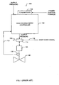
- FIG. 1 a block diagram of a known example electro-pneumatic control system 100 is shown.
- the electro-pneumatic control system 100 may be part of a process control or emergency shutdown system (not shown) that implements an industrial processing application, a commercial application, or any other desired application.
- the system 100 may be part of an industrial process control or emergency shutdown system that processes oil, gas, chemicals or the like.
- the system 100 includes an electro-pneumatic controller 102 that receives power and control signals via connections or terminations 104.
- the electro-pneumatic controller 102 receives one or more control signals such as, for example, a 4-20 mA signal, a 0-10 VDC signal, and/or digital commands, etc.
- the control signals may be used by the electro-pneumatic controller 102 as a set point to control its output pressure and/or the operation condition (e.g., the position) of a process control or emergency shutdown device 106 (which is depicted by way of example to be a valve).
- a process control or emergency shutdown device 106 which is depicted by way of example to be a valve.
- power and control signals may share one or more lines or wires coupled to the termination 104.
- the 4-20 mA control signal may also provide power to the electro-pneumatic controller 102.
- the control signal may, for example, be a 0-10 VDC signal and separate power wires or lines (e.g., 24 VDC or 24 volts alternating current (VAC)) may be provided to the electro-pneumatic controller 102.
- the power and/or control signals may share wires or line with digital data signals.
- a digital data communication protocol such as, for example, the well-known Highway Addressable Remote Transducer (HART) protocol may be used to communicate with the electro-pneumatic controller 102.
- HART Highway Addressable Remote Transducer
- Such digital communications may be used by the overall process control or emergency shutdown system to which the system 100 is coupled to retrieve identification information, operation status information and the like from the electro-pneumatic controller 102.
- the digital communications may be used to control or command the electro-pneumatic transducer 102 to perform one or more control functions.
- the terminations 104 may be screw terminals, insulation displacement connectors, pigtail connections, or any other type or combination of suitable electrical connections. Of course, the terminations 104 may be replaced or supplemented with one or more wireless communication links.
- the electro-pneumatic controller 102 may include one or more wireless transceiver units (not shown) to enable the electro-pneumatic controller 102 to exchange control information (set-point(s), operational status information, etc.) with the overall process control or emergency shutdown system. In the case where one or more wireless transceivers are used by the electro-pneumatic transducer 102, power may be supplied to the electro-pneumatic transducer via, for example, wires to a local or remote power supply.
- the output pressure of the electro-pneumatic controller 102 is provided to a pneumatic actuator 108 coupled to the process control operator or device 106.
- the process control operator or device 106 is depicted as being a valve, other devices or operators could be used instead (e.g., a damper).
- the pneumatic actuator 108 may be directly coupled to the device 106 or, alternatively, may be coupled to the device 106 via linkages or the like.
- an output shaft of the pneumatic actuator 108 may be directly coupled to a control shaft of the device 106.
- a position detector or sensor 110 may be used to provide a position feedback signal 112 to the electro-pneumatic controller 102. If provided, the position feedback signal 112 may be used by the electro-pneumatic controller 102 to vary its output pressure to precisely control the position of the process control or emergency shutdown device 106 (e.g., the percentage a valve is open/closed).
- the position sensor 110 may be implemented using any suitable sensor such as, for example, a hall-effect sensor, a linear voltage displacement transformer, a potentiometer, etc.
- a shut down or exhaust valve 114 interposes between the output pressure provided by the electro-pneumatic controller 102 and the actuator 108 and, in response to a shut down signal 116, vents the actuator 108 via an exhaust port 118 to atmosphere to cause the actuator 108 to stroke the process control device 106 to a known safe condition.
- the exhaust valve 110 may be implemented using a solenoid actuated three-way valve that receives a 24 VDC or 24 VAC shut down signal 112.
- the additional costs associated with field installing the exhaust valve 114 may be objectionable in many applications.
- electro-pneumatic controller 102 shown in FIG. 1 is depicted as having a single output pressure for use with a single-acting type actuator (e.g., the actuator 108), a pneumatic controller having two pressure outputs for use in a dual-acting application could be used as well.
- a dual acting electro-pneumatic controller is the DVC6000 series digital valve controller manufactured by Fisher Controls International, Inc. of Marshalltown, Iowa.
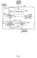
- FIG. 2 is a detailed block diagram of an example of an electro-pneumatic controller 200 having an integral shut down apparatus that may be used with the system 100 of FIG. 1 (e.g., in place of the electro-pneumatic controller 102).
- the example electro-pneumatic controller 200 includes a control unit 202, an electro-pneumatic transducer 204 and a pneumatic relay 206, all of which are generally well-known structures.
- the electro-pneumatic controller 200 includes a shut down unit 208 that interposes between the control unit 202 and the electro-pneumatic transducer 204 and further includes a shut down selector 210.
- control unit 202 receives one or more control signals (e.g., a 4-20 mA control signal) from the overall process control or emergency shutdown system to which it is communicatively coupled and provides a control signal 212 to the electro-pneumatic transducer 204 to achieve a desired output pressure and/or a desired control position of the process control device (e.g., the device 106 of FIG. 1 ) to which it is operatively coupled.
- the control unit 202 may be implemented using a processor-based system (e.g., the system 500 described below in connection with FIG. 5 ), discrete digital logic circuits, application specific integrated circuits, analog circuitry, or any combination thereof. In a case where a processor-based system is used to implement the control unit 202, the control unit 202 may execute machine readable instructions, firmware, software, etc. stored on a memory (not shown) within the control unit to perform its control functions.
- the electro-pneumatic transducer 204 may be a current-to-pressure type of transducer, in which case the control signal 212 is a current that is varied by the control unit 202 to achieve a desired condition (e.g., position) at the process control device 106 ( FIG. 1 ).
- the electro-pneumatic transducer 204 may be a voltage-to-pressure type of transducer, in which case the control signal 212 is a voltage that varies to control the process control device 106 ( FIG. 1 ).
- the pneumatic relay 206 converts a relatively low output capacity (i.e., low flow rate) pressure output 214 into a relatively high capacity output pressure for controlling an actuator (e.g., the actuator 108 of FIG. 1 ).
- the electro-pneumatic transducer 204 may receive an output pressure feedback signal 216 to provide a more accurate closed-loop control over the output pressure of the electro-pneumatic controller 200.
- the shut down unit 208 interposes between the control signal 212 and the electro-pneumatic transducer 204 and receives a signal 218 that is at least representative of the control signal input (e.g., the 4-20 mA control or set-point signal input) to the electro-pneumatic controller 200.
- the shut down selector 210 is operatively coupled to the shut down unit 208 to permit the selective enablement/disablement of the shut down unit 208.
- the control unit 202 receives a set-point or control signal(s) from the process control system to which it is communicatively coupled and outputs the control signal 212 to vary the output pressure 214 of the electro-pneumatic transducer 204 to achieve a desired condition (e.g., a percentage open/closed) at the process control device 106 ( FIG. 1 ).
- a desired condition e.g., a percentage open/closed
- the shut down unit 208 is completely transparent to the operation of the electro-pneumatic controller 200 and, thus, does not affect the operation of the electro-pneumatic controller 200, regardless of the magnitude of the control signal(s) input to the electro-pneumatic controller 200.
- the electro-pneumatic controller 200 may vary its output pressure based on the changes in the magnitude of the control signal(s) it receives when the control signal magnitude is above or below a predetermined threshold value. ln other words, the electro-pneumatic controller 200 may operate in the usual manner (i.e., vary its output pressure (e.g., in a proportional manner) in accordance with changes in the control signal(s) it receives.
- the shut down unit 208 may interrupt or otherwise prevent the control unit signal 212 from reaching the electro-pneumatic transducer 204.
- the shut down unit 208 may open a circuit path, short a circuit path, apply a predetermined shut down voltage or current, etc. to the electro-pneumatic transducer 204 to cause the electro-pneumatic transducer 204 to drive the pressure 214 and, thus, the output pressure of the controller 200 via the relay 206, to a shut down pressure (e.g., substantially zero pounds per square inch gauge).
- the shut down selector 210 is set to enable the shut down unit 208 and the electro-pneumatic controller 200 is used to control a process control device (e.g., the device 106 of FIG. 1 ) for use as an emergency shut down device.
- a process control device e.g., the device 106 of FIG. 1
- the electro-pneumatic controller 200 is configured to receive a 4-20 mA control signal, under non-emergency conditions a 20 mA signal may be continuously applied to the controller 200 to maintain the valve in a full open condition.
- the predetermined threshold used by the shut down unit 208 may be set at about 12 mA so that, upon detection of an emergency condition, the process control system (not shown) may reduce the control signal to well below 12 mA (e.g., to 4 mA), thereby causing the shut down unit 208 to prevent the signal 212 from reaching the electro-pneumatic transducer 204.
- the output pressure of the electro-pneumatic transducer 204 may be reduce to substantially near zero and, thus, the output pressure of the controller 200 may also be reduced to substantially near zero to close the valve 106.
- the electro-pneumatic transducer 200 is responsive to changes in the control signal so that the output pressure varies in proportion to the change in the control signal.
- live reliability tests such as, for example, partial stroke tests can be performed to determine that the controller 200 and the process control device to which it is coupled (e.g., the device 106 of FIG. 1 ) is operational.
- the control unit 202 may communicate the status (e.g., a successful shut down) of the process device coupled to the controller 200 to the overall process control system.
- the integral shut down unit 208 eliminates the costs associated with field mounting an additional safety device (e.g., a solenoid actuated venting valve) to vent the process control device coupled to the controller 200 in response to an emergency condition.
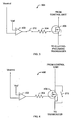
- FIGS. 3 and 4 are schematic representations of example circuits 300 and 400 that may be used to implement the shut down unit 208 and shut down selector 210 of FIG. 2 .
- the circuits 300 and 400 may include a comparator 302, the shut down selector 210, a resistor 304 and an electronic switch 306.
- the electronic switch 306 is depicted as being a metal oxide semiconductor field effect transistor (MOSFET).
- MOSFET metal oxide semiconductor field effect transistor
- any other suitable switching device such as, for example, a bipolar junction transistor (BJT), a field effect transistor (FET), an insulated gate bipolar junction transistor (IGBT), an electromechanical relay, or any other suitable switching mechanism could be used instead.
- shut down selector 210 is depicted as being a single pole single throw switch, other devices such as, for example, one or more removable wires, jumpers or circuit traces, a header and jumper combination, etc. could be used instead.
- a closed condition e.g., a closed circuit condition
- an open condition of the shut down selector 210 enables the circuit 400 for shut down operation.
- the non-inverting input of the comparator 302 is coupled to a reference voltage (Vref) and the inverting input is coupled to a voltage (Vcontrol) representative of the control signal provided to the controller 200 via the process control system.
- Vref is preferably selected so that it corresponds to a desired threshold value of the control signal (e.g., 12 mA as described above in connection with the example of FIG. 2 ).
- a desired threshold value of the control signal e.g., 12 mA as described above in connection with the example of FIG. 2 .
- control signal may be held at 20 mA, in which case Vcontrol will be held at its maximum value, which is greater than Vref.
- Vcontrol will be held at its maximum value, which is greater than Vref.
- the output of the comparator 302 is at a logical low condition (e.g., substantially near to or equal to its lower supply voltage, which may be a ground reference).
- a logical low output by the comparator 302 drives the switch 306 to a conducting condition in which the signal 212 from the control unit 202 is passed to the electro-pneumatic transducer 204.
- the process control system may reduce the control signal applied to the electro-pneumatic controller 200 to a low or its lowest possible value (e.g., 4 mA), which causes the voltage Vcontrol to fall below the reference voltage Vref.
- a low or its lowest possible value e.g. 4 mA
- the output of the comparator 302 transitions to a logical high output (e.g., its highest output voltage) to turn off the electronic switch 306, thereby preventing the signal 212 from being applied to the electro-pneumatic transducer 204.
- the shut down selector 210 may be used in series connection ( FIG. 3 ) with a switching control terminal (e.g., a gate) of the electronic switch 306, may be placed across two terminals ( FIG. 4 ), or in any other suitable configuration to provide the ability to enable/disable the operation of the shut down unit 208.
- a switching control terminal e.g., a gate
- FIG. 5 is an example processor system 500 that may be used to implement the control unit 202 of FIG. 2 .
- the processor system 500 includes a processor 512 that is coupled to an interconnection bus or network 514.
- the processor 512 may be any suitable processor, processing unit or microprocessor such as, for example, a processor from the Intel Itanium R family, Intel X-Scale R family, the Intel Pentium R family, etc.
- the system 500 may be a multi-processor system and, thus, may include one or more additional processors that are identical or similar to the processor 512 and which are coupled to the interconnection bus or network 514.
- the processor 512 of Fig. 5 is coupled to a chipset 518, which includes a memory controller 520 and an input/output (I/O) controller 522.
- a chipset typically provides I/O and memory management functions as well as a plurality of general purpose and/or special purpose registers, timers, etc. that are accessible or used by one or more processors coupled to the chipset.
- the memory controller 520 performs functions that enable the processor 512 (or processors if there are multiple processors) to access a system memory 524, which may include any desired type of volatile memory such as, for example, static random access memory (SRAM), dynamic random access memory (DRAM), etc.
- SRAM static random access memory
- DRAM dynamic random access memory
- the I/O controller 522 performs functions that enable the processor 512 to communicate with peripheral input/output (I/O) devices 526 and 528 via an I/O bus 530.
- the I/O devices 526 and 528 may be any desired type of I/O device such as, for example, a keyboard or keypad, a video display or monitor, etc. While the memory controller 520 and the I/O controller 522 are depicted in Fig. 5 as separate functional blocks within the chipset 128, the functions performed by these blocks may be integrated within a single semiconductor circuit or may be implemented using two or more separate integrated circuits.
- an electro-pneumatic controller includes an electro-pneumatic transducer and a shut down unit operatively coupled to the electro-pneumatic transducer.
- the shut down unit may be configured to respond to a signal received by the electro-pneumatic controller and to cause the electro-pneumatic transducer to provide a pressure output associated with a shut-down condition when the magnitude of the signal crosses a threshold value.
- a shut down unit for use with an electro-pneumatic controller includes an electronic switch configured to receive a first signal from a control unit of the electro-pneumatic controller and to convey the first signal to an electro-pneumatic transducer of the electro-pneumatic controller. Additionally, the electronic switch is further configured to receive a second signal associated with a control signal input and to cause the electronic switch to prevent the conveyance of the first signal to the electro-pneumatic transducer.
Claims (13)
- Abschaltungseinheit (208) zur Verwendung mit einem elektropneumatischen Regler (200), Folgendes umfassend:einen Schalter (306), der dazu ausgelegt ist, ein erstes Signal (212) von einer Steuereinheit (202) des elektropneumatischen Reglers zu empfangen und das erste Signal an einen elektropneumatischen Wandler (204) des elektropneumatischen Reglers zu übertragen, wobei der Schalter darüber hinaus dazu ausgelegt ist, ein zweites Signal (218, V-Regelung), das für einen Steuersignaleingang steht, zu empfangen, um zu bestimmen, ob der Schalter das erste Signal an den elektropneumatischen Wandler übertragen soll,dadurch gekennzeichnet, dassdas zweite Signal (218, V-Regelung) in die Steuereinheit (202) eingegeben wird, und dass die Bestimmung erfolgt, indem das zweite Signal mit einem vorbestimmten Schwellenwert verglichen wird, und um den Schalter zu veranlassen, die Übertragung des ersten Signals an den elektropneumatischen Wandler im Ansprechen auf den Vergleich des zweiten Signals mit dem Schwellenwert zu verhindern oder zuzulassen.
- Abschaltungseinheit nach Anspruch 1, wobei der Schalter entweder einen Transistor (306) oder ein Relais (210) umfasst.
- Abschaltungseinheit nach Anspruch 2, wobei der Transistor einen Gate-Anschluss umfasst, der auf das zweite Signal anspricht.
- Abschaltungseinheit nach Anspruch 1, darüber hinaus einen Komparator (302) umfassend, der dazu ausgelegt ist, das zweite Signal mit einer Bezugsspannung (Vref) zu vergleichen und die Übertragung des ersten Signals an den elektropneumatischen Wandler auf Grundlage des Vergleichs zu verhindern.
- Abschaltungseinheit nach Anspruch 1, wobei das zweite Signal für den Steuersignaleingang steht, der ein Sollwertsignal an den elektropneumatischen Regler angibt.
- Abschaltungseinheit nach Anspruch 1, wobei ein Abschaltungsselektor (210) dazu ausgelegt ist, selektiv den Betrieb der Abschaltungseinheit freizugeben.
- Abschaltungseinheit nach einem der Ansprüche 1, 4 und 5, wobei die Abschaltungseinheit in Wirkverbindung an einem Abschaltungsselektor (210) angeschlossen ist, um eine selektive Freigabe/Nichtfreigabe der Abschaltungseinheit zu gestatten.
- Abschaltungseinheit nach Anspruch 6 oder 7, wobei der Abschaltungsselektor einen manuellen Schalter umfasst.
- Elektropneumatischer Regler, Folgendes umfassend:einen elektropneumatischen Wandler; undeine Abschaltungseinheit nach Anspruch 1;wobei die Abschaltungseinheit dazu ausgelegt ist, auf das erste Signal anzusprechen, das durch den elektropneumatischen Regler empfangen wird, und den elektropneumatischen Wandler dazu zu veranlassen, einen mit einer Abschaltungsbedingung zusammenhängenden Ausgangsdruck bereitzustellen, wenn das Signal den Schwellenwert überschreitet.
- Elektropneumatischer Regler nach Anspruch 9, wobei die Abschaltungseinheit einen Komparator umfasst, der dazu ausgelegt ist, das durch den elektropneumatischen Regler empfangene Signal mit dem Schwellenwert zu vergleichen und auf Grundlage des Vergleichs eine Bedingung der Abschaltungseinheit zu verändern, um den elektropneumatischen Wandler dazu zu veranlassen, den mit der Abschaltungsbedingung zusammenhängenden Ausgangsdruck bereitzustellen.
- Elektropneumatischer Regler nach Anspruch 9, wobei der Schalter dazu ausgelegt ist, auf das zweite, dem elektropneumatischen Regler bereitgestellte Signal anzusprechen, um den elektropneumatischen Regler dazu zu veranlassen, den mit der Abschaltungsbedingung zusammenhängenden Ausgangsdruck bereitzustellen.
- Elektropneumatischer Regler nach Anspruch 11, wobei der Schalter entweder einen Transistor (306) oder ein Relais (210) umfasst.
- Elektropneumatischer Regler nach Anspruch 9, wobei der Abschaltungsselektor einen manuell betätigten Schalter umfasst.
Applications Claiming Priority (2)
| Application Number | Priority Date | Filing Date | Title |
|---|---|---|---|
| US10/721,848 US20050109395A1 (en) | 2003-11-25 | 2003-11-25 | Shut down apparatus and method for use with electro-pneumatic controllers |
| PCT/US2004/034758 WO2005057301A1 (en) | 2003-11-25 | 2004-10-20 | Shut down apparatus and method for use with electro-pneumatic controllers |
Publications (2)
| Publication Number | Publication Date |
|---|---|
| EP1695155A1 EP1695155A1 (de) | 2006-08-30 |
| EP1695155B1 true EP1695155B1 (de) | 2013-08-21 |
Family
ID=34591900
Family Applications (1)
| Application Number | Title | Priority Date | Filing Date |
|---|---|---|---|
| EP20040795862 Revoked EP1695155B1 (de) | 2003-11-25 | 2004-10-20 | Herunterfahrvorrichtung und verfahren zur verwendung mit elektropneumatischen steuerungen |
Country Status (9)
| Country | Link |
|---|---|
| US (1) | US20050109395A1 (de) |
| EP (1) | EP1695155B1 (de) |
| JP (1) | JP4851339B2 (de) |
| CN (1) | CN100504671C (de) |
| AR (1) | AR047129A1 (de) |
| BR (1) | BRPI0415877B1 (de) |
| CA (1) | CA2543394C (de) |
| MX (1) | MXPA06005713A (de) |
| WO (1) | WO2005057301A1 (de) |
Cited By (1)
| Publication number | Priority date | Publication date | Assignee | Title |
|---|---|---|---|---|
| EP1984630B1 (de) | 2006-02-07 | 2015-10-07 | Dresser, Inc. | Sicherheitsvorrangschaltung für pneumatisches stellglied und verwendungsverfahren dafür |
Families Citing this family (30)
| Publication number | Priority date | Publication date | Assignee | Title |
|---|---|---|---|---|
| US8145180B2 (en) | 2004-05-21 | 2012-03-27 | Rosemount Inc. | Power generation for process devices |
| US8160535B2 (en) * | 2004-06-28 | 2012-04-17 | Rosemount Inc. | RF adapter for field device |
| US8787848B2 (en) | 2004-06-28 | 2014-07-22 | Rosemount Inc. | RF adapter for field device with low voltage intrinsic safety clamping |
| US7262693B2 (en) * | 2004-06-28 | 2007-08-28 | Rosemount Inc. | Process field device with radio frequency communication |
| US7852610B2 (en) * | 2006-01-24 | 2010-12-14 | Fisher Controls International Llc | Flameproof apparatus using non-grounded energy-limiting barrier |
| JP4671131B2 (ja) * | 2006-08-10 | 2011-04-13 | 横河電機株式会社 | 安全計装システム |
| DE102006038503B4 (de) * | 2006-08-16 | 2014-01-23 | Phoenix Contact Gmbh & Co. Kg | Verfahren zum Kennzeichnen des Betriebszustandes eines Bedienelementes und Steuerungsvorrichtung |
| US8573241B2 (en) * | 2007-03-30 | 2013-11-05 | Dresser, Inc. | Systems and processes for field-initiated fluid regulation testing |
| US7818093B2 (en) | 2007-04-27 | 2010-10-19 | Dresser, Inc. | Controlling fluid regulation |
| DE102007050708B4 (de) * | 2007-10-22 | 2009-08-06 | Phoenix Contact Gmbh & Co. Kg | System zum Betreiben wenigstens eines nicht-sicherheitskritischen und wenigstens eines sicherheitskritischen Prozesses |
| US8929948B2 (en) | 2008-06-17 | 2015-01-06 | Rosemount Inc. | Wireless communication adapter for field devices |
| WO2009154749A1 (en) * | 2008-06-17 | 2009-12-23 | Rosemount Inc. | Rf adapter for field device with loop current bypass |
| US8694060B2 (en) | 2008-06-17 | 2014-04-08 | Rosemount Inc. | Form factor and electromagnetic interference protection for process device wireless adapters |
| WO2009154756A1 (en) | 2008-06-17 | 2009-12-23 | Rosemount Inc. | Rf adapter for field device with variable voltage drop |
| US9674976B2 (en) | 2009-06-16 | 2017-06-06 | Rosemount Inc. | Wireless process communication adapter with improved encapsulation |
| US8626087B2 (en) | 2009-06-16 | 2014-01-07 | Rosemount Inc. | Wire harness for field devices used in a hazardous locations |
| US8996328B2 (en) * | 2009-12-29 | 2015-03-31 | Fisher Controls International Llc | Methods, apparatus and articles of manufacture to test safety instrumented system solenoids |
| US10761524B2 (en) | 2010-08-12 | 2020-09-01 | Rosemount Inc. | Wireless adapter with process diagnostics |
| US9459619B2 (en) * | 2011-06-29 | 2016-10-04 | Mega Fluid Systems, Inc. | Continuous equipment operation in an automated control environment |
| JP5843558B2 (ja) * | 2011-10-14 | 2016-01-13 | アズビル株式会社 | ポジショナ |
| US9310794B2 (en) | 2011-10-27 | 2016-04-12 | Rosemount Inc. | Power supply for industrial process field device |
| DE102013105994A1 (de) * | 2013-06-10 | 2014-12-11 | Endress + Hauser Conducta Gesellschaft für Mess- und Regeltechnik mbH + Co. KG | Messsystem mit zumindest einem Feldgerät mit zumindest einer Anzeigevorrichtung sowie Verfahren zum Betreiben desselben |
| US10185291B2 (en) * | 2013-06-28 | 2019-01-22 | Fisher Controls International Llc | System and method for shutting down a field device |
| DE102013218731A1 (de) * | 2013-09-18 | 2015-03-19 | Stotz Feinmesstechnik Gmbh | Vorrichtung zur pneumatischen Objektvermessung |
| US9989159B2 (en) | 2014-05-01 | 2018-06-05 | Fisher Controls International Llc | Vent assembly and method for a digital valve positioner |
| JP2017194122A (ja) * | 2016-04-21 | 2017-10-26 | アズビル株式会社 | ポジショナおよびバルブ制御システム |
| US10670054B2 (en) * | 2017-10-25 | 2020-06-02 | Dresser, Llc | Constructing valve positioners for hazardous areas |
| US11306748B2 (en) * | 2017-10-25 | 2022-04-19 | Dresser, Llc | Constructing valve positioners for hazardous areas |
| US10746314B2 (en) * | 2018-09-14 | 2020-08-18 | Fisher Controls International Llc | Positioner apparatus for use with fluid valves |
| US11774127B2 (en) | 2021-06-15 | 2023-10-03 | Honeywell International Inc. | Building system controller with multiple equipment failsafe modes |
Family Cites Families (19)
| Publication number | Priority date | Publication date | Assignee | Title |
|---|---|---|---|---|
| FR2619262B1 (fr) * | 1987-08-06 | 1994-09-23 | Crouzet Sa | Dispositif de protection d'un equipement contre les surtensions induites sur une ligne lui etant raccordee |
| JPH01236311A (ja) * | 1988-03-16 | 1989-09-21 | Nec Corp | 状態監視回路 |
| JPH04205202A (ja) * | 1990-11-30 | 1992-07-27 | Yamatake Honeywell Co Ltd | フィールド装置 |
| JPH04335796A (ja) * | 1991-05-13 | 1992-11-24 | Toshiba Corp | ハンドヘルドターミナル |
| JPH04343021A (ja) * | 1991-05-20 | 1992-11-30 | Yamatake Honeywell Co Ltd | 電磁流量計 |
| JP2697399B2 (ja) * | 1991-09-13 | 1998-01-14 | 三菱電機株式会社 | 位置決め装置及びそのプログラム表示方法 |
| JP2607408B2 (ja) * | 1991-10-21 | 1997-05-07 | 山武ハネウエル株式会社 | ポジショナ |
| JPH06119589A (ja) * | 1992-03-31 | 1994-04-28 | Y K V Kk | 弁開度計 |
| IT1264866B1 (it) * | 1993-06-22 | 1996-10-17 | Nuovo Pignone Spa | Convertitore elettropneumatico perfezionato con comando ad elettrovalvole |
| DE4429401C2 (de) * | 1994-08-09 | 1999-01-07 | Hartmann & Braun Gmbh & Co Kg | Druckmittelbetriebener Stellantrieb |
| JPH10166193A (ja) * | 1996-12-06 | 1998-06-23 | Komatsu Ltd | 光線式安全装置の無効解除装置及びその方法 |
| DE69701628T2 (de) * | 1997-07-18 | 2001-02-01 | Ansaldo Sistemi Spa | Elektronischer Schaltkreis zur Transientenminderung beim Einschalten |
| JP3543132B2 (ja) * | 1997-07-29 | 2004-07-14 | ノーリツ鋼機株式会社 | 写真感光材料の自動現像処理装置 |
| FI116587B (fi) * | 1997-10-17 | 2005-12-30 | Metso Automation Oy | Menetelmä ja laitteisto turvalaitteen toimintakunnon todentamiseksi |
| JP2000265907A (ja) * | 1999-03-18 | 2000-09-26 | Nichias Corp | 内燃機関の部品用ヒーターの通電制御回路基板 |
| JP2000210891A (ja) * | 1999-01-19 | 2000-08-02 | Yaskawa Electric Corp | ロボット駆動装置の安全保護装置 |
| US6318234B1 (en) * | 2000-06-30 | 2001-11-20 | Caterpillar Inc. | Line vent arrangement for electro-hydraulic circuit |
| US6862547B2 (en) * | 2001-04-05 | 2005-03-01 | Saudi Arabian Oil Company | Control device test system with a remote switch activation |
| JP2003097315A (ja) * | 2001-09-20 | 2003-04-03 | Honda Motor Co Ltd | 汎用エンジンの制御装置 |
-
2003
- 2003-11-25 US US10/721,848 patent/US20050109395A1/en not_active Abandoned
-
2004
- 2004-10-20 EP EP20040795862 patent/EP1695155B1/de not_active Revoked
- 2004-10-20 CA CA2543394A patent/CA2543394C/en active Active
- 2004-10-20 BR BRPI0415877-6A patent/BRPI0415877B1/pt active IP Right Grant
- 2004-10-20 MX MXPA06005713A patent/MXPA06005713A/es active IP Right Grant
- 2004-10-20 JP JP2006541172A patent/JP4851339B2/ja active Active
- 2004-10-20 WO PCT/US2004/034758 patent/WO2005057301A1/en active Application Filing
- 2004-10-20 CN CNB2004800314982A patent/CN100504671C/zh active Active
- 2004-11-19 AR ARP040104293 patent/AR047129A1/es active IP Right Grant
Cited By (1)
| Publication number | Priority date | Publication date | Assignee | Title |
|---|---|---|---|---|
| EP1984630B1 (de) | 2006-02-07 | 2015-10-07 | Dresser, Inc. | Sicherheitsvorrangschaltung für pneumatisches stellglied und verwendungsverfahren dafür |
Also Published As
| Publication number | Publication date |
|---|---|
| CA2543394C (en) | 2015-08-04 |
| AR047129A1 (es) | 2006-01-11 |
| BRPI0415877B1 (pt) | 2020-12-01 |
| JP2007512622A (ja) | 2007-05-17 |
| CN100504671C (zh) | 2009-06-24 |
| CA2543394A1 (en) | 2005-06-23 |
| CN1871558A (zh) | 2006-11-29 |
| WO2005057301A1 (en) | 2005-06-23 |
| MXPA06005713A (es) | 2006-08-17 |
| EP1695155A1 (de) | 2006-08-30 |
| BRPI0415877A (pt) | 2007-01-09 |
| JP4851339B2 (ja) | 2012-01-11 |
| US20050109395A1 (en) | 2005-05-26 |
Similar Documents
| Publication | Publication Date | Title |
|---|---|---|
| EP1695155B1 (de) | Herunterfahrvorrichtung und verfahren zur verwendung mit elektropneumatischen steuerungen | |
| CN101379301B (zh) | 用于气动定位器的安全超控电路及其使用方法 | |
| US8180466B2 (en) | Process device with supervisory overlayer | |
| US7539560B2 (en) | Control valve and positioner diagnostics | |
| EP1769159B1 (de) | Rückkopplungssteuerverfahren und vorrichtung für elektropneumatische steuersysteme | |
| EP2805142B1 (de) | Feldgerät mit selbstprüfungung eines piezoelektrischen wandlers | |
| EP2118544B1 (de) | Flüssigkeitsregelungssystem und verfahren | |
| WO2015105927A1 (en) | Valve positioner with overpressure protection capabilities | |
| US20060016201A1 (en) | Actuator alarm for critical environments or applications | |
| JP6444867B2 (ja) | 制御信号保護装置 | |
| US11359744B2 (en) | Method for monitoring a mechanical system | |
| CN105843268B (zh) | 具有过压保护能力的阀定位器 | |
| KR20090062383A (ko) | 선박 내에 설치된 복수의 컨트롤 밸브를 제어하기 위한제어장치 및 제어방법 |
Legal Events
| Date | Code | Title | Description |
|---|---|---|---|
| PUAI | Public reference made under article 153(3) epc to a published international application that has entered the european phase |
Free format text: ORIGINAL CODE: 0009012 |
|
| 17P | Request for examination filed |
Effective date: 20060622 |
|
| AK | Designated contracting states |
Kind code of ref document: A1 Designated state(s): DE FI FR GB SE |
|
| RBV | Designated contracting states (corrected) |
Designated state(s): DE FI FR GB SE |
|
| DAX | Request for extension of the european patent (deleted) | ||
| RBV | Designated contracting states (corrected) |
Designated state(s): DE FI FR GB SE |
|
| 17Q | First examination report despatched |
Effective date: 20071102 |
|
| GRAP | Despatch of communication of intention to grant a patent |
Free format text: ORIGINAL CODE: EPIDOSNIGR1 |
|
| GRAS | Grant fee paid |
Free format text: ORIGINAL CODE: EPIDOSNIGR3 |
|
| GRAP | Despatch of communication of intention to grant a patent |
Free format text: ORIGINAL CODE: EPIDOSNIGR1 |
|
| INTG | Intention to grant announced |
Effective date: 20130522 |
|
| GRAA | (expected) grant |
Free format text: ORIGINAL CODE: 0009210 |
|
| AK | Designated contracting states |
Kind code of ref document: B1 Designated state(s): DE FI FR GB SE |
|
| REG | Reference to a national code |
Ref country code: GB Ref legal event code: FG4D |
|
| REG | Reference to a national code |
Ref country code: DE Ref legal event code: R096 Ref document number: 602004043127 Country of ref document: DE Effective date: 20131017 |
|
| REG | Reference to a national code |
Ref country code: SE Ref legal event code: TRGR |
|
| PLBI | Opposition filed |
Free format text: ORIGINAL CODE: 0009260 |
|
| PLAX | Notice of opposition and request to file observation + time limit sent |
Free format text: ORIGINAL CODE: EPIDOSNOBS2 |
|
| 26 | Opposition filed |
Opponent name: SAMSON AG Effective date: 20140521 |
|
| REG | Reference to a national code |
Ref country code: DE Ref legal event code: R026 Ref document number: 602004043127 Country of ref document: DE Effective date: 20140521 |
|
| PLBB | Reply of patent proprietor to notice(s) of opposition received |
Free format text: ORIGINAL CODE: EPIDOSNOBS3 |
|
| REG | Reference to a national code |
Ref country code: FR Ref legal event code: PLFP Year of fee payment: 12 |
|
| PGFP | Annual fee paid to national office [announced via postgrant information from national office to epo] |
Ref country code: GB Payment date: 20151027 Year of fee payment: 12 Ref country code: DE Payment date: 20151028 Year of fee payment: 12 |
|
| PGFP | Annual fee paid to national office [announced via postgrant information from national office to epo] |
Ref country code: SE Payment date: 20151028 Year of fee payment: 12 Ref country code: FR Payment date: 20151019 Year of fee payment: 12 |
|
| REG | Reference to a national code |
Ref country code: DE Ref legal event code: R064 Ref document number: 602004043127 Country of ref document: DE Ref country code: DE Ref legal event code: R103 Ref document number: 602004043127 Country of ref document: DE |
|
| RDAF | Communication despatched that patent is revoked |
Free format text: ORIGINAL CODE: EPIDOSNREV1 |
|
| RDAG | Patent revoked |
Free format text: ORIGINAL CODE: 0009271 |
|
| STAA | Information on the status of an ep patent application or granted ep patent |
Free format text: STATUS: PATENT REVOKED |
|
| 27W | Patent revoked |
Effective date: 20160511 |
|
| GBPR | Gb: patent revoked under art. 102 of the ep convention designating the uk as contracting state |
Effective date: 20160511 |
|
| PGFP | Annual fee paid to national office [announced via postgrant information from national office to epo] |
Ref country code: FI Payment date: 20161027 Year of fee payment: 13 |
|
| REG | Reference to a national code |
Ref country code: SE Ref legal event code: ECNC |