EP1694997B1 - Vorrichtung zum verbinden mit einem ende eines wellrohres - Google Patents
Vorrichtung zum verbinden mit einem ende eines wellrohres Download PDFInfo
- Publication number
- EP1694997B1 EP1694997B1 EP04803262A EP04803262A EP1694997B1 EP 1694997 B1 EP1694997 B1 EP 1694997B1 EP 04803262 A EP04803262 A EP 04803262A EP 04803262 A EP04803262 A EP 04803262A EP 1694997 B1 EP1694997 B1 EP 1694997B1
- Authority
- EP
- European Patent Office
- Prior art keywords
- section
- inserting section
- corrugated pipe
- depression
- arresting
- Prior art date
- Legal status (The legal status is an assumption and is not a legal conclusion. Google has not performed a legal analysis and makes no representation as to the accuracy of the status listed.)
- Expired - Lifetime
Links
- 238000007789 sealing Methods 0.000 claims description 8
- 210000001331 nose Anatomy 0.000 claims 2
- 238000000926 separation method Methods 0.000 claims 1
- 238000003780 insertion Methods 0.000 abstract description 32
- 230000037431 insertion Effects 0.000 abstract description 32
- 239000012530 fluid Substances 0.000 description 5
- 239000011324 bead Substances 0.000 description 2
- 230000008878 coupling Effects 0.000 description 2
- 238000010168 coupling process Methods 0.000 description 2
- 238000005859 coupling reaction Methods 0.000 description 2
- 230000000630 rising effect Effects 0.000 description 2
- 238000005452 bending Methods 0.000 description 1
- 230000006835 compression Effects 0.000 description 1
- 238000007906 compression Methods 0.000 description 1
- 230000001419 dependent effect Effects 0.000 description 1
- 238000011161 development Methods 0.000 description 1
- 230000018109 developmental process Effects 0.000 description 1
- 239000000463 material Substances 0.000 description 1
- 230000000284 resting effect Effects 0.000 description 1
Images


Classifications
-
- F—MECHANICAL ENGINEERING; LIGHTING; HEATING; WEAPONS; BLASTING
- F16—ENGINEERING ELEMENTS AND UNITS; GENERAL MEASURES FOR PRODUCING AND MAINTAINING EFFECTIVE FUNCTIONING OF MACHINES OR INSTALLATIONS; THERMAL INSULATION IN GENERAL
- F16L—PIPES; JOINTS OR FITTINGS FOR PIPES; SUPPORTS FOR PIPES, CABLES OR PROTECTIVE TUBING; MEANS FOR THERMAL INSULATION IN GENERAL
- F16L25/00—Construction or details of pipe joints not provided for in, or of interest apart from, groups F16L13/00 - F16L23/00
- F16L25/0036—Joints for corrugated pipes
- F16L25/0045—Joints for corrugated pipes of the quick-acting type
Definitions
- the invention relates to a device for connecting to one end of a corrugated pipe, according to the preamble of the expression 1.
- a device for connecting to one end of a corrugated pipe, according to the preamble of the expression 1.
- Such a device is known from DE-A-101 58 114 known.
- a device for connecting to one end of a corrugated tube is further from the US-A-5,335,945 known.
- This device has a receiving section made of a flexible, stretchable plastic material into which one end of a corrugated tube can be inserted until it comes into contact with a stop flange while radially expanding the receiving section.
- the invention has for its object to provide a device for connecting to one end of a corrugated pipe, which is characterized by the highest density by easy handling.
- one end of a corrugated tube can be pushed tightly onto the insertion section with slight expansion and can be reliably connected to the device by the clamping arrangement formed with at least one engagement nose.
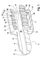
- Fig. 1 shows a partially cutaway perspective view of a first embodiment of a device.
- the exemplary embodiment according to FIG. 1 has an elongate connecting portion 1, which at an insertion end 2 has a plug-in cone tapering in the direction of the insertion end 2 3 'is formed.
- the connecting portion 1 is used to connect the device, for example, with a smooth-walled hose of a fluid line system, not shown in Fig. 1.
- an annular collar 5 is formed, which projects in radial directions beyond the maximum diameter of the sealing beads 4 and thus forms a stop from the side of the insertion end 2.
- a resilient first clip bracket 6 and a resilient second clip bracket 7 of a Kiammeran extract are attached diametrically opposite each other in the embodiment of FIG. 1, which extend in the direction of the insertion end 2 opposite Einglageendes 8.
- an elongated insertion section 9 is made from the annular collar 5 in the direction of the insertion end 8 as an extension of the insertion end 2.
- the clip brackets 6, 7 are arranged substantially parallel and at a distance from the insertion portion 9.
- the connecting portion 1 and the inserting portion 9 surround a fluid channel 10 extending from the insertion end 2 to the insertion end 8.
- a first cone section 11 and between the first cone section 11 and the annular collar 5, a second cone section 12 are formed in the embodiment of FIG. 1 adjacent to the insertion end 8.
- the cone sections 11, 12 each have one in an insertion direction in from the insert 8.
- the retaining surfaces 14 are significantly steeper with respect to the longitudinal axis relative to the sliding surfaces 13, for example, as in the embodiment of FIG. 1 at right angles, employed to the longitudinal axis of the device.
- the clamp brackets 6, 7 have at their lying in the region of the insertion end 8 free ends in each case a radially inwardly facing Eingreifnase 15, mit.einer the .Einhegeende 8, from the insertion end 8 in the direction of the annular collar 5 radially inwardly tapered sliding surface 16 and one of the insertion end 8 facing away, substantially perpendicular to the longitudinal axis of the device aligned stop surface 17 are formed.
- FIG. 1 one end of a corrugated tube 18 is shown, whose wall is formed in the longitudinal direction with a sequence of radially oriented elevations and depressions.
- the end of the corrugated tube 18 is slid over the insertion section 9 as far as the abutment against the annular collar 5, wherein the radial areas of the corrugated tube 18 closest to the longitudinal axis of the corrugated tube 18 bear against the sliding surfaces 13 of the cone sections 11, 12 and are slightly wider than the original inner diameter. Due to the radially inwardly acting force achieved thereby, sealing of the corrugated tube 18 against the insertion section 9 is achieved.
- the engagement lugs 15 engage behind the abutment surfaces 17 at radially inwardly sloping wall portions of the corrugated tube 18 a radially outwardly projecting increase in the wall of the corrugated pipe 18 after 18 in the insertion of the corrugated tube under bending the resilient clip bracket 6, 7 radially outward over a number Raised from radially outwardly protruding elevations of the wall of the corrugated tube 18.
- the corrugated tube 18 is secured against unintentional withdrawal from the device.
- Fig. 2 shows in a partially sectioned perspective view of an embodiment of the invention, wherein in the embodiments according to FIGS. 1 and Fig. 2 corresponding elements provided with the same reference numerals and are not explained in further detail in matches.
- the connecting portion 1 of the embodiment of FIG. 2 is channel-like and has a number of inside and outside elevations and depressions, which are adapted for receiving and locking a coupling piece, not shown in FIG. 2 for connection to a fluid conduit system.
- the insertion section 9 of the exemplary embodiment according to FIG. 2 has a single cone section 19 with a sliding surface 13 inclined in accordance with the exemplary embodiment according to FIG. 1.
- the sliding surface 13 points away from the insertion end 8 a rubber-like sealing body 20 enclosing the insertion section 9 in an annular manner.
- the clamp arrangement has an annular closed sliding sleeve 21, which in the axial direction under compression of the clamp brackets 6, 7 in the radial direction from a release recess 22 exposed in the representation according to FIG in the direction of the inserting end 8, a slippery surface 23 rising in a direction in the region of the engagement lugs 15 is inserted into the clamp bracket 6, 7 and can be displaced.
- the locking recess 24 has substantially radially aligned boundary sides, so that the sliding sleeve 21 after engagement in the locking recess 24 only after targeted and relatively complex manipulation of the locking recess 24, is removable.
- Fig. 3 shows in a partially sectioned perspective view of a third embodiment, wherein in the embodiments of FIG. 1, Fig. 2 and Fig. 3 corresponding elements are provided with the same reference numerals and are not further explained in the following.
- the exemplary embodiment according to FIG. 3 has a connecting section 1 which is channel-like and has a number of inside and outside elevations and depressions, which are used to receive and lock a coupling piece not shown in FIG are set up with a fluid line system.
- the insertion section 9 is formed over its entire length with a conical sliding surface 13 of a single cone section 19, which rises in a direction away from the insertion end 8 and ends at a radially oriented end surface 25.
- a rubber-like sealing body 20 is pushed, on which a number of radially to projecting elevations of the wall of a corrugated tube 18 come to rest.
- the clamp arrangement for fixing the corrugated tube 18 in the embodiment according to FIG. 3 comprises a C-shaped snap ring 26 which can be inserted along a radially aligned insertion direction into a ring receptacle 28 provided at the edge of the insertion end 8 and closed at the edge by a terminating flange 27.
- the snap ring 26 has radially on the inside a circumferential engagement lug 15, which engages behind a radially outwardly projecting elevation of the wall of the corrugated pipe 18 at a proper arrangement of the snap ring 26 over a relatively large circumference.
Landscapes
- Engineering & Computer Science (AREA)
- General Engineering & Computer Science (AREA)
- Mechanical Engineering (AREA)
- Quick-Acting Or Multi-Walled Pipe Joints (AREA)
- Joints That Cut Off Fluids, And Hose Joints (AREA)
- Feeding And Controlling Fuel (AREA)
- Joints With Sleeves (AREA)
Applications Claiming Priority (2)
| Application Number | Priority Date | Filing Date | Title |
|---|---|---|---|
| DE10357892A DE10357892A1 (de) | 2003-12-11 | 2003-12-11 | Vorrichtung zum Verbinden mit einem Ende eines Wellrohres |
| PCT/EP2004/013353 WO2005057072A1 (de) | 2003-12-11 | 2004-11-25 | Vorrichtung zum verbinden mit einem ende eines wellrohres |
Publications (2)
| Publication Number | Publication Date |
|---|---|
| EP1694997A1 EP1694997A1 (de) | 2006-08-30 |
| EP1694997B1 true EP1694997B1 (de) | 2008-01-23 |
Family
ID=34672579
Family Applications (1)
| Application Number | Title | Priority Date | Filing Date |
|---|---|---|---|
| EP04803262A Expired - Lifetime EP1694997B1 (de) | 2003-12-11 | 2004-11-25 | Vorrichtung zum verbinden mit einem ende eines wellrohres |
Country Status (8)
| Country | Link |
|---|---|
| US (1) | US20070126230A1 (https=) |
| EP (1) | EP1694997B1 (https=) |
| JP (1) | JP2007514108A (https=) |
| CN (1) | CN100420893C (https=) |
| AT (1) | ATE384904T1 (https=) |
| DE (2) | DE10357892A1 (https=) |
| ES (1) | ES2298846T3 (https=) |
| WO (1) | WO2005057072A1 (https=) |
Families Citing this family (14)
| Publication number | Priority date | Publication date | Assignee | Title |
|---|---|---|---|---|
| SE530948C2 (sv) * | 2005-10-19 | 2008-10-28 | Kongsberg Automotive As | Skyddsorgan för hankontaktelement |
| DE102005060136B3 (de) * | 2005-12-16 | 2007-01-04 | A. Raymond Et Cie | Kupplung |
| DE202006001126U1 (de) * | 2006-01-24 | 2006-04-27 | Technaflon Ag | Rohrverbindung mit Sicherungsmittel |
| CN201269379Y (zh) * | 2008-11-03 | 2009-07-08 | 天津市润实科技发展有限公司 | 一种具有定位作用的管接头 |
| US8091928B2 (en) * | 2009-02-26 | 2012-01-10 | Eaton Corporation | Coupling assembly for connection to a hose |
| DE102011005220A1 (de) | 2011-03-08 | 2012-09-13 | Fränkische Industrial Pipes GmbH & Co. KG | Verbindungsanordnung |
| DE102012109785B4 (de) | 2012-10-15 | 2018-04-05 | Contitech Mgw Gmbh | Verbindungselement zur Verbindung eines unelastischen Rohres mit einem elastischen Schlauch |
| CN103398254B (zh) * | 2013-08-15 | 2018-07-27 | 昆山联华印务有限公司 | 波纹软管的管接头 |
| WO2015092830A1 (ja) * | 2013-12-18 | 2015-06-25 | ボルボトラックコーポレーション | コルゲートチューブの保持部材 |
| US11085566B2 (en) * | 2017-12-22 | 2021-08-10 | The Boeing Company | Pressure sleeve |
| GB2582132B (en) * | 2019-03-10 | 2023-05-03 | Mcalpine & Co Ltd | Plumbing connector, assembly and method |
| EP3995728A1 (de) * | 2020-11-10 | 2022-05-11 | Viessmann Climate Solutions SE | Verbindungsvorrichtung für ein umfangsgeripptes rohr |
| DE102021112893A1 (de) | 2021-05-18 | 2022-11-24 | CENA-Kunststoff GmbH | Verbinder für ein Wellrohr |
| IT202200027096A1 (it) * | 2022-12-29 | 2024-06-29 | Euro 2000 S P A | Raccordo, particolarmente per tubi corrugati e simili. |
Family Cites Families (19)
| Publication number | Priority date | Publication date | Assignee | Title |
|---|---|---|---|---|
| US3724882A (en) * | 1971-05-10 | 1973-04-03 | Ford Motor Co | Tube-to-hose connection |
| JPH0510498Y2 (https=) * | 1987-04-28 | 1993-03-15 | ||
| DE3808383A1 (de) * | 1988-03-12 | 1989-09-28 | Witzenmann Metallschlauchfab | Leitungsverbindung |
| DE3903355A1 (de) * | 1989-02-04 | 1990-08-09 | Hummel Metallwarenfab A | Anschlussarmatur fuer umfangsgerippte schlaeuche oder rohre |
| DE4018768A1 (de) * | 1989-06-15 | 1990-12-20 | Em Technik Gmbh Armaturenbau | Druckfeste verschraubung fuer gewellte schlaeuche insbesondere aus kunststoff |
| US5113900A (en) * | 1991-01-30 | 1992-05-19 | Bridge Products, Inc. | Check valve with quick lock attachment feature |
| US5335945A (en) * | 1992-07-14 | 1994-08-09 | Tuf-Tite, Inc. | Flexible pipe connector |
| WO1994023775A1 (en) * | 1993-03-23 | 1994-10-27 | Abbott Laboratories | Securing collar for cannula connector |
| US5794986A (en) * | 1994-09-15 | 1998-08-18 | Infrasonics, Inc. | Semi-disposable ventilator breathing circuit tubing with releasable coupling |
| US6254145B1 (en) * | 1997-03-07 | 2001-07-03 | Pma Ag | Joining and connecting element for corrugated pipes |
| DE19723410A1 (de) * | 1997-06-04 | 1998-12-10 | Bosch Gmbh Robert | Anordnung zum Befestigen eines Wellrohrs auf einem Stutzen |
| US5984375A (en) * | 1997-07-23 | 1999-11-16 | Schlumberger Industries, Inc. | Hose collar and method of use therefor |
| US6173995B1 (en) * | 1998-02-04 | 2001-01-16 | Titeflex Corporation | Self-flaring, split bushing pipe fitting and hose assemblies employing same |
| FR2776747B1 (fr) * | 1998-03-27 | 2000-06-02 | Hutchinson | Raccord encliquetable pour tuyau de transfert de fluide |
| DE19943764C5 (de) * | 1999-09-13 | 2004-07-29 | Schlemmer Gmbh | Anschlußvorrichtung für eine Wellschlauchleitung und Leitungssystem |
| EP1103752A1 (en) * | 1999-11-26 | 2001-05-30 | Eureka Immobiliare S.r.l. | Flexible corrugated tube with end fittings for hydraulic systems |
| DE10104449C2 (de) * | 2001-02-01 | 2003-11-13 | Eaton Fluid Power Gmbh | Wellrohrschlaucharmatur |
| DE10158114B4 (de) * | 2001-11-27 | 2011-03-17 | Fränkische Rohrwerke Gebr. Kirchner GmbH + Co. KG | Anschlussvorrichtung für Wellschauchleitung und Leitungssystem |
| DE20219220U1 (de) * | 2002-12-12 | 2003-02-27 | Buderus Heiztechnik Gmbh, 35576 Wetzlar | Anordnung zum Verbinden von Leitungsabschnitten |
-
2003
- 2003-12-11 DE DE10357892A patent/DE10357892A1/de not_active Withdrawn
-
2004
- 2004-11-25 ES ES04803262T patent/ES2298846T3/es not_active Expired - Lifetime
- 2004-11-25 JP JP2006543417A patent/JP2007514108A/ja not_active Withdrawn
- 2004-11-25 AT AT04803262T patent/ATE384904T1/de not_active IP Right Cessation
- 2004-11-25 CN CNB2004800369684A patent/CN100420893C/zh not_active Expired - Fee Related
- 2004-11-25 DE DE502004006084T patent/DE502004006084D1/de not_active Expired - Fee Related
- 2004-11-25 EP EP04803262A patent/EP1694997B1/de not_active Expired - Lifetime
- 2004-11-25 WO PCT/EP2004/013353 patent/WO2005057072A1/de not_active Ceased
- 2004-11-25 US US10/596,271 patent/US20070126230A1/en not_active Abandoned
Also Published As
| Publication number | Publication date |
|---|---|
| CN1894530A (zh) | 2007-01-10 |
| ATE384904T1 (de) | 2008-02-15 |
| WO2005057072A1 (de) | 2005-06-23 |
| DE502004006084D1 (de) | 2008-03-13 |
| EP1694997A1 (de) | 2006-08-30 |
| CN100420893C (zh) | 2008-09-24 |
| DE10357892A1 (de) | 2005-07-14 |
| JP2007514108A (ja) | 2007-05-31 |
| ES2298846T3 (es) | 2008-05-16 |
| US20070126230A1 (en) | 2007-06-07 |
Similar Documents
| Publication | Publication Date | Title |
|---|---|---|
| EP1694997B1 (de) | Vorrichtung zum verbinden mit einem ende eines wellrohres | |
| DE19741641C2 (de) | Anschlußvorrichtung für ein Rohr- oder Schlauchteil | |
| EP1395771B1 (de) | Lösbare steckkupplung mit schutzhülse | |
| DE69209919T2 (de) | Anzeigevorrichtung für eine Schnellverschlusskupplung | |
| EP1781979B1 (de) | Steckverbindung für fluid-leitungen | |
| DE19809313C1 (de) | Verbindungseinheit einer lösbaren Schnellkupplung für Metalleitungen | |
| EP0743479A1 (de) | Anordnung zum Anschluss eines Metallrohrs an eine Aufnahmehülse | |
| EP2179211A1 (de) | Fluidleitungskupplung | |
| EP2802801A2 (de) | Lösbare steckverbindung | |
| EP3361135A1 (de) | Schnellverbindungsvorrichtung und schnellverbindungssystem | |
| EP3153757B1 (de) | Lösbare steckverbindung für rohrleitungen | |
| DE4114765A1 (de) | Universalschlauch- oder rohranschluss | |
| DE102015118649B4 (de) | Vorrichtung zum Verbinden eines elektrischen Kupplungselementes | |
| DE102004038913B3 (de) | Kupplung | |
| EP2394088B1 (de) | Anschlussorgan für ein leitungselement und anschlusssystem | |
| DE102005007217B3 (de) | Vorrichtung zum Verbinden mit einem Ende eines Wellrohres | |
| DE102005046886A1 (de) | Lösbare Steckverbindung für Rohrleitungen | |
| DE69600824T2 (de) | Rohrverbindung | |
| WO2008034509A1 (de) | Kupplungsteil für eine fluidleitungsverbindungsanordnung | |
| EP2644956A1 (de) | Steckverbindungsanordnung | |
| EP2476939A2 (de) | Anschlussverbinder zum Anschließen eines Rohrendes | |
| EP3279540B1 (de) | Steckverbindung für rohrleitungen mit indikatorring | |
| DE102010019673A1 (de) | Fluidgehäuse mit einem Leitungsanschluss | |
| DE2416936B2 (de) | Steckverbindung | |
| DE8700415U1 (de) | Rohrverschraubung |
Legal Events
| Date | Code | Title | Description |
|---|---|---|---|
| PUAI | Public reference made under article 153(3) epc to a published international application that has entered the european phase |
Free format text: ORIGINAL CODE: 0009012 |
|
| 17P | Request for examination filed |
Effective date: 20060711 |
|
| AK | Designated contracting states |
Kind code of ref document: A1 Designated state(s): AT BE BG CH CY CZ DE DK EE ES FI FR GB GR HU IE IS IT LI LU MC NL PL PT RO SE SI SK TR |
|
| DAX | Request for extension of the european patent (deleted) | ||
| GRAP | Despatch of communication of intention to grant a patent |
Free format text: ORIGINAL CODE: EPIDOSNIGR1 |
|
| RAP1 | Party data changed (applicant data changed or rights of an application transferred) |
Owner name: VOLKSWAGEN AKTIENGESELLSCHAFT Owner name: A. RAYMOND ET CIE |
|
| RAP1 | Party data changed (applicant data changed or rights of an application transferred) |
Owner name: A. RAYMOND ET CIE |
|
| GRAS | Grant fee paid |
Free format text: ORIGINAL CODE: EPIDOSNIGR3 |
|
| GRAA | (expected) grant |
Free format text: ORIGINAL CODE: 0009210 |
|
| AK | Designated contracting states |
Kind code of ref document: B1 Designated state(s): AT BE BG CH CY CZ DE DK EE ES FI FR GB GR HU IE IS IT LI LU MC NL PL PT RO SE SI SK TR |
|
| REG | Reference to a national code |
Ref country code: GB Ref legal event code: FG4D Free format text: NOT ENGLISH |
|
| REG | Reference to a national code |
Ref country code: CH Ref legal event code: EP |
|
| GBT | Gb: translation of ep patent filed (gb section 77(6)(a)/1977) |
Effective date: 20080128 |
|
| REG | Reference to a national code |
Ref country code: IE Ref legal event code: FG4D Free format text: LANGUAGE OF EP DOCUMENT: GERMAN |
|
| REF | Corresponds to: |
Ref document number: 502004006084 Country of ref document: DE Date of ref document: 20080313 Kind code of ref document: P |
|
| REG | Reference to a national code |
Ref country code: ES Ref legal event code: FG2A Ref document number: 2298846 Country of ref document: ES Kind code of ref document: T3 |
|
| NLV1 | Nl: lapsed or annulled due to failure to fulfill the requirements of art. 29p and 29m of the patents act | ||
| PG25 | Lapsed in a contracting state [announced via postgrant information from national office to epo] |
Ref country code: FI Free format text: LAPSE BECAUSE OF FAILURE TO SUBMIT A TRANSLATION OF THE DESCRIPTION OR TO PAY THE FEE WITHIN THE PRESCRIBED TIME-LIMIT Effective date: 20080123 Ref country code: IS Free format text: LAPSE BECAUSE OF FAILURE TO SUBMIT A TRANSLATION OF THE DESCRIPTION OR TO PAY THE FEE WITHIN THE PRESCRIBED TIME-LIMIT Effective date: 20080523 |
|
| ET | Fr: translation filed | ||
| PG25 | Lapsed in a contracting state [announced via postgrant information from national office to epo] |
Ref country code: BG Free format text: LAPSE BECAUSE OF FAILURE TO SUBMIT A TRANSLATION OF THE DESCRIPTION OR TO PAY THE FEE WITHIN THE PRESCRIBED TIME-LIMIT Effective date: 20080423 |
|
| PG25 | Lapsed in a contracting state [announced via postgrant information from national office to epo] |
Ref country code: SI Free format text: LAPSE BECAUSE OF FAILURE TO SUBMIT A TRANSLATION OF THE DESCRIPTION OR TO PAY THE FEE WITHIN THE PRESCRIBED TIME-LIMIT Effective date: 20080123 Ref country code: PL Free format text: LAPSE BECAUSE OF FAILURE TO SUBMIT A TRANSLATION OF THE DESCRIPTION OR TO PAY THE FEE WITHIN THE PRESCRIBED TIME-LIMIT Effective date: 20080123 Ref country code: PT Free format text: LAPSE BECAUSE OF FAILURE TO SUBMIT A TRANSLATION OF THE DESCRIPTION OR TO PAY THE FEE WITHIN THE PRESCRIBED TIME-LIMIT Effective date: 20080623 |
|
| REG | Reference to a national code |
Ref country code: IE Ref legal event code: FD4D |
|
| PG25 | Lapsed in a contracting state [announced via postgrant information from national office to epo] |
Ref country code: SK Free format text: LAPSE BECAUSE OF FAILURE TO SUBMIT A TRANSLATION OF THE DESCRIPTION OR TO PAY THE FEE WITHIN THE PRESCRIBED TIME-LIMIT Effective date: 20080123 Ref country code: SE Free format text: LAPSE BECAUSE OF FAILURE TO SUBMIT A TRANSLATION OF THE DESCRIPTION OR TO PAY THE FEE WITHIN THE PRESCRIBED TIME-LIMIT Effective date: 20080423 Ref country code: DK Free format text: LAPSE BECAUSE OF FAILURE TO SUBMIT A TRANSLATION OF THE DESCRIPTION OR TO PAY THE FEE WITHIN THE PRESCRIBED TIME-LIMIT Effective date: 20080123 Ref country code: NL Free format text: LAPSE BECAUSE OF FAILURE TO SUBMIT A TRANSLATION OF THE DESCRIPTION OR TO PAY THE FEE WITHIN THE PRESCRIBED TIME-LIMIT Effective date: 20080123 Ref country code: IE Free format text: LAPSE BECAUSE OF FAILURE TO SUBMIT A TRANSLATION OF THE DESCRIPTION OR TO PAY THE FEE WITHIN THE PRESCRIBED TIME-LIMIT Effective date: 20080123 |
|
| PG25 | Lapsed in a contracting state [announced via postgrant information from national office to epo] |
Ref country code: RO Free format text: LAPSE BECAUSE OF FAILURE TO SUBMIT A TRANSLATION OF THE DESCRIPTION OR TO PAY THE FEE WITHIN THE PRESCRIBED TIME-LIMIT Effective date: 20080123 |
|
| PLBE | No opposition filed within time limit |
Free format text: ORIGINAL CODE: 0009261 |
|
| STAA | Information on the status of an ep patent application or granted ep patent |
Free format text: STATUS: NO OPPOSITION FILED WITHIN TIME LIMIT |
|
| 26N | No opposition filed |
Effective date: 20081024 |
|
| PGFP | Annual fee paid to national office [announced via postgrant information from national office to epo] |
Ref country code: CZ Payment date: 20081124 Year of fee payment: 5 Ref country code: DE Payment date: 20081112 Year of fee payment: 5 |
|
| PGFP | Annual fee paid to national office [announced via postgrant information from national office to epo] |
Ref country code: ES Payment date: 20081114 Year of fee payment: 5 |
|
| PG25 | Lapsed in a contracting state [announced via postgrant information from national office to epo] |
Ref country code: EE Free format text: LAPSE BECAUSE OF FAILURE TO SUBMIT A TRANSLATION OF THE DESCRIPTION OR TO PAY THE FEE WITHIN THE PRESCRIBED TIME-LIMIT Effective date: 20080123 |
|
| BERE | Be: lapsed |
Owner name: A. RAYMOND ET CIE Effective date: 20081130 |
|
| PG25 | Lapsed in a contracting state [announced via postgrant information from national office to epo] |
Ref country code: MC Free format text: LAPSE BECAUSE OF NON-PAYMENT OF DUE FEES Effective date: 20081130 |
|
| PGFP | Annual fee paid to national office [announced via postgrant information from national office to epo] |
Ref country code: GB Payment date: 20081121 Year of fee payment: 5 |
|
| REG | Reference to a national code |
Ref country code: CH Ref legal event code: PL |
|
| PG25 | Lapsed in a contracting state [announced via postgrant information from national office to epo] |
Ref country code: CY Free format text: LAPSE BECAUSE OF FAILURE TO SUBMIT A TRANSLATION OF THE DESCRIPTION OR TO PAY THE FEE WITHIN THE PRESCRIBED TIME-LIMIT Effective date: 20080123 |
|
| PG25 | Lapsed in a contracting state [announced via postgrant information from national office to epo] |
Ref country code: IT Free format text: LAPSE BECAUSE OF FAILURE TO SUBMIT A TRANSLATION OF THE DESCRIPTION OR TO PAY THE FEE WITHIN THE PRESCRIBED TIME-LIMIT Effective date: 20080123 |
|
| REG | Reference to a national code |
Ref country code: FR Ref legal event code: ST Effective date: 20090731 |
|
| PG25 | Lapsed in a contracting state [announced via postgrant information from national office to epo] |
Ref country code: BE Free format text: LAPSE BECAUSE OF NON-PAYMENT OF DUE FEES Effective date: 20081130 |
|
| PG25 | Lapsed in a contracting state [announced via postgrant information from national office to epo] |
Ref country code: LI Free format text: LAPSE BECAUSE OF NON-PAYMENT OF DUE FEES Effective date: 20081130 Ref country code: CH Free format text: LAPSE BECAUSE OF NON-PAYMENT OF DUE FEES Effective date: 20081130 |
|
| PG25 | Lapsed in a contracting state [announced via postgrant information from national office to epo] |
Ref country code: AT Free format text: LAPSE BECAUSE OF NON-PAYMENT OF DUE FEES Effective date: 20081125 |
|
| GBPC | Gb: european patent ceased through non-payment of renewal fee |
Effective date: 20091125 |
|
| PG25 | Lapsed in a contracting state [announced via postgrant information from national office to epo] |
Ref country code: HU Free format text: LAPSE BECAUSE OF FAILURE TO SUBMIT A TRANSLATION OF THE DESCRIPTION OR TO PAY THE FEE WITHIN THE PRESCRIBED TIME-LIMIT Effective date: 20080724 Ref country code: LU Free format text: LAPSE BECAUSE OF NON-PAYMENT OF DUE FEES Effective date: 20081125 |
|
| PG25 | Lapsed in a contracting state [announced via postgrant information from national office to epo] |
Ref country code: CZ Free format text: LAPSE BECAUSE OF NON-PAYMENT OF DUE FEES Effective date: 20091125 Ref country code: TR Free format text: LAPSE BECAUSE OF FAILURE TO SUBMIT A TRANSLATION OF THE DESCRIPTION OR TO PAY THE FEE WITHIN THE PRESCRIBED TIME-LIMIT Effective date: 20080123 |
|
| PG25 | Lapsed in a contracting state [announced via postgrant information from national office to epo] |
Ref country code: GR Free format text: LAPSE BECAUSE OF FAILURE TO SUBMIT A TRANSLATION OF THE DESCRIPTION OR TO PAY THE FEE WITHIN THE PRESCRIBED TIME-LIMIT Effective date: 20080424 |
|
| PG25 | Lapsed in a contracting state [announced via postgrant information from national office to epo] |
Ref country code: DE Free format text: LAPSE BECAUSE OF NON-PAYMENT OF DUE FEES Effective date: 20100601 |
|
| PG25 | Lapsed in a contracting state [announced via postgrant information from national office to epo] |
Ref country code: GB Free format text: LAPSE BECAUSE OF NON-PAYMENT OF DUE FEES Effective date: 20091125 |
|
| REG | Reference to a national code |
Ref country code: ES Ref legal event code: FD2A Effective date: 20110309 |
|
| PG25 | Lapsed in a contracting state [announced via postgrant information from national office to epo] |
Ref country code: ES Free format text: LAPSE BECAUSE OF NON-PAYMENT OF DUE FEES Effective date: 20110308 |
|
| PG25 | Lapsed in a contracting state [announced via postgrant information from national office to epo] |
Ref country code: ES Free format text: LAPSE BECAUSE OF NON-PAYMENT OF DUE FEES Effective date: 20091126 Ref country code: FR Free format text: LAPSE BECAUSE OF NON-PAYMENT OF DUE FEES Effective date: 20081130 |