EP1692578B1 - Peripherieeinheit für ein redundantes steuersystem - Google Patents
Peripherieeinheit für ein redundantes steuersystem Download PDFInfo
- Publication number
- EP1692578B1 EP1692578B1 EP04803758A EP04803758A EP1692578B1 EP 1692578 B1 EP1692578 B1 EP 1692578B1 EP 04803758 A EP04803758 A EP 04803758A EP 04803758 A EP04803758 A EP 04803758A EP 1692578 B1 EP1692578 B1 EP 1692578B1
- Authority
- EP
- European Patent Office
- Prior art keywords
- output current
- peripheral unit
- ist
- actual output
- soll
- Prior art date
- Legal status (The legal status is an assumption and is not a legal conclusion. Google has not performed a legal analysis and makes no representation as to the accuracy of the status listed.)
- Not-in-force
Links
- 230000002093 peripheral effect Effects 0.000 title claims description 49
- 230000008859 change Effects 0.000 claims description 18
- 230000001939 inductive effect Effects 0.000 claims description 8
- 230000001360 synchronised effect Effects 0.000 claims 1
- 238000000034 method Methods 0.000 description 9
- 230000008569 process Effects 0.000 description 9
- 238000011156 evaluation Methods 0.000 description 6
- 230000008878 coupling Effects 0.000 description 3
- 238000010168 coupling process Methods 0.000 description 3
- 238000005859 coupling reaction Methods 0.000 description 3
- 230000003111 delayed effect Effects 0.000 description 2
- 238000001514 detection method Methods 0.000 description 2
- 238000010586 diagram Methods 0.000 description 2
- 238000012544 monitoring process Methods 0.000 description 2
- 230000001960 triggered effect Effects 0.000 description 2
- 238000013461 design Methods 0.000 description 1
- 238000005516 engineering process Methods 0.000 description 1
- 238000012545 processing Methods 0.000 description 1
Images

Classifications
-
- G—PHYSICS
- G05—CONTROLLING; REGULATING
- G05B—CONTROL OR REGULATING SYSTEMS IN GENERAL; FUNCTIONAL ELEMENTS OF SUCH SYSTEMS; MONITORING OR TESTING ARRANGEMENTS FOR SUCH SYSTEMS OR ELEMENTS
- G05B19/00—Programme-control systems
- G05B19/02—Programme-control systems electric
- G05B19/04—Programme control other than numerical control, i.e. in sequence controllers or logic controllers
- G05B19/05—Programmable logic controllers, e.g. simulating logic interconnections of signals according to ladder diagrams or function charts
- G05B19/058—Safety, monitoring
-
- G—PHYSICS
- G05—CONTROLLING; REGULATING
- G05B—CONTROL OR REGULATING SYSTEMS IN GENERAL; FUNCTIONAL ELEMENTS OF SUCH SYSTEMS; MONITORING OR TESTING ARRANGEMENTS FOR SUCH SYSTEMS OR ELEMENTS
- G05B2219/00—Program-control systems
- G05B2219/10—Plc systems
- G05B2219/11—Plc I-O input output
- G05B2219/1185—Feedback of output status to input module and compare with command
-
- G—PHYSICS
- G05—CONTROLLING; REGULATING
- G05B—CONTROL OR REGULATING SYSTEMS IN GENERAL; FUNCTIONAL ELEMENTS OF SUCH SYSTEMS; MONITORING OR TESTING ARRANGEMENTS FOR SUCH SYSTEMS OR ELEMENTS
- G05B2219/00—Program-control systems
- G05B2219/10—Plc systems
- G05B2219/14—Plc safety
- G05B2219/14038—Fault in I-O racks, point level
Definitions
- the invention relates to a peripheral unit for a redundant control system having a first and a second control computer, wherein the peripheral unit control data from one of the control computer can be supplied, which represent a desired output current for driving an inductive load, wherein by the peripheral unit of the inductive load via an output of the peripheral unit and an actual output current can be fed via a line.
- the invention relates to a redundant control system.
- the Siemens catalog ST 70 Chapter 1 and 5, Edition 2003, describes the SIMATIC S7-400H fault-tolerant automation system with a redundant design and the IM153-2 interface module, which can be used to connect an ET 200M peripheral unit as a slave in redundant PROFIBUS-DP systems can be used with the SIMATIC S7-400H automation system.
- the fault-tolerant SIMATIC S7-400H continues to operate even if parts of the controller have failed due to one or more errors. It has redundant central functions and is built with two separate central devices as control computer. The two control computers execute the same processing programs cyclically and synchronously. They monitor each other and independently determine which control computer is active, ie actually controls the process via its output data. For this purpose, data is exchanged via a redundancy coupling between the two control computers.
- Process output data by which the signals to be output to the actuators from the peripheral unit are given, are offered to the peripheral unit in the undisturbed case via both field buses, but it only evaluates the control data received from one of the field buses.
- the respective connected control computer can thus be referred to as the active control computer.
- the invention has for its object to provide a peripheral unit for a redundant control system which detects faults at their outputs as quickly as possible.
- a redundant control system is to be specified, by means of which an inductive load can be controlled substantially without interference.
- the actual output current is detected and this is compared with the setpoint output current, a short circuit can be detected at the peripheral output due to the evaluation of the comparison result.
- the rate of change of the actual output current by further detecting the rate of change of the actual output current and comparing it with the rate of change of the desired output current, an interruption of the line between the peripheral output and the actuator and thus a total failure of the actuator can be detected quickly.
- the actual output current breaks down abruptly in such a case, without the setpoint has changed. It is taken into account that the inductive load has a very high inductance and thus a change in current at a given inductance and supply voltage of the analog output only delayed after a few milliseconds is effective.
- the availability of the redundant control system is increased because a fault in the output of the peripheral unit is quickly detected and reported, which can be done quickly to a redundant branch of the control system, consisting of control computer and peripheral unit.
- the time interval is z. B. predetermined such that a brief break (t ⁇ 20 milliseconds) of the output current is detected and a switchover takes place.
- a brief break t ⁇ 20 milliseconds
- a fast detection and switching is required; because a collapse of the drive current for a period of about 20 milliseconds already causes a power dip of several megawatts.
- the limit is z. B. predetermined such that even small caused by hardware errors deviations are detected.
- a current mirror circuit is provided, whereby a simple detection of the actual output current is possible.
- FIG. 3 in which a known per se redundant control system is shown.
- the redundant control system is constructed in accordance with a 1 of 2 principle and comprises a first redundancy unit with a first control computer 1 and a first peripheral unit 4 and a second redundancy unit with a second control computer 2 and a peripheral unit 5.
- Sensors 8 detect process signals of a technical process to be controlled from the peripheral units 4, 5 are read in via lines 10 and are transmitted via suitable serial or parallel buses 6, 7 to the control computers 1, 2 in the form of digital signals.
- the control computers 1, 2 process these signals into corresponding control signals for actuators 9, wherein only one of the redundancy units transmits these control signals to the actuators 9 via a line 11.
- the redundancy units operate according to a master-reserve operation, which means that only one redundancy unit is active, while the other is switched to passive. Only the active redundancy unit controls the actuators 9 via its peripheral unit, the other redundancy unit only transmits a zero signal to its peripheral unit.
- a redundancy coupling 3 is provided, via which the redundancy units are interconnected.
- the active redundancy unit indicates the disturbance via the redundancy coupling 3 of the passive redundancy unit, whereby the currently passive redundancy unit changes to the active mode, ie this redundancy unit is activated and takes over the master mode , on the other hand, becomes the currently active redundancy unit switched to passive and changes to the reserve mode.
- a change of the master shaft must take place in such a way that the control signals are transmitted to the actuators essentially continuously and as far as possible without signal collapses.
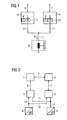
- FIG. 1 In this context is on FIG. 1 referenced, in which a redundant control of an actuator in the form of an inductive load is shown.
- the in the FIGS. 1 and 2 The same parts shown are provided with the same reference numerals.
- the redundantly constructed peripheral units 4, 5 have parallel-connected analog outputs 12, 13, wherein, depending on which redundancy unit operates in master mode, either the output 12 of the peripheral unit 4 or the output 13 of the peripheral unit 5 a current I an actuator 9 ' supplies. In the event that the redundancy unit, to which the peripheral unit 4 is assigned, is active, the peripheral unit 4 supplies the current I to the actuator 9 'via its output 12.
- the redundancy unit including the peripheral unit 5 is passive in this case, whereby the peripheral unit 5 does not supply power to the actuator 9 '.
- the peripheral unit 4 is switched to passive if the peripheral unit 5 transmits the current I to the actuator 9 '.
- FIG. 2 In this context is on FIG. 2 referenced, in which a function diagram of an evaluation algorithm of a peripheral unit is shown.
- a difference generator 14 determines the difference between an actual output current I ist and a desired output current I soll , wherein the amount of this difference determined by an absolute value generator 15 is compared with a predefinable limit value Gw1 of a limit value adjuster 16 over a predefinable time interval ⁇ of a delay element 17.
- an error signal F is generated via an AND or OR gate 23, which indicates to a control computer a fault in an analog output of a peripheral unit.
- the limit value Gw1 is set very small. Even in the event that the rate of change (.DELTA.I is / .DELTA.t) of the actual output current I is substantially not coincident with the rate of change (.DELTA.I soll / .DELTA.t) of the target output current I soll , an error F is displayed to the control computer, This error message indicates that there is a total hardware failure of the analog output of the peripheral unit. This failure can z. B. by a breakage of the line 11 between the peripheral unit 4, 5 and the actuator 9 '( FIG. 1 ).
- the rate of change of the actual output current I is and the target output current I soll detect elements 18, 19, wherein an error signal F via the AND or OR gate 23 is then triggered, if an AND gate 22 detects that, on the one hand, the rate of change of the actual Output current I is negative, this falls below a predetermined limit Gw2 a limit value 19 and on the other hand, substantially at the same time as the change of the actual output current I is no change in the target output current I should have been effected.
- the actuator 9 ' has a very high inductance L as the electromagnetic system.
- a deviation from the nominal and actual output current is not forwarded unfiltered to the control computer, but is first filtered over several time stages. Only when a deviation is longer than the time .DELTA.t, an error message is triggered and causes a change.
Landscapes
- Physics & Mathematics (AREA)
- General Physics & Mathematics (AREA)
- Engineering & Computer Science (AREA)
- Automation & Control Theory (AREA)
- Safety Devices In Control Systems (AREA)
Applications Claiming Priority (2)
| Application Number | Priority Date | Filing Date | Title |
|---|---|---|---|
| DE2003157797 DE10357797A1 (de) | 2003-12-10 | 2003-12-10 | Peripherieeinheit für ein redundantes Steuersystem |
| PCT/EP2004/014116 WO2005057306A1 (de) | 2003-12-10 | 2004-12-10 | Peripherieeinheit für ein redundantes steuersystem |
Publications (2)
| Publication Number | Publication Date |
|---|---|
| EP1692578A1 EP1692578A1 (de) | 2006-08-23 |
| EP1692578B1 true EP1692578B1 (de) | 2008-04-30 |
Family
ID=34672564
Family Applications (1)
| Application Number | Title | Priority Date | Filing Date |
|---|---|---|---|
| EP04803758A Not-in-force EP1692578B1 (de) | 2003-12-10 | 2004-12-10 | Peripherieeinheit für ein redundantes steuersystem |
Country Status (5)
| Country | Link |
|---|---|
| EP (1) | EP1692578B1 (ja) |
| CN (1) | CN100541363C (ja) |
| DE (2) | DE10357797A1 (ja) |
| ES (1) | ES2303651T3 (ja) |
| WO (1) | WO2005057306A1 (ja) |
Families Citing this family (5)
| Publication number | Priority date | Publication date | Assignee | Title |
|---|---|---|---|---|
| DE102007022631B3 (de) * | 2007-05-11 | 2008-12-18 | Phoenix Contact Gmbh & Co. Kg | Parametierungsüberwachung für analoge Signalbaugruppen |
| EP2048555A1 (de) * | 2007-10-01 | 2009-04-15 | Siemens Aktiengesellschaft | Analoge Ausgabeeinheit mit Fehlererkennung |
| DE102009022389A1 (de) * | 2009-05-22 | 2010-12-02 | Phoenix Contact Gmbh & Co. Kg | Steuerungssystem zum Steuern eines Prozesses |
| EP2280326B1 (de) * | 2009-07-09 | 2014-04-16 | Siemens Aktiengesellschaft | Spannungsversorgungsmodul für ein Automatisierungssystem |
| EP3214512B1 (de) * | 2016-03-02 | 2018-04-25 | Siemens Aktiengesellschaft | Redundantes steuersystem für einen aktor und verfahren zu seiner redundanten steuerung |
Family Cites Families (5)
| Publication number | Priority date | Publication date | Assignee | Title |
|---|---|---|---|---|
| FR2703480B1 (fr) * | 1993-03-30 | 1995-06-02 | Merlin Gerin | Interface analogique de sécurité. |
| DE4312305C5 (de) * | 1993-04-15 | 2004-07-15 | Abb Patent Gmbh | Sicherheitsgerichtete speichergrogrammierbare Steuerung |
| ES2118170T3 (es) * | 1993-10-11 | 1998-09-16 | Siemens Ag | Modulo de procesamiento para un sistema de automatizacion modular. |
| DE10008434A1 (de) * | 2000-02-23 | 2001-09-20 | Phoenix Contact Gmbh & Co | Verfahren und Vorrichtung zur Sicherheitsüberwachung einer Steuereinrichtung |
| JP2003217294A (ja) * | 2001-11-16 | 2003-07-31 | Fujitsu Ltd | 半導体記憶装置、及び冗長判定方法 |
-
2003
- 2003-12-10 DE DE2003157797 patent/DE10357797A1/de not_active Withdrawn
-
2004
- 2004-12-10 EP EP04803758A patent/EP1692578B1/de not_active Not-in-force
- 2004-12-10 DE DE502004007013T patent/DE502004007013D1/de active Active
- 2004-12-10 ES ES04803758T patent/ES2303651T3/es active Active
- 2004-12-10 CN CNB2004800415663A patent/CN100541363C/zh not_active Expired - Fee Related
- 2004-12-10 WO PCT/EP2004/014116 patent/WO2005057306A1/de active IP Right Grant
Also Published As
| Publication number | Publication date |
|---|---|
| WO2005057306A1 (de) | 2005-06-23 |
| ES2303651T3 (es) | 2008-08-16 |
| DE10357797A1 (de) | 2005-08-04 |
| DE502004007013D1 (ja) | 2008-06-12 |
| CN1914570A (zh) | 2007-02-14 |
| CN100541363C (zh) | 2009-09-16 |
| EP1692578A1 (de) | 2006-08-23 |
Similar Documents
| Publication | Publication Date | Title |
|---|---|---|
| EP1297394B1 (de) | Redundantes steuerungssystem sowie steuerrechner und peripherieeinheit für ein derartiges steuerungssystem | |
| EP3246771B1 (de) | Verfahren zum betreiben eines redundanten automatisierungssystems | |
| EP2657797B1 (de) | Verfahren zum Betreiben eines redundanten Automatisierungssystems | |
| DE102006047026B4 (de) | Verfahren und System zum redundanten Ansteuern einer Slaveeinrichtung | |
| EP2817682B1 (de) | Verfahren zum ausfallsicheren betreiben eines prozesssteuersystems mit redundanten steuereinrichtungen | |
| EP2857913B1 (de) | Redundantes Automatisierungssystem | |
| DE4317729A1 (de) | Programmierbare Steuereinheit | |
| EP1743225B1 (de) | Redundantes automatisierungssystem umfassend ein master- und ein stand-by-automatisierungsgerät | |
| EP1860564A1 (de) | Verfahren und Vorrichtung zum Austausch von Daten auf Basis des OPC-Kommunikationsprotokolls zwischen redundanten Prozessautomatisierungskomponenten | |
| DE19744071B4 (de) | Eine programmierbare Logiksteuervorrichtung verwendendes Steuerungssystem | |
| EP1092177B1 (de) | Regler bzw. triebwerksregler, triebwerk und verfahren zum regeln eines stell- oder antriebssystems bzw. eines triebwerks | |
| EP1699203A1 (de) | Modulares numerisches Steuergerät | |
| EP1086408B1 (de) | Steuereinrichtung für eine maschine, anlage oder ein gerät, sowie verfahren zum überwachen einer steuerung | |
| EP0791874B1 (de) | Verfahren und Vorrichtung zum Steuern von binären Sensoren und/oder Aktuatoren | |
| EP1619565B1 (de) | Verfahren und Vorrichtung zum sicheren Schalten eines Automatisierungsbussystems | |
| EP1672446B1 (de) | Sichere Eingabe-/Ausgabe-Baugruppen für eine Steuerung | |
| EP1692578B1 (de) | Peripherieeinheit für ein redundantes steuersystem | |
| EP1779206B1 (de) | Peripherieeinheit für ein automatisierungsgerät | |
| EP3214512A1 (de) | Redundantes steuersystem für einen aktor und verfahren zu seiner redundanten steuerung | |
| EP2418580B1 (de) | Verfahren zum Betreiben eines Netzwerkes und Netzwerk | |
| EP1695159B1 (de) | Redundantes steuersystem | |
| EP3161952B1 (de) | Schaltnetzteil mit web-schnittstelle | |
| EP2048555A1 (de) | Analoge Ausgabeeinheit mit Fehlererkennung | |
| EP1566873B1 (de) | Sicherheits-Schaltungsverbund mit Ringkonzept für Steuergeräte der Leistungselektronik | |
| EP1493067B1 (de) | Verfahren zum projektieren und/oder betreiben einer automatisierungseinrichtung |
Legal Events
| Date | Code | Title | Description |
|---|---|---|---|
| PUAI | Public reference made under article 153(3) epc to a published international application that has entered the european phase |
Free format text: ORIGINAL CODE: 0009012 |
|
| 17P | Request for examination filed |
Effective date: 20060609 |
|
| AK | Designated contracting states |
Kind code of ref document: A1 Designated state(s): DE ES FR GB IT |
|
| DAX | Request for extension of the european patent (deleted) | ||
| RBV | Designated contracting states (corrected) |
Designated state(s): DE ES FR GB IT |
|
| GRAP | Despatch of communication of intention to grant a patent |
Free format text: ORIGINAL CODE: EPIDOSNIGR1 |
|
| GRAS | Grant fee paid |
Free format text: ORIGINAL CODE: EPIDOSNIGR3 |
|
| GRAA | (expected) grant |
Free format text: ORIGINAL CODE: 0009210 |
|
| AK | Designated contracting states |
Kind code of ref document: B1 Designated state(s): DE ES FR GB IT |
|
| REG | Reference to a national code |
Ref country code: GB Ref legal event code: FG4D Free format text: NOT ENGLISH |
|
| GBT | Gb: translation of ep patent filed (gb section 77(6)(a)/1977) |
Effective date: 20080430 |
|
| REF | Corresponds to: |
Ref document number: 502004007013 Country of ref document: DE Date of ref document: 20080612 Kind code of ref document: P |
|
| REG | Reference to a national code |
Ref country code: ES Ref legal event code: FG2A Ref document number: 2303651 Country of ref document: ES Kind code of ref document: T3 |
|
| ET | Fr: translation filed | ||
| PLBE | No opposition filed within time limit |
Free format text: ORIGINAL CODE: 0009261 |
|
| STAA | Information on the status of an ep patent application or granted ep patent |
Free format text: STATUS: NO OPPOSITION FILED WITHIN TIME LIMIT |
|
| 26N | No opposition filed |
Effective date: 20090202 |
|
| PGFP | Annual fee paid to national office [announced via postgrant information from national office to epo] |
Ref country code: ES Payment date: 20150127 Year of fee payment: 11 |
|
| REG | Reference to a national code |
Ref country code: FR Ref legal event code: PLFP Year of fee payment: 12 |
|
| REG | Reference to a national code |
Ref country code: FR Ref legal event code: PLFP Year of fee payment: 13 |
|
| REG | Reference to a national code |
Ref country code: ES Ref legal event code: FD2A Effective date: 20170130 |
|
| PGFP | Annual fee paid to national office [announced via postgrant information from national office to epo] |
Ref country code: GB Payment date: 20161212 Year of fee payment: 13 |
|
| PG25 | Lapsed in a contracting state [announced via postgrant information from national office to epo] |
Ref country code: ES Free format text: LAPSE BECAUSE OF NON-PAYMENT OF DUE FEES Effective date: 20151211 |
|
| PGFP | Annual fee paid to national office [announced via postgrant information from national office to epo] |
Ref country code: FR Payment date: 20161221 Year of fee payment: 13 |
|
| PGFP | Annual fee paid to national office [announced via postgrant information from national office to epo] |
Ref country code: DE Payment date: 20170220 Year of fee payment: 13 |
|
| PGFP | Annual fee paid to national office [announced via postgrant information from national office to epo] |
Ref country code: IT Payment date: 20161229 Year of fee payment: 13 |
|
| REG | Reference to a national code |
Ref country code: DE Ref legal event code: R119 Ref document number: 502004007013 Country of ref document: DE |
|
| GBPC | Gb: european patent ceased through non-payment of renewal fee |
Effective date: 20171210 |
|
| REG | Reference to a national code |
Ref country code: FR Ref legal event code: ST Effective date: 20180831 |
|
| PG25 | Lapsed in a contracting state [announced via postgrant information from national office to epo] |
Ref country code: DE Free format text: LAPSE BECAUSE OF NON-PAYMENT OF DUE FEES Effective date: 20180703 Ref country code: IT Free format text: LAPSE BECAUSE OF NON-PAYMENT OF DUE FEES Effective date: 20171210 Ref country code: FR Free format text: LAPSE BECAUSE OF NON-PAYMENT OF DUE FEES Effective date: 20180102 |
|
| PG25 | Lapsed in a contracting state [announced via postgrant information from national office to epo] |
Ref country code: GB Free format text: LAPSE BECAUSE OF NON-PAYMENT OF DUE FEES Effective date: 20171210 |