EP3214512B1 - Redundantes steuersystem für einen aktor und verfahren zu seiner redundanten steuerung - Google Patents
Redundantes steuersystem für einen aktor und verfahren zu seiner redundanten steuerung Download PDFInfo
- Publication number
- EP3214512B1 EP3214512B1 EP16158266.3A EP16158266A EP3214512B1 EP 3214512 B1 EP3214512 B1 EP 3214512B1 EP 16158266 A EP16158266 A EP 16158266A EP 3214512 B1 EP3214512 B1 EP 3214512B1
- Authority
- EP
- European Patent Office
- Prior art keywords
- output
- actuator
- modules
- module
- command
- Prior art date
- Legal status (The legal status is an assumption and is not a legal conclusion. Google has not performed a legal analysis and makes no representation as to the accuracy of the status listed.)
- Active
Links
Images
Classifications
-
- G—PHYSICS
- G05—CONTROLLING; REGULATING
- G05B—CONTROL OR REGULATING SYSTEMS IN GENERAL; FUNCTIONAL ELEMENTS OF SUCH SYSTEMS; MONITORING OR TESTING ARRANGEMENTS FOR SUCH SYSTEMS OR ELEMENTS
- G05B23/00—Testing or monitoring of control systems or parts thereof
- G05B23/02—Electric testing or monitoring
- G05B23/0205—Electric testing or monitoring by means of a monitoring system capable of detecting and responding to faults
- G05B23/0259—Electric testing or monitoring by means of a monitoring system capable of detecting and responding to faults characterized by the response to fault detection
- G05B23/0286—Modifications to the monitored process, e.g. stopping operation or adapting control
-
- G—PHYSICS
- G05—CONTROLLING; REGULATING
- G05B—CONTROL OR REGULATING SYSTEMS IN GENERAL; FUNCTIONAL ELEMENTS OF SUCH SYSTEMS; MONITORING OR TESTING ARRANGEMENTS FOR SUCH SYSTEMS OR ELEMENTS
- G05B9/00—Safety arrangements
- G05B9/02—Safety arrangements electric
- G05B9/03—Safety arrangements electric with multiple-channel loop, i.e. redundant control systems
-
- G—PHYSICS
- G05—CONTROLLING; REGULATING
- G05B—CONTROL OR REGULATING SYSTEMS IN GENERAL; FUNCTIONAL ELEMENTS OF SUCH SYSTEMS; MONITORING OR TESTING ARRANGEMENTS FOR SUCH SYSTEMS OR ELEMENTS
- G05B19/00—Programme-control systems
- G05B19/02—Programme-control systems electric
- G05B19/04—Programme control other than numerical control, i.e. in sequence controllers or logic controllers
- G05B19/05—Programmable logic controllers, e.g. simulating logic interconnections of signals according to ladder diagrams or function charts
- G05B19/052—Linking several PLC's
-
- G—PHYSICS
- G05—CONTROLLING; REGULATING
- G05B—CONTROL OR REGULATING SYSTEMS IN GENERAL; FUNCTIONAL ELEMENTS OF SUCH SYSTEMS; MONITORING OR TESTING ARRANGEMENTS FOR SUCH SYSTEMS OR ELEMENTS
- G05B19/00—Programme-control systems
- G05B19/02—Programme-control systems electric
- G05B19/04—Programme control other than numerical control, i.e. in sequence controllers or logic controllers
- G05B19/05—Programmable logic controllers, e.g. simulating logic interconnections of signals according to ladder diagrams or function charts
- G05B19/058—Safety, monitoring
-
- G—PHYSICS
- G05—CONTROLLING; REGULATING
- G05B—CONTROL OR REGULATING SYSTEMS IN GENERAL; FUNCTIONAL ELEMENTS OF SUCH SYSTEMS; MONITORING OR TESTING ARRANGEMENTS FOR SUCH SYSTEMS OR ELEMENTS
- G05B2219/00—Program-control systems
- G05B2219/20—Pc systems
- G05B2219/24—Pc safety
- G05B2219/24173—One sensor, two I-O channels each for different processor
-
- G—PHYSICS
- G05—CONTROLLING; REGULATING
- G05B—CONTROL OR REGULATING SYSTEMS IN GENERAL; FUNCTIONAL ELEMENTS OF SUCH SYSTEMS; MONITORING OR TESTING ARRANGEMENTS FOR SUCH SYSTEMS OR ELEMENTS
- G05B2219/00—Program-control systems
- G05B2219/20—Pc systems
- G05B2219/24—Pc safety
- G05B2219/24182—Redundancy
Definitions
- the invention relates to a redundant control system according to the preamble of claim 1.
- the invention further relates to a method for the redundant control of an actuator according to the preamble of claim 5.
- SIMATIC PCS 7 from Siemens are used to automate processes in technical plants and are usually structured hierarchically through several levels.
- the states of the technical process (sensors) or the process are specifically influenced (actuators) by means of field devices.
- control computers programmable logic controllers with CPU units
- field-level control functions taking input values from the sensors, e.g. As a pressure transmitter, received and output values to the actuators, eg. B. a positioner for a control valve deliver.
- the master control and regulation of the process takes place in master computers.
- a peripheral station consists of an interface module (head module) for connection to the fieldbus and a number of I / O modules (digital and analog input and output modules) for connecting the field devices.
- the peripheral modules can have one or more channels, to each of which a field device can be connected.
- a highly available system as for example from the aforementioned WO 2005/057306 A1 or the DE 10 2004 034 451 A1 is known, has redundant central functions and is constructed with two separate control computers.
- the two control computers In so-called "hot stand-by" mode, the two control computers simultaneously operate the same control program in the undisturbed case, but only one control computer is active and controls the process with its output values. In the event of a fault, the intact control computer alone takes over the control of the process.
- the output values of the two control computers are supplied to the actuator via separate output modules, wherein, like the DE 10 2004 034 451 A1 shows decoupling diodes at the signal outputs of the output modules in case of an OR operation of digital output values or an addition of analog output values.
- a redundancy coupling is provided, via which the control computer are connected to each other.
- the first control computer via a first bus with an interface module of a first peripheral station, z. B. ET200M from Siemens, which contains at least one peripheral module.
- the second redundant control computer is connected via a second bus to an interface module of a second peripheral station, which also contains at least one peripheral module.
- the actuator is arranged at signal outputs of two peripheral modules, which form output modules and are arranged in different peripheral stations.
- Each of the interface modules of the two peripheral stations is designed to output values obtained via the bus from the respective control computer for the actuator to the respective output module for output to hand over the actor.
- Each of the output modules is configured to detect a fault at its signal output and to display to the control computer to enable a switch to the undisturbed peripheral unit.
- the EP 0 478 288 A2 discloses a redundant automation system for an actuator which is connected to decoupled signal outputs from two output modules. Both output modules are connected via a common bus with two redundant control computers.
- a redundant automation system for a sensor is known, which is connected redundantly to two peripheral units arranged in different peripheral stations. Both peripheral stations each contain an interface module, with which they are connected via a common bus to an automation device.
- a redundant automation system for sensors and actuators is known, which are connected to a peripheral station.
- the peripheral station is connected via a bus to two subsystems, eg. As automation equipment, connected, as well as from the above DE 10 2004 034 451 A1 or WO 2005/057306 A1 known, cyclically and synchronously execute the same control program and are connected to each other via a synchronization connection. Again, only one subsystem is active, which is switched to the other subsystem in case of error. To prevent the changeover from interfering with the process to be controlled, a dead time may occur at the outputs of the connected I / O during which the outputs remain at their last valid process output values.
- a problem for the redundancy operation results from the determination of a specific reaction of the system when a device upstream of the output module such.
- such fieldbus-side disturbance or such a failure of the interface module of the peripheral station are detected to subsequently cause all output modules of the peripheral station by means of a command (command "Output Disable") to freeze the last received output values.
- the actuator In the case of the analog output, the actuator then receives the sum of the frozen and the current output value and, in the case of the digital output, the logical value "one" in the unfavorable case.
- the established reaction mechanism therefore leads to a complete redundancy failure.
- One way to solve the problem is to place in each of the two peripheral stations an additional digital output subassembly as an auxiliary subassembly, which, upon receipt of the "Output Disable" command, drives an external switching relay to disconnect the redundant power output device from the power supply.
- the signal output of the output module is forcibly brought into a currentless and de-energized state, which can not influence the output value supplied by the other redundant output module via the OR operation.
- the substitute value may be, in particular, the last-received output value, but also another parameterizable value that can be differentiated from the operational output values.
- the output modules of the redundant control system according to the invention may equally be digital or analog output modules.
- the restriction applies to implement a command to output a replacement value only if the other output module has also received such a command, only for the channels on which the actuator via the Diodes is connected.
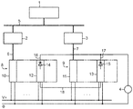
- the field level contains further, not shown here field devices that detect the states of a technical process in the form of sensors and designed as actuators affect the process targeted.
- the guide device 1 and the control computers 2, 3 are connected to each other via a system bus 5 (eg, Ethernet).
- the two control computers 2, 3 each operate in redundant operation from one and the same control or user program, wherein they inter alia via separate digital fieldbuses 6, 7 (eg PROFIBUS DP) process received input values from sensors.
- the connection of the field devices to the field buses 6, 7 of the two control computers 2, 3 is carried out by a first and a second decentralized peripheral station 8, 9.
- Each of the two peripheral stations 8, 9 consists of an interface module (head assembly) 10, 11 for connection to the respective field bus 6, 7 and a number of single or multi-channel peripheral modules, of which only one output module 12, 13 is shown here.
- the actuator 4 is connected via decoupling diodes 14, 15 to the signal outputs 16, 17 of the two output modules 12, 13.
- the interface modules 10, 11 transfer output values, which they receive from the respective control computer 2, 3 for the actuator 4, to the output module 12, 13, wherein the diodes 14, 15 for the actuator 4 disjunctively (OR) link digital values and analog values Add (streams). Both output modules 12, 13 are active. You will both receive the same output values in error-free redundancy mode.
- the two control computers 2, 3 equalize themselves accordingly.
- the interface modules 10, 11 each monitor the fieldbus 6, 7, to which they are connected, and in the event of a fault, z. B. in case of failure of the control computer (eg STOP mode, pulled cable, etc.) to all output modules of the relevant peripheral station 8, 9 an instruction to output replacement values, for example in the form of the last received output values.
- This behavior is necessary in non-redundant operation. In redundant operation, however, this leads to a faulty operating state.
- the output module 12, 13 supplying the actuator 4 redundantly with output values therefore only converts this command if and as long as both of them receive such an instruction. To enable this, they exchange information about receiving a replacement value command via a communication link (eg RS485). This prevents the actuator 4 z. B. instead of a current analog output value receives the sum of this and an output value frozen to the command.
Description
- Die Erfindung betrifft ein redundantes Steuersystem gemäß dem Oberbegriff des Anspruchs 1.
- Die Erfindung betrifft ferner ein Verfahren zur redundanten Steuerung eines Aktors entsprechend dem Oberbegriff des Anspruchs 5.
- Ein derartiges Steuersystem und Verfahren sind aus der
WO 2005/057306 A1 bekannt. - Prozessleitsysteme wie z. B. SIMATIC PCS 7 von Siemens dienen zur Automatisierung von Prozessen in technischen Anlagen und sind üblicherweise hierarchisch durch mehrere Ebenen strukturiert. Auf der Feldebene werden mittels Feldgeräten die Zustände des technischen Prozesses erfasst (Sensoren) bzw. der Prozess gezielt beeinflusst (Aktoren). In der Steuerungsebene führen Steuerrechner (speicherprogrammierbare Steuerungen mit CPU-Einheiten) feldnahe Steuerungs- und Regelungsfunktionen aus, wobei sie Eingabewerte von den Sensoren, z. B. einem Druckmessumformer, empfangen und Ausgabewerte an die Aktoren, z. B. einen Stellungsregler für ein Regelventil, abgeben. Auf der Prozessführungsebene findet in Leitrechnern die übergeordnete Steuerung und Regelung des Prozesses statt.
- Der Datenaustausch zwischen den Feldgeräten und den Steuerrechnern erfolgt üblicherweise über einen digitalen Feldbus, wie z. B. PROFIBUS DP oder PROFINET. Da die Feldgeräte normalerweise selbst keinen entsprechenden Feldbusanschluss aufweisen, werden sie über dezentrale Peripheriestationen an den Feldbus angebunden. Eine Peripheriestation besteht aus einem Interfacemodul (Kopfbaugruppe) zum Anschluss an den Feldbus und einer Anzahl von Peripheriebaugruppen (digitale und analoge Ein- und Ausgabebaugruppen) zum Anschluss der Feldgeräte. Die Peripheriebaugruppen können einen oder mehrere Kanäle aufweisen, an denen jeweils ein Feldgerät angeschlossen werden kann.
- Ein hochverfügbares System, wie es beispielsweise aus der eingangs erwähnten
WO 2005/057306 A1 oder derDE 10 2004 034 451 A1 bekannt ist, besitzt redundant ausgelegte zentrale Funktionen und ist mit zwei getrennten Steuerrechnern aufgebaut. Beim so genannten "Hot Stand By"-Betrieb arbeiten die beiden Steuerrechner im ungestörten Fall gleichzeitig dasselbe Steuerprogramm ab, wobei jedoch nur ein Steuerrechner aktiv ist und mit seinen Ausgabewerten den Prozess steuert. Im Fehlerfall übernimmt der intakte Steuerrechner allein die Steuerung des Prozesses. Die Ausgabewerte der beiden Steuerrechner werden dem Aktor über separate Ausgangsbaugruppen zugeführt, wobei, wie dieDE 10 2004 034 451 A1 zeigt, Entkopplungsdioden an den Signalausgängen der Ausgangsbaugruppen im Falle eine ODER-Verknüpfung digitaler Ausgabewerte bzw. eine Addition analoger Ausgabewerte bewirken. Zum Austausch von Informationen, z. B. in Form von Status- und Abgleichinformationen, ist eine Redundanzkopplung vorgesehen, über welche die Steuerrechner miteinander verbunden sind. - Bei dem aus der
WO 2005/057306 A1 bekannten redundanten Steuersystem ist der erste Steuerrechner über einen ersten Bus mit einem Interfacemodul einer ersten Peripheriestation, z. B. ET200M von Siemens, verbunden, welche mindestens eine Peripheriebaugruppe enthält. Der zweite redundante Steuerrechner ist über einen zweiten Bus mit einem Interfacemodul einer zweiten Peripheriestation verbunden, die ebenfalls mindestens eine Peripheriebaugruppe enthält. Der Aktor ist an Signalausgängen von zwei Peripheriebaugruppen angeordnet, die Ausgabebaugruppen bilden und in unterschiedlichen Peripheriestationen angeordnet sind. Jedes der Interfacemodule der beiden Peripheriestationen ist dazu ausgebildet, über den Bus von dem jeweiligen Steuerrechner für den Aktor erhaltene Ausgabewerte an die jeweilige Ausgabebaugruppe zur Ausgabe an den Aktor zu übergeben. Jede der Ausgabebaugruppen ist dazu ausgebildet, eine Störung an ihrem Signalausgang zu erkennen und dem Steuerrechner anzuzeigen, um eine Umschaltung auf die ungestörte Peripherieeinheit zu ermöglichen. - Die
EP 0 478 288 A2 offenbart ein redundantes Automatisierungssystem für einen Aktor, der an voneinander entkoppelten Signalausgängen von zwei Ausgabebaugruppen angeschlossen ist. Beide Ausgabebaugruppen sind über einen gemeinsamen Bus mit zwei redundanten Steuerrechnern verbunden. - Aus der
EP 2 806 316 A1 ist ein redundantes Automatisierungssystem für einen Sensor bekannt, der redundant an zwei in unterschiedlichen Peripheriestationen angeordneten Peripheriebaugruppen angeschlossen ist. Beide Peripheriestationen enthalten jeweils ein Interfacemodul, mit dem sie über einen gemeinsamen Bus an einem Automatisierungsgerät angeschlossen sind. - Aus der
EP 2 799 947 A1 ist eine Anordnung mit einer Redundanz-Adaptereinheit bekannt, um ein Feldgerät, z. B. Aktor, redundant an zwei in unterschiedlichen Peripheriestationen angeordneten Peripheriebaugruppen anzuschließen. - Aus der
EP 2 860 598 A1 ist ein redundantes Automatisierungssystem für Sensoren und Aktoren bekannt, die an einer Peripheriestation angeschlossen sind. Die Peripheriestation ist über einen Bus an zwei Teilsystemen, z. B. Automatisierungsgeräte, angeschlossen, die, wie auch aus der oben genanntenDE 10 2004 034 451 A1 oderWO 2005/057306 A1 bekannt, zyklisch und synchron dasselbe Steuerprogramm abarbeiten und dazu über eine Synchronisationsverbindung miteinander verbunden sind. Auch hier ist nur ein Teilsystem aktiv, wobei im Fehlerfall auf das andere Teilsystem umgeschaltet wird. Damit sich die Umschaltung nicht störend auf den zu steuernden Prozess auswirkt, darf an den Ausgängen der angeschlossenen Peripherie eine Totzeit auftreten, während der die Ausgänge auf ihren zuletzt gültigen Prozessausgangswerten verharren. - Ein Problem für den Redundanzbetrieb ergibt sich durch die Festlegung einer bestimmten Reaktion des Systems, wenn eine der Ausgabebaugruppe vorgelagerte Einrichtung wie z. B. der Steuerrechner oder der Feldbus gestört ist oder ausfällt. In einem PCS7-System werden eine solche feldbusseitige Störung bzw. ein solcher Ausfall von dem Interfacemodule der Peripheriestation detektiert, um in der Folge alle Ausgabebaugruppen der Peripheriestation mittels eines Befehls (Kommando "Output Disable") dazu zu veranlassen, die zuletzt erhaltenen Ausgabewerte einzufrieren. Dies führt bei dem oben beschriebenen Redundanzbetrieb mit zwei Steuerrechnern und zwei dezentralen Peripheriestationen dazu, dass bei einer Störung des bis dahin aktiven Steuerrechners der von ihm zuletzt ausgegebene Ausgabewert an dem Signalausgang der nachgeordneten Ausgangsbaugruppe gehalten wird, während die dem bisher inaktiven und jetzt aktiven Steuerrechner nachgeordnete Ausgangsbaugruppe die aktuellen Ausgabewerte ausgibt. Bei der Analogausgabe erhält der Aktor dann die Summe aus dem eingefrorenen und dem aktuellen Ausgabewert und bei der Digitalausgabe im ungünstigen Fall dauerhaft der logischen Wert "eins". Der festgelegte Reaktionsmechanismus führt daher zu einem kompletten Redundanzausfall.
- Eine Möglichkeit zur Lösung des Problems besteht darin, in jeder der beiden Peripheriestationen eine zusätzliche Digitalausgabebaugruppen als Hilfsbaugruppe anzuordnen, die bei Erhalt des Befehls "Output Disable" ein externes Schaltrelais ansteuert, um die für den Redundanzbetrieb vorgesehene Ausgabebaugruppe von der Stromversorgung abzuschalten. Dadurch wird der Signalausgang der Ausgabebaugruppe zwangsweise in einen strom- und spannungslosen Zustand gebracht, welcher den von der anderen redundanten Ausgabebaugruppe gelieferten Ausgabewert über die ODER-Verknüpfung nicht beeinflussen kann.
- Zwar wird das Problem mit dieser Maßnahme, wenn auch mit erhöhtem Aufwand, gelöst, jedoch ergibt sich als Nachteil, dass sich die redundanten Ausgabebaugruppen bei Wegnahme ihrer Stromversorgung relativ lange unkontrollierbar und undefiniert verhalten, so dass eine schnelle Umschaltung auf die jeweils andere redundante Ausgangsbaugruppe nicht möglich ist.
- Gemäß der Erfindung wird das oben geschilderte Problem aufwandsarm durch das in Anspruch 1 angegebene redundante Steuersystem und das in Anspruch 5 angegebene Verfahren gelöst, die beide jeweils auch eine schnelle Umschaltung zwischen den redundanten Ausgangsbaugruppen ermöglichen.
- Gegenstand der Erfindung ist somit ein redundantes Steuersystem
- mit einem Aktor,
- mit einem ersten Steuerrechner, der über einen ersten Bus mit einem Interfacemodul einer ersten Peripheriestation verbunden ist, welche mindestens eine Peripheriebaugruppe enthält, und
- mit einem zweiten redundanten Steuerrechner, der über einen zweiten Bus mit einem Interfacemodul einer zweiten Peripheriestation verbunden ist, die ebenfalls mindestens eine Peripheriebaugruppe enthält, wobei
- der Aktor an voneinander entkoppelten Signalausgängen von zwei jeweils eine Ausgabebaugruppe bildenden Peripheriebaugruppen der beiden Peripheriestationen angeschlossen ist und
- jedes der Interfacemodule dazu ausgebildet ist, über den Bus von dem jeweiligen Steuerrechner für den Aktor erhaltene Ausgabewerte an die Ausgabebaugruppe zur Ausgabe an den Aktor zu übergeben
- jedes der Interfacemodule ferner dazu ausgebildet ist, bei Detektion einer busseitigen Störung an die Ausgabebaugruppe und an alle weiteren Ausgabebaugruppen der Peripheriestation einen Befehl zur Ausgabe von Ersatzwerten an ihren Signalausgängen zu übermitteln, und
- die beiden Ausgabebaugruppen, an deren Signalausgängen der Aktor angeschlossen ist, über eine Kommunikationsverbindung miteinander verbunden und dazu ausgebildet sind, Informationen über den Erhalt eines Befehls zur Ausgabe eines Ersatzwertes auszutauschen und diesen Befehl nur dann umzusetzen, wenn die jeweils andere Ausgabebaugruppe ebenfalls einen solchen Befehl erhalten hat.
- Gegenstand der Erfindung ist ferner ein Verfahren zur redundanten Steuerung eines Aktors in einem Steuersystem, in dem
- ein erster Steuerrechner über einen ersten Bus mit einem Interfacemodul einer ersten Peripheriestation verbunden ist, welche mindestens eine Peripheriebaugruppe enthält,
- ein zweiter redundanter Steuerrechner über einen zweiten Bus mit einem Interfacemodul einer zweiten Peripheriestation verbunden ist, die ebenfalls mindestens eine Peripheriebaugruppe enthält, und
- der Aktor an voneinander entkoppelten Signalausgängen von zwei jeweils eine Ausgabebaugruppe bildenden Peripheriebaugruppen der beiden Peripheriestationen angeschlossen ist, wobei
- jedes der Interfacemodule über den Bus von dem jeweiligen Steuerrechner für den Aktor erhaltene Ausgabewerte an die Ausgabebaugruppe zur Ausgabe an den Aktor übergibt,
- jedes der Interfacemodule bei Detektion einer busseitigen Störung an die Ausgabebaugruppe und an alle weiteren Ausgabebaugruppen der Peripheriestation einen Befehl zur Ausgabe von Ersatzwerten an ihren Signalausgängen übermittelt, und
- die beiden Ausgabebaugruppen an deren Signalausgängen der Aktor angeschlossen ist, über eine Kommunikationsverbindung Informationen über den Erhalt eines Befehls zur Ausgabe eines Ersatzwertes austauschen und diesen Befehl nur dann umzusetzen, wenn auch die jeweils andere Ausgabebaugruppe einen solchen Befehl erhalten hat.
- Bei dem Ersatzwert kann es sich insbesondere um den zuletzt erhaltenen Ausgabewert, aber auch um einen anderen, von den betriebsmäßigen Ausgabewerten unterscheidbaren parametrierbaren Wert handeln.
- Bei den Ausgabebaugruppen des erfindungsgemäßen redundanten Steuersystems kann es sich gleichermaßen um digitale oder analoge Ausgabebaugruppen handeln.
- Für den Fall, dass die beiden redundanten Ausgabebaugruppen mehrkanalig aufgebaut sind, gilt die Einschränkung, einen Befehl zur Ausgabe eines Ersatzwertes nur dann umzusetzen, wenn die jeweils andere Ausgabebaugruppe ebenfalls einen solchen Befehl erhalten hat, nur für die Kanäle, an denen der Aktor über die Dioden angeschlossen ist.
- Zur weiteren Erläuterung der Erfindung wird im Folgenden auf die einzige Figur der Zeichnung Bezug genommen, die in schematischer Blockdarstellung ein Ausführungsbeispiel des erfindungsgemäßen redundanten Steuersystems zeigt.
- Dargestellt ist ein Ausschnitt aus einem Prozessleitsystem mit einer Leiteinrichtung 1 in einer Prozessführungsebene, einem ersten und zweiten Steuerrechner 2, 3 in Form von speicherprogrammierbaren Steuerungen in einer Steuerungsebene sowie einem Aktor 4 auf Feldebene. Die Feldebene enthält weitere, hier nicht gezeigte Feldgeräte, die in Form von Sensoren die Zustände eines technischen Prozesses erfassen und als Aktoren ausgebildet den Prozess gezielt beeinflussen. Die Leiteinrichtung 1 und die Steuerrechner 2, 3 sind über einen Anlagenbus 5 (z. B. Ethernet) miteinander verbunden. Zur Erzeugung von Ausgabewerten für den Aktor 4 arbeiten die beiden Steuerrechner 2, 3 im Redundanzbetrieb jeweils ein und dasselbe Steuer- oder Anwenderprogramm ab, wobei sie u. a. über separate digitale Feldbusse 6, 7 (z. B. PROFIBUS DP) erhaltene Eingabewerte von Sensoren verarbeiten. Die Anbindung der Feldgeräte an die Feldbusse 6, 7 der beiden Steuerrechner 2, 3 erfolgt durch eine erste und eine zweite dezentrale Peripheriestation 8, 9. Jede der beiden Peripheriestationen 8, 9 besteht aus einem Interfacemodul (Kopfbaugruppe) 10, 11 zum Anschluss an den jeweiligen Feldbus 6, 7 und einer Anzahl von ein- oder mehrkanaligen Peripheriebaugruppen, von denen hier nur jeweils eine Ausgabebaugruppe 12, 13 dargestellt ist. Der Aktor 4 ist über Entkopplungsdioden 14, 15 an den Signalausgängen 16, 17 der beiden Ausgabebaugruppen 12, 13 angeschlossen. Die Interfacemodule 10, 11 übergeben Ausgabewerte, die sie von dem jeweiligen Steuerrechner 2, 3 für den Aktor 4 erhalten, an die Ausgabebaugruppe 12, 13, wobei die Dioden 14, 15 für den Aktor 4 digitale Werte disjunktiv (ODER) verknüpfen und analoge Werte (Ströme) addieren. Beide Ausgabebaugruppen 12, 13 sind aktiv. Sie erhalten im fehlerfreien Redundanzbetrieb beide dieselben Ausgabewerte. Die beiden Steuerrechner 2, 3 gleichen sich selbst entsprechend ab.
- Die Interfacemodule 10, 11 überwachen jeweils den Feldbus 6, 7, an den sie angeschlossen sind, und geben im Falle einer Störung, z. B. bei Ausfall des Steuerrechners (z. B. Betriebszustand STOPP, Kabel gezogen, usw.) an alle Ausgabebaugruppen der betreffenden Peripheriestation 8, 9 einen Befehl zur Ausgabe von Ersatzwerten, beispielsweise in Form der zuletzt erhaltenen Ausgabewerte. Dieses Verhalten ist im nicht redundanten Betrieb notwendig. Im redundanten Betrieb führt dies jedoch zu einem fehlerhaften Betriebszustand. Die den Aktor 4 redundant mit Ausgabewerten versorgenden Ausgabebaugruppe 12, 13 setzen daher diesen Befehl nur dann um, wenn und solange sie beide einen solchen Befehl erhalten. Um dies zu ermöglichen, tauschen sie über eine Kommunikationsverbindung (z. B. RS485) Informationen über den Erhalt eines Befehls zur Ausgabe eines Ersatzwertes aus. Dadurch wird verhindert, dass der Aktor 4 z. B. anstelle eines aktuellen analogen Ausgabewertes die Summe aus diesem und einem auf den Befehl hin eingefrorenen Ausgabewert erhält.
Claims (6)
- Redundantes Steuersystem- mit einem Aktor (4),- mit einem ersten Steuerrechner (2), der über einen ersten Bus (6) mit einem Interfacemodul (10) einer ersten Peripheriestation (8) verbunden ist, welche mindestens eine Peripheriebaugruppe enthält, und- mit einem zweiten redundanten Steuerrechner (3), der über einen zweiten Bus (7) mit einem Interfacemodul (11) einer zweiten Peripheriestation (9) verbunden ist, die ebenfalls mindestens eine Peripheriebaugruppe enthält, wobei- der Aktor (4) an voneinander entkoppelten Signalausgängen (16, 17) von zwei jeweils eine Ausgabebaugruppe (12, 13) bildenden Peripheriebaugruppen der beiden Peripheriestationen (8, 9) angeschlossen ist und- jedes der Interfacemodule (10, 11) dazu ausgebildet ist, über den Bus (6, 7) von dem jeweiligen Steuerrechner (2, 3) für den Aktor (4) erhaltene Ausgabewerte an die Ausgabebaugruppe (12, 13) zur Ausgabe an den Aktor (4) zu übergeben,dadurch gekennzeichnet, dass- jedes der Interfacemodule (10, 11) ferner dazu ausgebildet ist, bei Detektion einer busseitigen Störung an die Ausgabebaugruppe (12, 13) und an alle weiteren Ausgabebaugruppen der Peripheriestation (8, 9) einen Befehl zur Ausgabe von Ersatzwerten an ihren Signalausgängen (16, 17) zu übermitteln, und- die beiden Ausgabebaugruppen (12, 13), an deren Signalausgängen (16, 17) der Aktor (4) angeschlossen ist, über eine Kommunikationsverbindung (18) miteinander verbunden und dazu ausgebildet sind, Informationen über den Erhalt eines Befehls zur Ausgabe eines Ersatzwertes auszutauschen und diesen Befehl nur dann umzusetzen, wenn die jeweils andere Ausgabebaugruppe ebenfalls einen solchen Befehl erhalten hat.
- Redundantes Steuersystem nach Anspruch 1, dadurch gekennzeichnet, dass die beiden Ausgabebaugruppen (12, 13) digitale Ausgabebaugruppen sind.
- Redundantes Steuersystem nach Anspruch 1, dadurch gekennzeichnet, dass die beiden Ausgabebaugruppen (12, 13) analoge Ausgabebaugruppen sind.
- Redundantes Steuersystem nach einem der vorangehenden Ansprüche, dadurch gekennzeichnet, dass bei mehrkanaligem Aufbau der Ausgabebaugruppen (12, 13) diese dazu ausgebildet sind, einen zur Ausgabe eines Ersatzwertes erhaltenen Befehl nur für die Kanäle, an deren Signalausgängen der Aktor (4) angeschlossen ist, mit der Einschränkung umzusetzen, dass auch die andere Ausgabebaugruppe einen solchen Befehl erhalten hat.
- Verfahren zur redundanten Steuerung eines Aktors (4) in einem Steuersystem, in dem- ein erster Steuerrechner (2) über einen ersten Bus (6) mit einem Interfacemodul (10) einer ersten Peripheriestation (8) verbunden ist, welche mindestens eine Peripheriebaugruppe enthält,- ein zweiter redundanter Steuerrechner (3) über einen zweiten Bus (7) mit einem Interfacemodul (11) einer zweiten Peripheriestation (9) verbunden ist, die ebenfalls mindestens eine Peripheriebaugruppe enthält, und- der Aktor (4) an voneinander entkoppelten Signalausgängen (16, 17) von zwei jeweils eine Ausgabebaugruppe (12, 13) bildenden Peripheriebaugruppen der beiden Peripheriestationen (8, 9) angeschlossen ist, wobei- jedes der Interfacemodule (10, 11) über den Bus (6, 7) von dem jeweiligen Steuerrechner (2, 3) für den Aktor (4) erhaltene Ausgabewerte an die Ausgabebaugruppe (12, 13) zur Ausgabe an den Aktor (4) übergibt,dadurch gekennzeichnet, dass- jedes der Interfacemodule (10, 11) bei Detektion einer busseitigen Störung an die Ausgabebaugruppe (12, 13) und an alle weiteren Ausgabebaugruppen der Peripheriestation (8, 9) einen Befehl zur Ausgabe von Ersatzwerten an ihren Signalausgängen (16, 17) übermittelt, und- die beiden Ausgabebaugruppen (12, 13), an deren Signalausgängen (16, 17) der Aktor (4) angeschlossen ist, über eine Kommunikationsverbindung (18) Informationen über den Erhalt eines Befehls zur Ausgabe eines Ersatzwertes austauschen und diesen Befehl nur dann umsetzen, wenn auch die jeweils andere Ausgabebaugruppe einen solchen Befehl erhalten hat.
- Verfahren nach Anspruch 5, dadurch gekennzeichnet, dass bei mehrkanaligem Aufbau der Ausgabebaugruppen (12, 13) diese einen zur Ausgabe eines Ersatzwertes erhaltenen Befehl nur für die Kanäle, an deren Signalausgängen der Aktor (4) angeschlossen ist, mit der Einschränkung umsetzen, dass auch die andere Ausgabebaugruppe einen solchen Befehl erhalten hat.
Priority Applications (3)
| Application Number | Priority Date | Filing Date | Title |
|---|---|---|---|
| EP16158266.3A EP3214512B1 (de) | 2016-03-02 | 2016-03-02 | Redundantes steuersystem für einen aktor und verfahren zu seiner redundanten steuerung |
| CN201710119597.5A CN107153351B (zh) | 2016-03-02 | 2017-03-01 | 作动器的冗余控制系统以及用于其冗余控制的方法 |
| US15/446,672 US10386832B2 (en) | 2016-03-02 | 2017-03-01 | Redundant control system for an actuator and method for redundant control thereof |
Applications Claiming Priority (1)
| Application Number | Priority Date | Filing Date | Title |
|---|---|---|---|
| EP16158266.3A EP3214512B1 (de) | 2016-03-02 | 2016-03-02 | Redundantes steuersystem für einen aktor und verfahren zu seiner redundanten steuerung |
Publications (2)
| Publication Number | Publication Date |
|---|---|
| EP3214512A1 EP3214512A1 (de) | 2017-09-06 |
| EP3214512B1 true EP3214512B1 (de) | 2018-04-25 |
Family
ID=55453085
Family Applications (1)
| Application Number | Title | Priority Date | Filing Date |
|---|---|---|---|
| EP16158266.3A Active EP3214512B1 (de) | 2016-03-02 | 2016-03-02 | Redundantes steuersystem für einen aktor und verfahren zu seiner redundanten steuerung |
Country Status (3)
| Country | Link |
|---|---|
| US (1) | US10386832B2 (de) |
| EP (1) | EP3214512B1 (de) |
| CN (1) | CN107153351B (de) |
Families Citing this family (4)
| Publication number | Priority date | Publication date | Assignee | Title |
|---|---|---|---|---|
| DE102017109865A1 (de) * | 2017-05-08 | 2018-11-08 | Webasto SE | Verfahren zur Übermittlung mindestens eines Steuerbefehls und Steuereinrichtung |
| CN107738739B (zh) * | 2017-09-14 | 2019-04-09 | 北京精密机电控制设备研究所 | 一种离合器及基于离合器实现的并联冗余机电作动器 |
| CN107977289B (zh) * | 2017-11-07 | 2020-10-23 | 北京控制工程研究所 | 一种热备份计算机中多模冗余总线容错架构及其控制方法 |
| EP3936949A1 (de) * | 2020-07-09 | 2022-01-12 | Siemens Aktiengesellschaft | Verfahren zum betreiben eines redundanten automatisierungssystems und redundantes automatisierungssystem |
Family Cites Families (21)
| Publication number | Priority date | Publication date | Assignee | Title |
|---|---|---|---|---|
| US4872106A (en) * | 1983-04-06 | 1989-10-03 | New Forney Corp. | Industrial process control system with back-up data processors to take over from failed primary data processors |
| FR2600437B1 (fr) * | 1986-06-18 | 1993-12-31 | Telemecanique Electrique | Procede et dispositif pour la commande redondante d'un organe de puissance |
| US4958270A (en) * | 1989-01-23 | 1990-09-18 | Honeywell Inc. | Method for control data base updating of a redundant processor in a process control system |
| US5202822A (en) | 1990-09-26 | 1993-04-13 | Honeywell Inc. | Universal scheme of input/output redundancy in a process control system |
| AU2003250281A1 (en) * | 2002-07-04 | 2004-01-23 | All-Russian Research Institute Of Automatics | Device for determining the rotational speed of a rotating machine part using redundant sensors and evaluation circuits |
| DE10357797A1 (de) * | 2003-12-10 | 2005-08-04 | Siemens Ag | Peripherieeinheit für ein redundantes Steuersystem |
| DE10358989A1 (de) * | 2003-12-16 | 2005-08-04 | Siemens Ag | Redundantes Steuersystem |
| DE102004034451A1 (de) | 2004-07-16 | 2006-02-16 | Siemens Ag | Redundantes Steuersystem |
| WO2007018651A1 (en) * | 2005-08-05 | 2007-02-15 | Honeywell International, Inc. | Method for redunancy management of distributed and recoverable digital control system |
| DE102009007215A1 (de) * | 2009-02-03 | 2010-08-05 | Siemens Aktiengesellschaft | Automatisierungssystem mit einem programmierbaren Matrixmodul |
| JP5590955B2 (ja) * | 2010-04-26 | 2014-09-17 | ナブテスコ株式会社 | アクチュエータ制御システム |
| DE102012003242A1 (de) * | 2012-02-20 | 2013-08-22 | Phoenix Contact Gmbh & Co. Kg | Verfahren zum ausfallsicheren Betreiben eines Prozesssteuersystems mit redundanten Steuereinrichtungen |
| US9631645B2 (en) * | 2013-02-27 | 2017-04-25 | Woodward, Inc. | Rotary piston actuator anti-rotation configurations |
| US9593696B2 (en) * | 2013-02-27 | 2017-03-14 | Woodward, Inc. | Rotary piston type actuator with hydraulic supply |
| US9697096B2 (en) * | 2013-03-14 | 2017-07-04 | Fts Computertechnik Gmbh | Method for limiting the risk of errors in a redundant, safety-related control system for a motor vehicle |
| EP2799947B1 (de) | 2013-05-03 | 2016-03-23 | Siemens Aktiengesellschaft | Anordnung mit einem ersten und einem zweiten Peripheriegerät |
| EP2806316B1 (de) * | 2013-05-24 | 2017-07-05 | Siemens Aktiengesellschaft | Verfahren zum Betreiben eines Automatisierungssystems |
| EP2860598B1 (de) | 2013-10-14 | 2018-03-21 | Siemens Aktiengesellschaft | Verfahren zum Betreiben eines redundanten Automatisierungssystems, wobei der Slave Diagnosefunktionen durchführt |
| US10042330B2 (en) * | 2014-05-07 | 2018-08-07 | Honeywell International Inc. | Redundant process controllers for segregated supervisory and industrial control networks |
| FR3024925B1 (fr) * | 2014-08-14 | 2016-08-26 | Zodiac Aero Electric | Systeme et procede de commande d'au moins un organe de puissance, notamment pour aeronef |
| US9990286B1 (en) * | 2017-05-05 | 2018-06-05 | Honeywell International, Inc. | Memory tracking using copy-back cache for 1:1 device redundancy |
-
2016
- 2016-03-02 EP EP16158266.3A patent/EP3214512B1/de active Active
-
2017
- 2017-03-01 CN CN201710119597.5A patent/CN107153351B/zh active Active
- 2017-03-01 US US15/446,672 patent/US10386832B2/en active Active
Non-Patent Citations (1)
| Title |
|---|
| None * |
Also Published As
| Publication number | Publication date |
|---|---|
| CN107153351B (zh) | 2020-10-09 |
| EP3214512A1 (de) | 2017-09-06 |
| US20170255191A1 (en) | 2017-09-07 |
| US10386832B2 (en) | 2019-08-20 |
| CN107153351A (zh) | 2017-09-12 |
Similar Documents
| Publication | Publication Date | Title |
|---|---|---|
| DE102006047026B4 (de) | Verfahren und System zum redundanten Ansteuern einer Slaveeinrichtung | |
| EP2981868B1 (de) | Steuer- und datenübertragungsanlage, prozesseinrichtung und verfahren zur redundanten prozesssteuerung mit dezentraler redundanz | |
| EP2504740B1 (de) | Sicherheitsmodul für ein automatisierungsgerät | |
| EP3170287B1 (de) | Steuer- und datenübertragungssystem, gateway-modul, e/a-modul und verfahren zur prozesssteuerung | |
| EP2817682B1 (de) | Verfahren zum ausfallsicheren betreiben eines prozesssteuersystems mit redundanten steuereinrichtungen | |
| EP3214512B1 (de) | Redundantes steuersystem für einen aktor und verfahren zu seiner redundanten steuerung | |
| EP1860564A1 (de) | Verfahren und Vorrichtung zum Austausch von Daten auf Basis des OPC-Kommunikationsprotokolls zwischen redundanten Prozessautomatisierungskomponenten | |
| EP1540428A1 (de) | Redundante steuergeräteanordnung | |
| EP2857913B1 (de) | Redundantes Automatisierungssystem | |
| DE102016000126B4 (de) | Serielles Bussystem mit Koppelmodulen | |
| DE4416795C2 (de) | Redundant konfigurierbares Übertragungssystem zum Datenaustausch und Verfahren zu dessen Betrieb | |
| EP1743225A1 (de) | Redundantes automatisierungssystem umfassend ein master- und ein stand-by-automatisierungsgerät | |
| DE19744071B4 (de) | Eine programmierbare Logiksteuervorrichtung verwendendes Steuerungssystem | |
| EP0782722B1 (de) | Verfahren und vorrichtung zur steuerung und aktivierung von miteinander mittels eines bussystems vernetzten sensoren und/oder aktuatoren | |
| EP1672446B1 (de) | Sichere Eingabe-/Ausgabe-Baugruppen für eine Steuerung | |
| EP1619565B1 (de) | Verfahren und Vorrichtung zum sicheren Schalten eines Automatisierungsbussystems | |
| EP2418580B1 (de) | Verfahren zum Betreiben eines Netzwerkes und Netzwerk | |
| DE102011051629B3 (de) | Sicherheitsbussystem | |
| DE102009005399B4 (de) | Verfahren und Kommunikationssystem zum Konfigurieren eines einen Logikbaustein enthaltenden Kommunikationsmoduls | |
| EP2942686B1 (de) | Steuerungs- und datenübertragungssystem zum übertragen von sicherheitsbezogenen daten über ein kommunikationsmedium | |
| EP1692578A1 (de) | Peripherieeinheit für ein redundantes steuersystem | |
| EP2980661A1 (de) | Elektronisches Steuerungsgerät | |
| DE19543817C2 (de) | Verfahren und Anordnung zum Prüfen und Überwachen der Arbeitsweise wenigstens zweier Datenverarbeitungseinrichtungen mit Rechnerstruktur | |
| DE10247520A1 (de) | Verfahren und Einrichtung zur Prozessautomatisierung mit Steuergeräten zur Ansteuerung von Peripheriegeräten über ein Bussystem | |
| EP2787404A1 (de) | Verfahren zum Betreiben eines dezentralen Peripheriesystems |
Legal Events
| Date | Code | Title | Description |
|---|---|---|---|
| PUAI | Public reference made under article 153(3) epc to a published international application that has entered the european phase |
Free format text: ORIGINAL CODE: 0009012 |
|
| STAA | Information on the status of an ep patent application or granted ep patent |
Free format text: STATUS: REQUEST FOR EXAMINATION WAS MADE |
|
| 17P | Request for examination filed |
Effective date: 20161206 |
|
| AK | Designated contracting states |
Kind code of ref document: A1 Designated state(s): AL AT BE BG CH CY CZ DE DK EE ES FI FR GB GR HR HU IE IS IT LI LT LU LV MC MK MT NL NO PL PT RO RS SE SI SK SM TR |
|
| AX | Request for extension of the european patent |
Extension state: BA ME |
|
| REG | Reference to a national code |
Ref country code: DE Ref legal event code: R079 Ref document number: 502016000932 Country of ref document: DE Free format text: PREVIOUS MAIN CLASS: G05B0019050000 Ipc: G05B0023020000 |
|
| GRAP | Despatch of communication of intention to grant a patent |
Free format text: ORIGINAL CODE: EPIDOSNIGR1 |
|
| STAA | Information on the status of an ep patent application or granted ep patent |
Free format text: STATUS: GRANT OF PATENT IS INTENDED |
|
| RIC1 | Information provided on ipc code assigned before grant |
Ipc: G05B 23/02 20060101AFI20170919BHEP Ipc: G05B 19/05 20060101ALI20170919BHEP Ipc: G05B 9/03 20060101ALI20170919BHEP |
|
| INTG | Intention to grant announced |
Effective date: 20171004 |
|
| GRAS | Grant fee paid |
Free format text: ORIGINAL CODE: EPIDOSNIGR3 |
|
| GRAF | Information related to payment of grant fee modified |
Free format text: ORIGINAL CODE: EPIDOSCIGR3 |
|
| GRAA | (expected) grant |
Free format text: ORIGINAL CODE: 0009210 |
|
| STAA | Information on the status of an ep patent application or granted ep patent |
Free format text: STATUS: THE PATENT HAS BEEN GRANTED |
|
| AK | Designated contracting states |
Kind code of ref document: B1 Designated state(s): AL AT BE BG CH CY CZ DE DK EE ES FI FR GB GR HR HU IE IS IT LI LT LU LV MC MK MT NL NO PL PT RO RS SE SI SK SM TR |
|
| REG | Reference to a national code |
Ref country code: GB Ref legal event code: FG4D Free format text: NOT ENGLISH |
|
| REG | Reference to a national code |
Ref country code: CH Ref legal event code: EP |
|
| REG | Reference to a national code |
Ref country code: AT Ref legal event code: REF Ref document number: 993557 Country of ref document: AT Kind code of ref document: T Effective date: 20180515 |
|
| REG | Reference to a national code |
Ref country code: IE Ref legal event code: FG4D Free format text: LANGUAGE OF EP DOCUMENT: GERMAN |
|
| REG | Reference to a national code |
Ref country code: DE Ref legal event code: R096 Ref document number: 502016000932 Country of ref document: DE |
|
| REG | Reference to a national code |
Ref country code: NL Ref legal event code: MP Effective date: 20180425 |
|
| REG | Reference to a national code |
Ref country code: LT Ref legal event code: MG4D |
|
| PG25 | Lapsed in a contracting state [announced via postgrant information from national office to epo] |
Ref country code: NL Free format text: LAPSE BECAUSE OF FAILURE TO SUBMIT A TRANSLATION OF THE DESCRIPTION OR TO PAY THE FEE WITHIN THE PRESCRIBED TIME-LIMIT Effective date: 20180425 |
|
| PG25 | Lapsed in a contracting state [announced via postgrant information from national office to epo] |
Ref country code: BG Free format text: LAPSE BECAUSE OF FAILURE TO SUBMIT A TRANSLATION OF THE DESCRIPTION OR TO PAY THE FEE WITHIN THE PRESCRIBED TIME-LIMIT Effective date: 20180725 Ref country code: FI Free format text: LAPSE BECAUSE OF FAILURE TO SUBMIT A TRANSLATION OF THE DESCRIPTION OR TO PAY THE FEE WITHIN THE PRESCRIBED TIME-LIMIT Effective date: 20180425 Ref country code: NO Free format text: LAPSE BECAUSE OF FAILURE TO SUBMIT A TRANSLATION OF THE DESCRIPTION OR TO PAY THE FEE WITHIN THE PRESCRIBED TIME-LIMIT Effective date: 20180725 Ref country code: SE Free format text: LAPSE BECAUSE OF FAILURE TO SUBMIT A TRANSLATION OF THE DESCRIPTION OR TO PAY THE FEE WITHIN THE PRESCRIBED TIME-LIMIT Effective date: 20180425 Ref country code: PL Free format text: LAPSE BECAUSE OF FAILURE TO SUBMIT A TRANSLATION OF THE DESCRIPTION OR TO PAY THE FEE WITHIN THE PRESCRIBED TIME-LIMIT Effective date: 20180425 Ref country code: LT Free format text: LAPSE BECAUSE OF FAILURE TO SUBMIT A TRANSLATION OF THE DESCRIPTION OR TO PAY THE FEE WITHIN THE PRESCRIBED TIME-LIMIT Effective date: 20180425 Ref country code: ES Free format text: LAPSE BECAUSE OF FAILURE TO SUBMIT A TRANSLATION OF THE DESCRIPTION OR TO PAY THE FEE WITHIN THE PRESCRIBED TIME-LIMIT Effective date: 20180425 |
|
| PG25 | Lapsed in a contracting state [announced via postgrant information from national office to epo] |
Ref country code: HR Free format text: LAPSE BECAUSE OF FAILURE TO SUBMIT A TRANSLATION OF THE DESCRIPTION OR TO PAY THE FEE WITHIN THE PRESCRIBED TIME-LIMIT Effective date: 20180425 Ref country code: RS Free format text: LAPSE BECAUSE OF FAILURE TO SUBMIT A TRANSLATION OF THE DESCRIPTION OR TO PAY THE FEE WITHIN THE PRESCRIBED TIME-LIMIT Effective date: 20180425 Ref country code: GR Free format text: LAPSE BECAUSE OF FAILURE TO SUBMIT A TRANSLATION OF THE DESCRIPTION OR TO PAY THE FEE WITHIN THE PRESCRIBED TIME-LIMIT Effective date: 20180726 Ref country code: LV Free format text: LAPSE BECAUSE OF FAILURE TO SUBMIT A TRANSLATION OF THE DESCRIPTION OR TO PAY THE FEE WITHIN THE PRESCRIBED TIME-LIMIT Effective date: 20180425 |
|
| PG25 | Lapsed in a contracting state [announced via postgrant information from national office to epo] |
Ref country code: PT Free format text: LAPSE BECAUSE OF FAILURE TO SUBMIT A TRANSLATION OF THE DESCRIPTION OR TO PAY THE FEE WITHIN THE PRESCRIBED TIME-LIMIT Effective date: 20180827 |
|
| REG | Reference to a national code |
Ref country code: DE Ref legal event code: R097 Ref document number: 502016000932 Country of ref document: DE |
|
| PG25 | Lapsed in a contracting state [announced via postgrant information from national office to epo] |
Ref country code: RO Free format text: LAPSE BECAUSE OF FAILURE TO SUBMIT A TRANSLATION OF THE DESCRIPTION OR TO PAY THE FEE WITHIN THE PRESCRIBED TIME-LIMIT Effective date: 20180425 Ref country code: SK Free format text: LAPSE BECAUSE OF FAILURE TO SUBMIT A TRANSLATION OF THE DESCRIPTION OR TO PAY THE FEE WITHIN THE PRESCRIBED TIME-LIMIT Effective date: 20180425 Ref country code: EE Free format text: LAPSE BECAUSE OF FAILURE TO SUBMIT A TRANSLATION OF THE DESCRIPTION OR TO PAY THE FEE WITHIN THE PRESCRIBED TIME-LIMIT Effective date: 20180425 Ref country code: DK Free format text: LAPSE BECAUSE OF FAILURE TO SUBMIT A TRANSLATION OF THE DESCRIPTION OR TO PAY THE FEE WITHIN THE PRESCRIBED TIME-LIMIT Effective date: 20180425 Ref country code: CZ Free format text: LAPSE BECAUSE OF FAILURE TO SUBMIT A TRANSLATION OF THE DESCRIPTION OR TO PAY THE FEE WITHIN THE PRESCRIBED TIME-LIMIT Effective date: 20180425 |
|
| PG25 | Lapsed in a contracting state [announced via postgrant information from national office to epo] |
Ref country code: SM Free format text: LAPSE BECAUSE OF FAILURE TO SUBMIT A TRANSLATION OF THE DESCRIPTION OR TO PAY THE FEE WITHIN THE PRESCRIBED TIME-LIMIT Effective date: 20180425 |
|
| PLBE | No opposition filed within time limit |
Free format text: ORIGINAL CODE: 0009261 |
|
| STAA | Information on the status of an ep patent application or granted ep patent |
Free format text: STATUS: NO OPPOSITION FILED WITHIN TIME LIMIT |
|
| 26N | No opposition filed |
Effective date: 20190128 |
|
| PG25 | Lapsed in a contracting state [announced via postgrant information from national office to epo] |
Ref country code: MC Free format text: LAPSE BECAUSE OF FAILURE TO SUBMIT A TRANSLATION OF THE DESCRIPTION OR TO PAY THE FEE WITHIN THE PRESCRIBED TIME-LIMIT Effective date: 20180425 |
|
| REG | Reference to a national code |
Ref country code: CH Ref legal event code: PL |
|
| PG25 | Lapsed in a contracting state [announced via postgrant information from national office to epo] |
Ref country code: AL Free format text: LAPSE BECAUSE OF FAILURE TO SUBMIT A TRANSLATION OF THE DESCRIPTION OR TO PAY THE FEE WITHIN THE PRESCRIBED TIME-LIMIT Effective date: 20180425 Ref country code: LU Free format text: LAPSE BECAUSE OF NON-PAYMENT OF DUE FEES Effective date: 20190302 |
|
| REG | Reference to a national code |
Ref country code: BE Ref legal event code: MM Effective date: 20190331 |
|
| PG25 | Lapsed in a contracting state [announced via postgrant information from national office to epo] |
Ref country code: IE Free format text: LAPSE BECAUSE OF NON-PAYMENT OF DUE FEES Effective date: 20190302 Ref country code: CH Free format text: LAPSE BECAUSE OF NON-PAYMENT OF DUE FEES Effective date: 20190331 Ref country code: LI Free format text: LAPSE BECAUSE OF NON-PAYMENT OF DUE FEES Effective date: 20190331 |
|
| PG25 | Lapsed in a contracting state [announced via postgrant information from national office to epo] |
Ref country code: BE Free format text: LAPSE BECAUSE OF NON-PAYMENT OF DUE FEES Effective date: 20190331 |
|
| PG25 | Lapsed in a contracting state [announced via postgrant information from national office to epo] |
Ref country code: TR Free format text: LAPSE BECAUSE OF FAILURE TO SUBMIT A TRANSLATION OF THE DESCRIPTION OR TO PAY THE FEE WITHIN THE PRESCRIBED TIME-LIMIT Effective date: 20180425 |
|
| PG25 | Lapsed in a contracting state [announced via postgrant information from national office to epo] |
Ref country code: MT Free format text: LAPSE BECAUSE OF FAILURE TO SUBMIT A TRANSLATION OF THE DESCRIPTION OR TO PAY THE FEE WITHIN THE PRESCRIBED TIME-LIMIT Effective date: 20180425 |
|
| PG25 | Lapsed in a contracting state [announced via postgrant information from national office to epo] |
Ref country code: CY Free format text: LAPSE BECAUSE OF FAILURE TO SUBMIT A TRANSLATION OF THE DESCRIPTION OR TO PAY THE FEE WITHIN THE PRESCRIBED TIME-LIMIT Effective date: 20180425 |
|
| PG25 | Lapsed in a contracting state [announced via postgrant information from national office to epo] |
Ref country code: IS Free format text: LAPSE BECAUSE OF FAILURE TO SUBMIT A TRANSLATION OF THE DESCRIPTION OR TO PAY THE FEE WITHIN THE PRESCRIBED TIME-LIMIT Effective date: 20180825 |
|
| PG25 | Lapsed in a contracting state [announced via postgrant information from national office to epo] |
Ref country code: HU Free format text: LAPSE BECAUSE OF FAILURE TO SUBMIT A TRANSLATION OF THE DESCRIPTION OR TO PAY THE FEE WITHIN THE PRESCRIBED TIME-LIMIT; INVALID AB INITIO Effective date: 20160302 |
|
| PG25 | Lapsed in a contracting state [announced via postgrant information from national office to epo] |
Ref country code: SI Free format text: LAPSE BECAUSE OF FAILURE TO SUBMIT A TRANSLATION OF THE DESCRIPTION OR TO PAY THE FEE WITHIN THE PRESCRIBED TIME-LIMIT Effective date: 20180425 |
|
| REG | Reference to a national code |
Ref country code: AT Ref legal event code: MM01 Ref document number: 993557 Country of ref document: AT Kind code of ref document: T Effective date: 20210302 |
|
| PG25 | Lapsed in a contracting state [announced via postgrant information from national office to epo] |
Ref country code: MK Free format text: LAPSE BECAUSE OF FAILURE TO SUBMIT A TRANSLATION OF THE DESCRIPTION OR TO PAY THE FEE WITHIN THE PRESCRIBED TIME-LIMIT Effective date: 20180425 |
|
| PG25 | Lapsed in a contracting state [announced via postgrant information from national office to epo] |
Ref country code: AT Free format text: LAPSE BECAUSE OF NON-PAYMENT OF DUE FEES Effective date: 20210302 |
|
| PGFP | Annual fee paid to national office [announced via postgrant information from national office to epo] |
Ref country code: FR Payment date: 20230317 Year of fee payment: 8 |
|
| PGFP | Annual fee paid to national office [announced via postgrant information from national office to epo] |
Ref country code: IT Payment date: 20230321 Year of fee payment: 8 Ref country code: DE Payment date: 20220620 Year of fee payment: 8 |
|
| PGFP | Annual fee paid to national office [announced via postgrant information from national office to epo] |
Ref country code: GB Payment date: 20230403 Year of fee payment: 8 |