EP3214512B1 - Systeme de commande redondant pour un actionneur et son procede de commande redondant - Google Patents
Systeme de commande redondant pour un actionneur et son procede de commande redondant Download PDFInfo
- Publication number
- EP3214512B1 EP3214512B1 EP16158266.3A EP16158266A EP3214512B1 EP 3214512 B1 EP3214512 B1 EP 3214512B1 EP 16158266 A EP16158266 A EP 16158266A EP 3214512 B1 EP3214512 B1 EP 3214512B1
- Authority
- EP
- European Patent Office
- Prior art keywords
- output
- actuator
- modules
- module
- command
- Prior art date
- Legal status (The legal status is an assumption and is not a legal conclusion. Google has not performed a legal analysis and makes no representation as to the accuracy of the status listed.)
- Active
Links
- 238000000034 method Methods 0.000 title claims description 18
- 230000002093 peripheral effect Effects 0.000 claims description 48
- 238000004891 communication Methods 0.000 claims description 5
- 238000001514 detection method Methods 0.000 claims description 4
- 238000004886 process control Methods 0.000 description 4
- 241001136792 Alle Species 0.000 description 2
- 238000006243 chemical reaction Methods 0.000 description 2
- 230000008878 coupling Effects 0.000 description 1
- 238000010168 coupling process Methods 0.000 description 1
- 238000005859 coupling reaction Methods 0.000 description 1
- 238000010586 diagram Methods 0.000 description 1
- 230000002452 interceptive effect Effects 0.000 description 1
- 238000011144 upstream manufacturing Methods 0.000 description 1
Images
Classifications
-
- G—PHYSICS
- G05—CONTROLLING; REGULATING
- G05B—CONTROL OR REGULATING SYSTEMS IN GENERAL; FUNCTIONAL ELEMENTS OF SUCH SYSTEMS; MONITORING OR TESTING ARRANGEMENTS FOR SUCH SYSTEMS OR ELEMENTS
- G05B23/00—Testing or monitoring of control systems or parts thereof
- G05B23/02—Electric testing or monitoring
- G05B23/0205—Electric testing or monitoring by means of a monitoring system capable of detecting and responding to faults
- G05B23/0259—Electric testing or monitoring by means of a monitoring system capable of detecting and responding to faults characterized by the response to fault detection
- G05B23/0286—Modifications to the monitored process, e.g. stopping operation or adapting control
-
- G—PHYSICS
- G05—CONTROLLING; REGULATING
- G05B—CONTROL OR REGULATING SYSTEMS IN GENERAL; FUNCTIONAL ELEMENTS OF SUCH SYSTEMS; MONITORING OR TESTING ARRANGEMENTS FOR SUCH SYSTEMS OR ELEMENTS
- G05B9/00—Safety arrangements
- G05B9/02—Safety arrangements electric
- G05B9/03—Safety arrangements electric with multiple-channel loop, i.e. redundant control systems
-
- G—PHYSICS
- G05—CONTROLLING; REGULATING
- G05B—CONTROL OR REGULATING SYSTEMS IN GENERAL; FUNCTIONAL ELEMENTS OF SUCH SYSTEMS; MONITORING OR TESTING ARRANGEMENTS FOR SUCH SYSTEMS OR ELEMENTS
- G05B19/00—Programme-control systems
- G05B19/02—Programme-control systems electric
- G05B19/04—Programme control other than numerical control, i.e. in sequence controllers or logic controllers
- G05B19/05—Programmable logic controllers, e.g. simulating logic interconnections of signals according to ladder diagrams or function charts
- G05B19/052—Linking several PLC's
-
- G—PHYSICS
- G05—CONTROLLING; REGULATING
- G05B—CONTROL OR REGULATING SYSTEMS IN GENERAL; FUNCTIONAL ELEMENTS OF SUCH SYSTEMS; MONITORING OR TESTING ARRANGEMENTS FOR SUCH SYSTEMS OR ELEMENTS
- G05B19/00—Programme-control systems
- G05B19/02—Programme-control systems electric
- G05B19/04—Programme control other than numerical control, i.e. in sequence controllers or logic controllers
- G05B19/05—Programmable logic controllers, e.g. simulating logic interconnections of signals according to ladder diagrams or function charts
- G05B19/058—Safety, monitoring
-
- G—PHYSICS
- G05—CONTROLLING; REGULATING
- G05B—CONTROL OR REGULATING SYSTEMS IN GENERAL; FUNCTIONAL ELEMENTS OF SUCH SYSTEMS; MONITORING OR TESTING ARRANGEMENTS FOR SUCH SYSTEMS OR ELEMENTS
- G05B2219/00—Program-control systems
- G05B2219/20—Pc systems
- G05B2219/24—Pc safety
- G05B2219/24173—One sensor, two I-O channels each for different processor
-
- G—PHYSICS
- G05—CONTROLLING; REGULATING
- G05B—CONTROL OR REGULATING SYSTEMS IN GENERAL; FUNCTIONAL ELEMENTS OF SUCH SYSTEMS; MONITORING OR TESTING ARRANGEMENTS FOR SUCH SYSTEMS OR ELEMENTS
- G05B2219/00—Program-control systems
- G05B2219/20—Pc systems
- G05B2219/24—Pc safety
- G05B2219/24182—Redundancy
Definitions
- the invention relates to a redundant control system according to the preamble of claim 1.
- the invention further relates to a method for the redundant control of an actuator according to the preamble of claim 5.
- SIMATIC PCS 7 from Siemens are used to automate processes in technical plants and are usually structured hierarchically through several levels.
- the states of the technical process (sensors) or the process are specifically influenced (actuators) by means of field devices.
- control computers programmable logic controllers with CPU units
- field-level control functions taking input values from the sensors, e.g. As a pressure transmitter, received and output values to the actuators, eg. B. a positioner for a control valve deliver.
- the master control and regulation of the process takes place in master computers.
- a peripheral station consists of an interface module (head module) for connection to the fieldbus and a number of I / O modules (digital and analog input and output modules) for connecting the field devices.
- the peripheral modules can have one or more channels, to each of which a field device can be connected.
- a highly available system as for example from the aforementioned WO 2005/057306 A1 or the DE 10 2004 034 451 A1 is known, has redundant central functions and is constructed with two separate control computers.
- the two control computers In so-called "hot stand-by" mode, the two control computers simultaneously operate the same control program in the undisturbed case, but only one control computer is active and controls the process with its output values. In the event of a fault, the intact control computer alone takes over the control of the process.
- the output values of the two control computers are supplied to the actuator via separate output modules, wherein, like the DE 10 2004 034 451 A1 shows decoupling diodes at the signal outputs of the output modules in case of an OR operation of digital output values or an addition of analog output values.
- a redundancy coupling is provided, via which the control computer are connected to each other.
- the first control computer via a first bus with an interface module of a first peripheral station, z. B. ET200M from Siemens, which contains at least one peripheral module.
- the second redundant control computer is connected via a second bus to an interface module of a second peripheral station, which also contains at least one peripheral module.
- the actuator is arranged at signal outputs of two peripheral modules, which form output modules and are arranged in different peripheral stations.
- Each of the interface modules of the two peripheral stations is designed to output values obtained via the bus from the respective control computer for the actuator to the respective output module for output to hand over the actor.
- Each of the output modules is configured to detect a fault at its signal output and to display to the control computer to enable a switch to the undisturbed peripheral unit.
- the EP 0 478 288 A2 discloses a redundant automation system for an actuator which is connected to decoupled signal outputs from two output modules. Both output modules are connected via a common bus with two redundant control computers.
- a redundant automation system for a sensor is known, which is connected redundantly to two peripheral units arranged in different peripheral stations. Both peripheral stations each contain an interface module, with which they are connected via a common bus to an automation device.
- a redundant automation system for sensors and actuators is known, which are connected to a peripheral station.
- the peripheral station is connected via a bus to two subsystems, eg. As automation equipment, connected, as well as from the above DE 10 2004 034 451 A1 or WO 2005/057306 A1 known, cyclically and synchronously execute the same control program and are connected to each other via a synchronization connection. Again, only one subsystem is active, which is switched to the other subsystem in case of error. To prevent the changeover from interfering with the process to be controlled, a dead time may occur at the outputs of the connected I / O during which the outputs remain at their last valid process output values.
- a problem for the redundancy operation results from the determination of a specific reaction of the system when a device upstream of the output module such.
- such fieldbus-side disturbance or such a failure of the interface module of the peripheral station are detected to subsequently cause all output modules of the peripheral station by means of a command (command "Output Disable") to freeze the last received output values.
- the actuator In the case of the analog output, the actuator then receives the sum of the frozen and the current output value and, in the case of the digital output, the logical value "one" in the unfavorable case.
- the established reaction mechanism therefore leads to a complete redundancy failure.
- One way to solve the problem is to place in each of the two peripheral stations an additional digital output subassembly as an auxiliary subassembly, which, upon receipt of the "Output Disable" command, drives an external switching relay to disconnect the redundant power output device from the power supply.
- the signal output of the output module is forcibly brought into a currentless and de-energized state, which can not influence the output value supplied by the other redundant output module via the OR operation.
- the substitute value may be, in particular, the last-received output value, but also another parameterizable value that can be differentiated from the operational output values.
- the output modules of the redundant control system according to the invention may equally be digital or analog output modules.
- the restriction applies to implement a command to output a replacement value only if the other output module has also received such a command, only for the channels on which the actuator via the Diodes is connected.
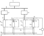
- the field level contains further, not shown here field devices that detect the states of a technical process in the form of sensors and designed as actuators affect the process targeted.
- the guide device 1 and the control computers 2, 3 are connected to each other via a system bus 5 (eg, Ethernet).
- the two control computers 2, 3 each operate in redundant operation from one and the same control or user program, wherein they inter alia via separate digital fieldbuses 6, 7 (eg PROFIBUS DP) process received input values from sensors.
- the connection of the field devices to the field buses 6, 7 of the two control computers 2, 3 is carried out by a first and a second decentralized peripheral station 8, 9.
- Each of the two peripheral stations 8, 9 consists of an interface module (head assembly) 10, 11 for connection to the respective field bus 6, 7 and a number of single or multi-channel peripheral modules, of which only one output module 12, 13 is shown here.
- the actuator 4 is connected via decoupling diodes 14, 15 to the signal outputs 16, 17 of the two output modules 12, 13.
- the interface modules 10, 11 transfer output values, which they receive from the respective control computer 2, 3 for the actuator 4, to the output module 12, 13, wherein the diodes 14, 15 for the actuator 4 disjunctively (OR) link digital values and analog values Add (streams). Both output modules 12, 13 are active. You will both receive the same output values in error-free redundancy mode.
- the two control computers 2, 3 equalize themselves accordingly.
- the interface modules 10, 11 each monitor the fieldbus 6, 7, to which they are connected, and in the event of a fault, z. B. in case of failure of the control computer (eg STOP mode, pulled cable, etc.) to all output modules of the relevant peripheral station 8, 9 an instruction to output replacement values, for example in the form of the last received output values.
- This behavior is necessary in non-redundant operation. In redundant operation, however, this leads to a faulty operating state.
- the output module 12, 13 supplying the actuator 4 redundantly with output values therefore only converts this command if and as long as both of them receive such an instruction. To enable this, they exchange information about receiving a replacement value command via a communication link (eg RS485). This prevents the actuator 4 z. B. instead of a current analog output value receives the sum of this and an output value frozen to the command.
Landscapes
- Physics & Mathematics (AREA)
- General Physics & Mathematics (AREA)
- Engineering & Computer Science (AREA)
- Automation & Control Theory (AREA)
- Safety Devices In Control Systems (AREA)
- Programmable Controllers (AREA)
Claims (6)
- Système de commande redondant- comprenant un actionneur (4),- comprenant un premier ordinateur (2) de commande, qui est relié par un premier bus (6 ) à un module (10) d'interface d'un premier poste (8) périphérique, comportant au moins un module périphérique et- comprenant un deuxième ordinateur (3) de commande redondant, qui est relié par un deuxième bus (7) à un module (11) d'interface d'un deuxième poste (9) périphérique, comportant également au moins un module périphérique, dans lequel- l'actionneur (4) est raccordé à des sorties (16, 17) de signal, découplées l'une de l'autre, de deux modules périphériques, formant chacun un module (12, 13) de sortie des deux postes (8, 9) périphériques et- chacun des modules (10, 11) d'interface est constitué pour transmettre, au module (12, 13) de sortie pour sortie vers l'actionneur (4), par l'intermédiaire des bus (6, 7), des valeurs de sortie obtenues de l'ordinateur (2, 3) de commande respectif,caractérisé en ce que- chacun des modules (10, 11) d'interface est constitué en outre pour, si une panne du côté du bus est détectée, transmettre aux modules (12, 13) de sortie et à tous les autres modules de sortie des postes (8, 9) périphériques, une instruction de sortir des valeurs de remplacement sur leurs sorties (16, 17) de signal.- les deux modules (12, 13) de sortie, aux sorties (16, 17) de signal desquelles est raccordé l'actionneur (4), sont reliés entre eux par une liaison (18) de communication et sont constitués pour échanger, pour la sortie d'une valeur de remplacement, des informations sur le contenu d'une instruction et pour ne suivre cette instruction que si l'autre module de sortie a reçu également une instruction de ce genre.
- Système de commande redondant suivant la revendication 1, caractérisé en ce que les deux modules (12, 13) de sortie sont des modules de sortie numériques.
- Système de commande redondant suivant la revendication 1, caractérisé en ce que les deux modules (12, 13) de sortie sont des modules de sortie analogiques.
- Système de commande redondant suivant l'une des revendications précédentes, caractérisé en ce que, dans une structure à plusieurs canaux des modules (12, 13) de sortie, ceux-ci sont constitués pour suivre une instruction reçue de sortir une valeur de remplacement seulement pour les canaux, aux sorties de signal desquelles l'actionneur (4) est raccordé, avec la limitation que l'autre module de sortie a reçu aussi une instruction de ce genre.
- Procédé de commande redondante d'un actionneur (4) dans un système de commande, dans lequel- un premier ordinateur (2) de commande est relié, par un premier bus (6), à un module (10) d'interface d'un premier poste (8) périphérique comportant au moins un module périphérique,- un deuxième ordinateur (3) de commande redondant est relié, par un deuxième bus (7) à un module (11) d'interface d'un deuxième poste (9) périphérique comportant également au moins un module périphérique et- l'actionneur (4) est raccordé à des sorties (16, 17) de signal, découplées l'une de l'autre, de deux modules périphériques, formant chacun un module (12, 13) de sortie des deux postes (8, 9) périphériques, dans lequel- chacun des modules (10, 11) d'interface transmet, par le bus (6, 7) de l'ordinateur (2, 3) de commande respectif, des valeurs de sortie reçues par l'actionneur (4) aux modules (12, 13) de sortie pour sortie vers l'actionneur (4),caractérisé en ce que- chacun des modules (10, 11) d'interface transmet, lorsqu'une panne du côté du bus est détectée, aux modules (12, 13) de sortie et à tous les autres modules de sortie du poste (8, 9) périphérique, une instruction de sortir des valeurs de remplacement sur leurs sorties (16, 17) de signal et- les deux modules (12, 13) de sortie, aux sorties (16, 17) de signal desquelles l'actionneur (4) est raccordé, échangent, par une liaison (18) de communication, des informations sur la réception d'une instruction de sortie d'une valeur de remplacement et ne suivent cette instruction que si l'autre module de sortie a reçu aussi une instruction de ce genre.
- Procédé suivant la revendication 5, caractérisé en ce que, pour une constitution à plusieurs canaux des modules (12, 13) de sortie, ceux-ci ne suivent une instruction reçue de sortir une valeur de remplacement que pour les canaux, aux sorties de signal desquelles l'actionneur (4) est raccordé, avec la limitation que l'autre module de sortie a reçu aussi une instruction de ce genre.
Priority Applications (3)
| Application Number | Priority Date | Filing Date | Title |
|---|---|---|---|
| EP16158266.3A EP3214512B1 (fr) | 2016-03-02 | 2016-03-02 | Systeme de commande redondant pour un actionneur et son procede de commande redondant |
| CN201710119597.5A CN107153351B (zh) | 2016-03-02 | 2017-03-01 | 作动器的冗余控制系统以及用于其冗余控制的方法 |
| US15/446,672 US10386832B2 (en) | 2016-03-02 | 2017-03-01 | Redundant control system for an actuator and method for redundant control thereof |
Applications Claiming Priority (1)
| Application Number | Priority Date | Filing Date | Title |
|---|---|---|---|
| EP16158266.3A EP3214512B1 (fr) | 2016-03-02 | 2016-03-02 | Systeme de commande redondant pour un actionneur et son procede de commande redondant |
Publications (2)
| Publication Number | Publication Date |
|---|---|
| EP3214512A1 EP3214512A1 (fr) | 2017-09-06 |
| EP3214512B1 true EP3214512B1 (fr) | 2018-04-25 |
Family
ID=55453085
Family Applications (1)
| Application Number | Title | Priority Date | Filing Date |
|---|---|---|---|
| EP16158266.3A Active EP3214512B1 (fr) | 2016-03-02 | 2016-03-02 | Systeme de commande redondant pour un actionneur et son procede de commande redondant |
Country Status (3)
| Country | Link |
|---|---|
| US (1) | US10386832B2 (fr) |
| EP (1) | EP3214512B1 (fr) |
| CN (1) | CN107153351B (fr) |
Families Citing this family (4)
| Publication number | Priority date | Publication date | Assignee | Title |
|---|---|---|---|---|
| DE102017109865A1 (de) * | 2017-05-08 | 2018-11-08 | Webasto SE | Verfahren zur Übermittlung mindestens eines Steuerbefehls und Steuereinrichtung |
| CN107738739B (zh) * | 2017-09-14 | 2019-04-09 | 北京精密机电控制设备研究所 | 一种离合器及基于离合器实现的并联冗余机电作动器 |
| CN107977289B (zh) * | 2017-11-07 | 2020-10-23 | 北京控制工程研究所 | 一种热备份计算机中多模冗余总线容错架构及其控制方法 |
| EP3936949A1 (fr) * | 2020-07-09 | 2022-01-12 | Siemens Aktiengesellschaft | Procédé de fonctionnement d'un système d'automatisation redondant et système d'automatisation redondant |
Family Cites Families (21)
| Publication number | Priority date | Publication date | Assignee | Title |
|---|---|---|---|---|
| US4872106A (en) * | 1983-04-06 | 1989-10-03 | New Forney Corp. | Industrial process control system with back-up data processors to take over from failed primary data processors |
| FR2600437B1 (fr) * | 1986-06-18 | 1993-12-31 | Telemecanique Electrique | Procede et dispositif pour la commande redondante d'un organe de puissance |
| US4958270A (en) * | 1989-01-23 | 1990-09-18 | Honeywell Inc. | Method for control data base updating of a redundant processor in a process control system |
| US5202822A (en) | 1990-09-26 | 1993-04-13 | Honeywell Inc. | Universal scheme of input/output redundancy in a process control system |
| CN1678914A (zh) * | 2002-07-04 | 2005-10-05 | 西门子公司 | 利用冗余传感器和分析电路确定旋转机器部件转数的装置 |
| DE10357797A1 (de) * | 2003-12-10 | 2005-08-04 | Siemens Ag | Peripherieeinheit für ein redundantes Steuersystem |
| DE10358989A1 (de) * | 2003-12-16 | 2005-08-04 | Siemens Ag | Redundantes Steuersystem |
| DE102004034451A1 (de) | 2004-07-16 | 2006-02-16 | Siemens Ag | Redundantes Steuersystem |
| US8260492B2 (en) * | 2005-08-05 | 2012-09-04 | Honeywell International Inc. | Method and system for redundancy management of distributed and recoverable digital control system |
| DE102009007215A1 (de) * | 2009-02-03 | 2010-08-05 | Siemens Aktiengesellschaft | Automatisierungssystem mit einem programmierbaren Matrixmodul |
| JP5590955B2 (ja) * | 2010-04-26 | 2014-09-17 | ナブテスコ株式会社 | アクチュエータ制御システム |
| DE102012003242A1 (de) * | 2012-02-20 | 2013-08-22 | Phoenix Contact Gmbh & Co. Kg | Verfahren zum ausfallsicheren Betreiben eines Prozesssteuersystems mit redundanten Steuereinrichtungen |
| US9631645B2 (en) * | 2013-02-27 | 2017-04-25 | Woodward, Inc. | Rotary piston actuator anti-rotation configurations |
| US9593696B2 (en) * | 2013-02-27 | 2017-03-14 | Woodward, Inc. | Rotary piston type actuator with hydraulic supply |
| EP2972601B1 (fr) * | 2013-03-14 | 2019-07-03 | TTTech Auto AG | Procédé de limitation des risques d'erreurs dans un systeme de commande relatif à la sécurité redondant pour un véhicule à moteur |
| EP2799947B1 (fr) | 2013-05-03 | 2016-03-23 | Siemens Aktiengesellschaft | Agencement doté d'un premier et d'un deuxième appareils périphériques |
| EP2806316B1 (fr) * | 2013-05-24 | 2017-07-05 | Siemens Aktiengesellschaft | Procédé destiné au fonctionnement d'un système d'automatisation |
| EP2860598B1 (fr) * | 2013-10-14 | 2018-03-21 | Siemens Aktiengesellschaft | Procédé d'operation d' un système d'automatisation redondant, dans lequel l' esclave exécute de fonctions diagnostiques |
| US10042330B2 (en) * | 2014-05-07 | 2018-08-07 | Honeywell International Inc. | Redundant process controllers for segregated supervisory and industrial control networks |
| FR3024925B1 (fr) * | 2014-08-14 | 2016-08-26 | Zodiac Aero Electric | Systeme et procede de commande d'au moins un organe de puissance, notamment pour aeronef |
| US9990286B1 (en) * | 2017-05-05 | 2018-06-05 | Honeywell International, Inc. | Memory tracking using copy-back cache for 1:1 device redundancy |
-
2016
- 2016-03-02 EP EP16158266.3A patent/EP3214512B1/fr active Active
-
2017
- 2017-03-01 US US15/446,672 patent/US10386832B2/en active Active
- 2017-03-01 CN CN201710119597.5A patent/CN107153351B/zh active Active
Non-Patent Citations (1)
| Title |
|---|
| None * |
Also Published As
| Publication number | Publication date |
|---|---|
| CN107153351B (zh) | 2020-10-09 |
| US20170255191A1 (en) | 2017-09-07 |
| US10386832B2 (en) | 2019-08-20 |
| CN107153351A (zh) | 2017-09-12 |
| EP3214512A1 (fr) | 2017-09-06 |
Similar Documents
| Publication | Publication Date | Title |
|---|---|---|
| DE102006047026B4 (de) | Verfahren und System zum redundanten Ansteuern einer Slaveeinrichtung | |
| EP2981868B1 (fr) | Système de commande et de transmission de données, dispositif de traitement et procédé de commande de processus redondante à redondance décentralisée | |
| EP2504740B1 (fr) | Module de sécurité pour un appareil d'automatisation | |
| EP3170287B1 (fr) | Système de commande et de transmission de données, module de passerelle, module e/a et procédé de commande de processus | |
| EP1927914B1 (fr) | Module de sécurité et système d'automatisation | |
| EP2817682B1 (fr) | Procédé permettant un fonctionnement à sécurité intégrée d'un système de commande de processus à l'aide de dispositifs de commande redondants | |
| EP3214512B1 (fr) | Systeme de commande redondant pour un actionneur et son procede de commande redondant | |
| DE102016000126B4 (de) | Serielles Bussystem mit Koppelmodulen | |
| EP1860564A1 (fr) | Procédé et dispositif destinés à l'échange de données sur la base du protocole de communication OPC entre des composants redondants d'un système d'automatisation | |
| EP2857913B1 (fr) | Système d'automatisation redondant | |
| EP2667269B1 (fr) | Procédé de fonctionnement d'un système d'automatisation redondant | |
| DE4416795C2 (de) | Redundant konfigurierbares Übertragungssystem zum Datenaustausch und Verfahren zu dessen Betrieb | |
| DE19744071B4 (de) | Eine programmierbare Logiksteuervorrichtung verwendendes Steuerungssystem | |
| WO2005106603A1 (fr) | Systeme d'automatisation redondant comprenant un automate programmable maitre et un automate programmable reserve | |
| EP0782722B1 (fr) | Procede et dispositif permettant de commander et d'activer des detecteurs et/ou des organes d'actionnement relies par un systeme de bus | |
| EP1672446B1 (fr) | Module d'entrée/sortie sécurisé pour un controleur | |
| EP1619565B1 (fr) | Procédure et dispositif pour commuter sûrement un système d'automatisation avec bus. | |
| EP3336624B1 (fr) | Système comprenant deux modules redondants se surveillant mutuellement | |
| EP2418580B1 (fr) | Procédé destiné au fonctionnement d'un réseau et réseau | |
| DE102011051629B3 (de) | Sicherheitsbussystem | |
| DE102009005399B4 (de) | Verfahren und Kommunikationssystem zum Konfigurieren eines einen Logikbaustein enthaltenden Kommunikationsmoduls | |
| EP2942686B1 (fr) | Système de commande et de transmission de données pour la transmission de données liées à la sécurité par l'intermédiaire d'un support de communication | |
| EP2806316B1 (fr) | Procédé destiné au fonctionnement d'un système d'automatisation | |
| EP1692578A1 (fr) | Unite peripherique d'un systeme de commande redondant | |
| EP2980661A1 (fr) | Appareil de commande électronique |
Legal Events
| Date | Code | Title | Description |
|---|---|---|---|
| PUAI | Public reference made under article 153(3) epc to a published international application that has entered the european phase |
Free format text: ORIGINAL CODE: 0009012 |
|
| STAA | Information on the status of an ep patent application or granted ep patent |
Free format text: STATUS: REQUEST FOR EXAMINATION WAS MADE |
|
| 17P | Request for examination filed |
Effective date: 20161206 |
|
| AK | Designated contracting states |
Kind code of ref document: A1 Designated state(s): AL AT BE BG CH CY CZ DE DK EE ES FI FR GB GR HR HU IE IS IT LI LT LU LV MC MK MT NL NO PL PT RO RS SE SI SK SM TR |
|
| AX | Request for extension of the european patent |
Extension state: BA ME |
|
| REG | Reference to a national code |
Ref country code: DE Ref legal event code: R079 Ref document number: 502016000932 Country of ref document: DE Free format text: PREVIOUS MAIN CLASS: G05B0019050000 Ipc: G05B0023020000 |
|
| GRAP | Despatch of communication of intention to grant a patent |
Free format text: ORIGINAL CODE: EPIDOSNIGR1 |
|
| STAA | Information on the status of an ep patent application or granted ep patent |
Free format text: STATUS: GRANT OF PATENT IS INTENDED |
|
| RIC1 | Information provided on ipc code assigned before grant |
Ipc: G05B 23/02 20060101AFI20170919BHEP Ipc: G05B 19/05 20060101ALI20170919BHEP Ipc: G05B 9/03 20060101ALI20170919BHEP |
|
| INTG | Intention to grant announced |
Effective date: 20171004 |
|
| GRAS | Grant fee paid |
Free format text: ORIGINAL CODE: EPIDOSNIGR3 |
|
| GRAF | Information related to payment of grant fee modified |
Free format text: ORIGINAL CODE: EPIDOSCIGR3 |
|
| GRAA | (expected) grant |
Free format text: ORIGINAL CODE: 0009210 |
|
| STAA | Information on the status of an ep patent application or granted ep patent |
Free format text: STATUS: THE PATENT HAS BEEN GRANTED |
|
| AK | Designated contracting states |
Kind code of ref document: B1 Designated state(s): AL AT BE BG CH CY CZ DE DK EE ES FI FR GB GR HR HU IE IS IT LI LT LU LV MC MK MT NL NO PL PT RO RS SE SI SK SM TR |
|
| REG | Reference to a national code |
Ref country code: GB Ref legal event code: FG4D Free format text: NOT ENGLISH |
|
| REG | Reference to a national code |
Ref country code: CH Ref legal event code: EP |
|
| REG | Reference to a national code |
Ref country code: AT Ref legal event code: REF Ref document number: 993557 Country of ref document: AT Kind code of ref document: T Effective date: 20180515 |
|
| REG | Reference to a national code |
Ref country code: IE Ref legal event code: FG4D Free format text: LANGUAGE OF EP DOCUMENT: GERMAN |
|
| REG | Reference to a national code |
Ref country code: DE Ref legal event code: R096 Ref document number: 502016000932 Country of ref document: DE |
|
| REG | Reference to a national code |
Ref country code: NL Ref legal event code: MP Effective date: 20180425 |
|
| REG | Reference to a national code |
Ref country code: LT Ref legal event code: MG4D |
|
| PG25 | Lapsed in a contracting state [announced via postgrant information from national office to epo] |
Ref country code: NL Free format text: LAPSE BECAUSE OF FAILURE TO SUBMIT A TRANSLATION OF THE DESCRIPTION OR TO PAY THE FEE WITHIN THE PRESCRIBED TIME-LIMIT Effective date: 20180425 |
|
| PG25 | Lapsed in a contracting state [announced via postgrant information from national office to epo] |
Ref country code: BG Free format text: LAPSE BECAUSE OF FAILURE TO SUBMIT A TRANSLATION OF THE DESCRIPTION OR TO PAY THE FEE WITHIN THE PRESCRIBED TIME-LIMIT Effective date: 20180725 Ref country code: FI Free format text: LAPSE BECAUSE OF FAILURE TO SUBMIT A TRANSLATION OF THE DESCRIPTION OR TO PAY THE FEE WITHIN THE PRESCRIBED TIME-LIMIT Effective date: 20180425 Ref country code: NO Free format text: LAPSE BECAUSE OF FAILURE TO SUBMIT A TRANSLATION OF THE DESCRIPTION OR TO PAY THE FEE WITHIN THE PRESCRIBED TIME-LIMIT Effective date: 20180725 Ref country code: SE Free format text: LAPSE BECAUSE OF FAILURE TO SUBMIT A TRANSLATION OF THE DESCRIPTION OR TO PAY THE FEE WITHIN THE PRESCRIBED TIME-LIMIT Effective date: 20180425 Ref country code: PL Free format text: LAPSE BECAUSE OF FAILURE TO SUBMIT A TRANSLATION OF THE DESCRIPTION OR TO PAY THE FEE WITHIN THE PRESCRIBED TIME-LIMIT Effective date: 20180425 Ref country code: LT Free format text: LAPSE BECAUSE OF FAILURE TO SUBMIT A TRANSLATION OF THE DESCRIPTION OR TO PAY THE FEE WITHIN THE PRESCRIBED TIME-LIMIT Effective date: 20180425 Ref country code: ES Free format text: LAPSE BECAUSE OF FAILURE TO SUBMIT A TRANSLATION OF THE DESCRIPTION OR TO PAY THE FEE WITHIN THE PRESCRIBED TIME-LIMIT Effective date: 20180425 |
|
| PG25 | Lapsed in a contracting state [announced via postgrant information from national office to epo] |
Ref country code: HR Free format text: LAPSE BECAUSE OF FAILURE TO SUBMIT A TRANSLATION OF THE DESCRIPTION OR TO PAY THE FEE WITHIN THE PRESCRIBED TIME-LIMIT Effective date: 20180425 Ref country code: RS Free format text: LAPSE BECAUSE OF FAILURE TO SUBMIT A TRANSLATION OF THE DESCRIPTION OR TO PAY THE FEE WITHIN THE PRESCRIBED TIME-LIMIT Effective date: 20180425 Ref country code: GR Free format text: LAPSE BECAUSE OF FAILURE TO SUBMIT A TRANSLATION OF THE DESCRIPTION OR TO PAY THE FEE WITHIN THE PRESCRIBED TIME-LIMIT Effective date: 20180726 Ref country code: LV Free format text: LAPSE BECAUSE OF FAILURE TO SUBMIT A TRANSLATION OF THE DESCRIPTION OR TO PAY THE FEE WITHIN THE PRESCRIBED TIME-LIMIT Effective date: 20180425 |
|
| PG25 | Lapsed in a contracting state [announced via postgrant information from national office to epo] |
Ref country code: PT Free format text: LAPSE BECAUSE OF FAILURE TO SUBMIT A TRANSLATION OF THE DESCRIPTION OR TO PAY THE FEE WITHIN THE PRESCRIBED TIME-LIMIT Effective date: 20180827 |
|
| REG | Reference to a national code |
Ref country code: DE Ref legal event code: R097 Ref document number: 502016000932 Country of ref document: DE |
|
| PG25 | Lapsed in a contracting state [announced via postgrant information from national office to epo] |
Ref country code: RO Free format text: LAPSE BECAUSE OF FAILURE TO SUBMIT A TRANSLATION OF THE DESCRIPTION OR TO PAY THE FEE WITHIN THE PRESCRIBED TIME-LIMIT Effective date: 20180425 Ref country code: SK Free format text: LAPSE BECAUSE OF FAILURE TO SUBMIT A TRANSLATION OF THE DESCRIPTION OR TO PAY THE FEE WITHIN THE PRESCRIBED TIME-LIMIT Effective date: 20180425 Ref country code: EE Free format text: LAPSE BECAUSE OF FAILURE TO SUBMIT A TRANSLATION OF THE DESCRIPTION OR TO PAY THE FEE WITHIN THE PRESCRIBED TIME-LIMIT Effective date: 20180425 Ref country code: DK Free format text: LAPSE BECAUSE OF FAILURE TO SUBMIT A TRANSLATION OF THE DESCRIPTION OR TO PAY THE FEE WITHIN THE PRESCRIBED TIME-LIMIT Effective date: 20180425 Ref country code: CZ Free format text: LAPSE BECAUSE OF FAILURE TO SUBMIT A TRANSLATION OF THE DESCRIPTION OR TO PAY THE FEE WITHIN THE PRESCRIBED TIME-LIMIT Effective date: 20180425 |
|
| PG25 | Lapsed in a contracting state [announced via postgrant information from national office to epo] |
Ref country code: SM Free format text: LAPSE BECAUSE OF FAILURE TO SUBMIT A TRANSLATION OF THE DESCRIPTION OR TO PAY THE FEE WITHIN THE PRESCRIBED TIME-LIMIT Effective date: 20180425 |
|
| PLBE | No opposition filed within time limit |
Free format text: ORIGINAL CODE: 0009261 |
|
| STAA | Information on the status of an ep patent application or granted ep patent |
Free format text: STATUS: NO OPPOSITION FILED WITHIN TIME LIMIT |
|
| 26N | No opposition filed |
Effective date: 20190128 |
|
| PG25 | Lapsed in a contracting state [announced via postgrant information from national office to epo] |
Ref country code: MC Free format text: LAPSE BECAUSE OF FAILURE TO SUBMIT A TRANSLATION OF THE DESCRIPTION OR TO PAY THE FEE WITHIN THE PRESCRIBED TIME-LIMIT Effective date: 20180425 |
|
| REG | Reference to a national code |
Ref country code: CH Ref legal event code: PL |
|
| PG25 | Lapsed in a contracting state [announced via postgrant information from national office to epo] |
Ref country code: AL Free format text: LAPSE BECAUSE OF FAILURE TO SUBMIT A TRANSLATION OF THE DESCRIPTION OR TO PAY THE FEE WITHIN THE PRESCRIBED TIME-LIMIT Effective date: 20180425 Ref country code: LU Free format text: LAPSE BECAUSE OF NON-PAYMENT OF DUE FEES Effective date: 20190302 |
|
| REG | Reference to a national code |
Ref country code: BE Ref legal event code: MM Effective date: 20190331 |
|
| PG25 | Lapsed in a contracting state [announced via postgrant information from national office to epo] |
Ref country code: IE Free format text: LAPSE BECAUSE OF NON-PAYMENT OF DUE FEES Effective date: 20190302 Ref country code: CH Free format text: LAPSE BECAUSE OF NON-PAYMENT OF DUE FEES Effective date: 20190331 Ref country code: LI Free format text: LAPSE BECAUSE OF NON-PAYMENT OF DUE FEES Effective date: 20190331 |
|
| PG25 | Lapsed in a contracting state [announced via postgrant information from national office to epo] |
Ref country code: BE Free format text: LAPSE BECAUSE OF NON-PAYMENT OF DUE FEES Effective date: 20190331 |
|
| PG25 | Lapsed in a contracting state [announced via postgrant information from national office to epo] |
Ref country code: TR Free format text: LAPSE BECAUSE OF FAILURE TO SUBMIT A TRANSLATION OF THE DESCRIPTION OR TO PAY THE FEE WITHIN THE PRESCRIBED TIME-LIMIT Effective date: 20180425 |
|
| PG25 | Lapsed in a contracting state [announced via postgrant information from national office to epo] |
Ref country code: MT Free format text: LAPSE BECAUSE OF FAILURE TO SUBMIT A TRANSLATION OF THE DESCRIPTION OR TO PAY THE FEE WITHIN THE PRESCRIBED TIME-LIMIT Effective date: 20180425 |
|
| PG25 | Lapsed in a contracting state [announced via postgrant information from national office to epo] |
Ref country code: CY Free format text: LAPSE BECAUSE OF FAILURE TO SUBMIT A TRANSLATION OF THE DESCRIPTION OR TO PAY THE FEE WITHIN THE PRESCRIBED TIME-LIMIT Effective date: 20180425 |
|
| PG25 | Lapsed in a contracting state [announced via postgrant information from national office to epo] |
Ref country code: IS Free format text: LAPSE BECAUSE OF FAILURE TO SUBMIT A TRANSLATION OF THE DESCRIPTION OR TO PAY THE FEE WITHIN THE PRESCRIBED TIME-LIMIT Effective date: 20180825 |
|
| PG25 | Lapsed in a contracting state [announced via postgrant information from national office to epo] |
Ref country code: HU Free format text: LAPSE BECAUSE OF FAILURE TO SUBMIT A TRANSLATION OF THE DESCRIPTION OR TO PAY THE FEE WITHIN THE PRESCRIBED TIME-LIMIT; INVALID AB INITIO Effective date: 20160302 |
|
| PG25 | Lapsed in a contracting state [announced via postgrant information from national office to epo] |
Ref country code: SI Free format text: LAPSE BECAUSE OF FAILURE TO SUBMIT A TRANSLATION OF THE DESCRIPTION OR TO PAY THE FEE WITHIN THE PRESCRIBED TIME-LIMIT Effective date: 20180425 |
|
| REG | Reference to a national code |
Ref country code: AT Ref legal event code: MM01 Ref document number: 993557 Country of ref document: AT Kind code of ref document: T Effective date: 20210302 |
|
| PG25 | Lapsed in a contracting state [announced via postgrant information from national office to epo] |
Ref country code: MK Free format text: LAPSE BECAUSE OF FAILURE TO SUBMIT A TRANSLATION OF THE DESCRIPTION OR TO PAY THE FEE WITHIN THE PRESCRIBED TIME-LIMIT Effective date: 20180425 |
|
| PG25 | Lapsed in a contracting state [announced via postgrant information from national office to epo] |
Ref country code: AT Free format text: LAPSE BECAUSE OF NON-PAYMENT OF DUE FEES Effective date: 20210302 |
|
| PGFP | Annual fee paid to national office [announced via postgrant information from national office to epo] |
Ref country code: IT Payment date: 20240321 Year of fee payment: 9 Ref country code: FR Payment date: 20240319 Year of fee payment: 9 |
|
| PGFP | Annual fee paid to national office [announced via postgrant information from national office to epo] |
Ref country code: GB Payment date: 20240409 Year of fee payment: 9 |
|
| PGFP | Annual fee paid to national office [announced via postgrant information from national office to epo] |
Ref country code: DE Payment date: 20240517 Year of fee payment: 9 |