EP0791874B1 - Verfahren und Vorrichtung zum Steuern von binären Sensoren und/oder Aktuatoren - Google Patents
Verfahren und Vorrichtung zum Steuern von binären Sensoren und/oder Aktuatoren Download PDFInfo
- Publication number
- EP0791874B1 EP0791874B1 EP97201131A EP97201131A EP0791874B1 EP 0791874 B1 EP0791874 B1 EP 0791874B1 EP 97201131 A EP97201131 A EP 97201131A EP 97201131 A EP97201131 A EP 97201131A EP 0791874 B1 EP0791874 B1 EP 0791874B1
- Authority
- EP
- European Patent Office
- Prior art keywords
- asi
- master
- data
- processing computer
- flags
- Prior art date
- Legal status (The legal status is an assumption and is not a legal conclusion. Google has not performed a legal analysis and makes no representation as to the accuracy of the status listed.)
- Expired - Lifetime
Links
Images


Classifications
-
- G—PHYSICS
- G05—CONTROLLING; REGULATING
- G05B—CONTROL OR REGULATING SYSTEMS IN GENERAL; FUNCTIONAL ELEMENTS OF SUCH SYSTEMS; MONITORING OR TESTING ARRANGEMENTS FOR SUCH SYSTEMS OR ELEMENTS
- G05B19/00—Programme-control systems
- G05B19/02—Programme-control systems electric
- G05B19/418—Total factory control, i.e. centrally controlling a plurality of machines, e.g. direct or distributed numerical control [DNC], flexible manufacturing systems [FMS], integrated manufacturing systems [IMS], computer integrated manufacturing [CIM]
- G05B19/4185—Total factory control, i.e. centrally controlling a plurality of machines, e.g. direct or distributed numerical control [DNC], flexible manufacturing systems [FMS], integrated manufacturing systems [IMS], computer integrated manufacturing [CIM] characterised by the network communication
-
- G—PHYSICS
- G05—CONTROLLING; REGULATING
- G05B—CONTROL OR REGULATING SYSTEMS IN GENERAL; FUNCTIONAL ELEMENTS OF SUCH SYSTEMS; MONITORING OR TESTING ARRANGEMENTS FOR SUCH SYSTEMS OR ELEMENTS
- G05B2219/00—Program-control systems
- G05B2219/30—Nc systems
- G05B2219/31—From computer integrated manufacturing till monitoring
- G05B2219/31154—Actuator sensor bus, asi, intelligent actuator, motor, sensor
-
- G—PHYSICS
- G05—CONTROLLING; REGULATING
- G05B—CONTROL OR REGULATING SYSTEMS IN GENERAL; FUNCTIONAL ELEMENTS OF SUCH SYSTEMS; MONITORING OR TESTING ARRANGEMENTS FOR SUCH SYSTEMS OR ELEMENTS
- G05B2219/00—Program-control systems
- G05B2219/30—Nc systems
- G05B2219/31—From computer integrated manufacturing till monitoring
- G05B2219/31209—Master actuator sensor interface has priority over host, build into host
-
- Y—GENERAL TAGGING OF NEW TECHNOLOGICAL DEVELOPMENTS; GENERAL TAGGING OF CROSS-SECTIONAL TECHNOLOGIES SPANNING OVER SEVERAL SECTIONS OF THE IPC; TECHNICAL SUBJECTS COVERED BY FORMER USPC CROSS-REFERENCE ART COLLECTIONS [XRACs] AND DIGESTS
- Y02—TECHNOLOGIES OR APPLICATIONS FOR MITIGATION OR ADAPTATION AGAINST CLIMATE CHANGE
- Y02P—CLIMATE CHANGE MITIGATION TECHNOLOGIES IN THE PRODUCTION OR PROCESSING OF GOODS
- Y02P90/00—Enabling technologies with a potential contribution to greenhouse gas [GHG] emissions mitigation
- Y02P90/02—Total factory control, e.g. smart factories, flexible manufacturing systems [FMS] or integrated manufacturing systems [IMS]
Definitions
- the invention relates to a method for controlling and activating one another binary sensors and / or actuators networked by means of a bus system (ASI slaves), with the bus system being operated by an ASI master and the processing of the ASI data is carried out by a processing computer is and ASI master and processing computer ASI data and ASI flags exchange with each other according to the preamble of claim 1 and a device according to the preamble of patent claim 7.
- ASI slaves bus system
- ASI standard created the one Fieldbus concept with which binary actuators and sensors with the lowest or first control level can be linked to make them communicative close.
- the actuator sensor interface replaces the Wiring harness, distribution cabinets, terminal strips etc. using a simple two-wire ribbon cable, via the ASI data with the peripheral elements be exchanged and that they are also supplied with energy.
- ASI With a so-called separate ASI connection in the form of a standardized module, is part of the bus structure, ASI does most of it first conventional peripheral elements can be connected via bus. With the integrated ASI connection however, if there is a so-called slave module in a device, which is itself bus-compatible (ASI association in: special print from fieldbus systems for the capital goods industry, publisher VDMA, Frankfurt 1992, 3.12.1992 as well as publication: VariNet-A factory automation Actuator sensor interface Catalog Sensor Systems 5, Edition 1994, publisher: Pepperl + Fuchs GmbH, 68301 Mannheim; as well as publication: ASI: Das Actuator sensor interface for automation, published by Werner Kriesel and Otto Madelung, Hanser Verlag 1994).
- the master takes on all the tasks that are necessary for the settlement bus operation of the slaves are necessary including tasks initialization and diagnosis.
- ASI master Via the ASI master is to the Fieldbus a higher-level processing computer, such as programmable logic controllers Controller or bus computer or PC or VME bus computer, connected, to which all signals of all ASI slaves are fed, the ASI master ensures that the signals the processing computer in a fixed Time frames are made available and vice versa the control commands of the processing computer to the ASI slaves.
- the ASI-Master also ensures that new slaves are recognized and failed slaves are reported to the processing computer; the ASI master thus fits the ASI functions of the slaves to the external processing system of the processing computer.
- the ASI master owns for Processing these tasks typically involves a controller working a tight Must adhere to the time grid.
- the bit time at ASI is 6 ⁇ sec (microseconds), the controller cyclically sending a complete ASI telegram every 150 ⁇ sec must evaluate. At any time, a situation can arise with the ASI master must put the ASI circuit in a safe state.
- the invention has for its object a method and an apparatus of the type mentioned at the beginning, with which the ASI data in general and the ASI flags between the processing computer and the ASI master can be transferred without data inconsistency.
- the object of the method according to the invention is that to ensure the consistency between ASI data and ASI flags of the ASI master the ASI data and the ASI flags before transmission to the processing computer freezes, so no longer changes, and the ASI master the thereby consistent ASI data and the ASI flags at the same Time or at different times together in a function or in transfers various functions to the processing computer.
- the ASI master thus transmits the ASI data first and then the ASI flags, ensuring that the ASI flags are in progress the transfer function is not set to "ok” but only to "false" can be.
- the ASI master saves the ASI data and the ASI flags at the same time or at different times internally between and changes during the Transmission of the ASI data and the ASI flags to the processing computer the same no longer.
- the ASI master advantageously checks the ASI flags in one function and adds error-free state on "ok", whereby this function is not asynchronous to the transmission processed the ASI data and ASI flags to the processing computer becomes.
- an additional error bit can be generated which are only set by the ASI master and only by the Processing computer can be deleted or acknowledged, and errors saved by storing errors by the host computer software a consistency of the ASI data when exchanging data between the processing computer and the ASI master is reached.
- a device of the type mentioned is characterized in that for Ensuring the consistency between the ASI data and the ASI flags Device the ASI data and the ASI flags before transmission to the processing computer is able to freeze, so no longer changed, and and the ASI master, the mutually consistent ASI data and the ASI flags at the same time or at different times together in one Function or in various functions to the processing computer transmits.
- ASI master detects an error at any time, then the corresponding ASI flags can be described in accordance with the specification become.
- ASI flags for example, a global one ASI error bit is set, which is only set by the ASI master and only by the processing computer software may be deleted.
- One from the ASI master Detected errors are saved for the processing computer. By the Saving errors becomes a consistency of the ASI data when exchanging data reached between the processing computer and the ASI master.
- the processing computer can respond to short-term ASI errors in a Processing computer software respond to the specified manner.
- the ASI master implemented in the ASI control master has the implemented processing computer always and at any time higher priority.
- the timing of the ASI master must not at any time and under no circumstances by the implemented processing computer changed, slowed down or interrupted.
- the ASI master or the ASI master software can use the implemented processing computer interrupt at any time; the ASI master or the ASI master software is thus able to measure the cycle time of the processing computer software to change that can be changeable. Reactions of the internal ASI masters for errors are in a time grid, preferably a fixed time grid, carried out.
- the ASI specification which specifies the requirements for an ASI master state-of-the-art are described, writes process and response times strictly for different states in the ASI system.
- the Computing time requirements for the different states are very different, only very much Few ASI system states are difficult to process in the ASI master.
- Very Processing error states in the ASI system for example, is time-consuming or the automatic inclusion of additionally connected ASI slaves in correct operation.
- the ASI system states which are difficult to edit cannot be simplified according to the current state of the art, without significant restrictions in operational safety and comfort of the ASI system.
- the ASI system states which are difficult to edit, come in real Operation of an ASI system is very rare. However, they are crucial for the minimum power requirement in an ASI master.
- the data exchange between the ASI master and the processing computer takes place in a way that data consistency is ensured, what for when exchanging between ASI master and processing computer to ensure the Consistency between ASI data and ASI flags of the ASI master the ASI data and freezes the ASI flags before transmission to the host, So no longer changed, for example cached, and this to each other consistent ASI data and ASI flags to the processing computer transmits.
- This can be done if the ASI master detects an error additional error bits are set that are only set by the ASI master and may only be deleted or acknowledged by the processing computer, and Errors are saved, by saving errors by the Processing computer software a consistency of the ASI data during data exchange between the processing computer and the ASI master.
- ASI slaves to control and activate each other using a Bus systems networked binary sensors and / or actuators (ASI slaves), the operation of the bus system by an ASI master and the Processing of the ASI data carried out by a processing computer and the ASI master and the processing computer ASI data and ASI flags exchange with each other and when exchanging the consistency between ASI data and ASI flags are ensured, proceed according to the invention in this way that the ASI master the ASI data and the ASI flags before transmission freezes to the processing computer, i.e. no longer changes, or for example cached, and this mutually consistent ASI data and transmits ASI flags to the processing computer.
- the ASI master preferably transmits ASI data first and then the ASI flags, whereby the ASI master can ensure that the ASI flags while processing the transfer function not on "ok” but only can be set to "false”. This ensures that the processing computer no errors overlooked.
- the ASI master saves the ASI data and the ASI flags at the same time or immediately one after the other between, whereby during the Transfer to the processing computer no changes in the ASI data and the ASI flags no longer take place.
- the ASI master can use the ASI data and the ASI flags together in one function or in different functions transferred to the processing computer.
- the ASI master can use the ASI flags check in a function and set it to "ok" if it is free of errors, this function is not asynchronous to the transmission of the ASI data and ASI flags may be edited or processed on the processing computer.
- an additional Error bit is set, which is only set by the ASI master and only by the Processing computer may be deleted or acknowledged, and errors saved by storing errors by the host computer software a consistency of the ASI data when exchanging data between the processing computer (s) and the ASI master is reached.
- a function is used in the ASI master to read the input data from the ASI master and to transmit it to a processing computer, and a second function to transmit the ASI flags to a processing computer as follows:
- Status Read input data image () [function] argument Argument value description --- --- --- result Result value description image
- ASI data Contains the states at the inputs of the active slaves and default data for inactive slaves status Displays the result of the function OK
- the ASI data could be read NOK
- the ASI data could not be read
- Default data for inactive slaves are in the input data image.
- the default data can no longer of real input states in the processing computer be distinguished.
- the ASI data could be read NOK
- the ASI data could not be read ASI flags Contains the ASI flags of the process control level
- the ASI flags contain information about the operating state of the bus system. Error states such as a voltage drop or the absence of ASI slaves is reported from the master to the processing computer via the ASI flags. There is therefore a time lag between access to the input data and access to the ASI flags. Within this time offset the operating status of the system can change.
- the ASI data and the ASI flags are in the ASI master simultaneously or immediately in succession without interruption by another function updated.
- the processing computer would have faulty process or default data work without recognizing the error in the ASI system.
- FIG. 1 shows the implementation of an ASI master 1 and a processing computer 2 within a device 3, the so-called ASI control master 3, which is connected via a line 4 to the ASI cable 5, on which a plurality of ASI slaves 6 are connected.
- FIG. 2 shows the principle of operation of the ASI control master by means of the implemented ASI masters and the implemented processing computer shown.
- the ASI master processes its ASI master software 11, the processing computer edits its host computer software 12; both asynchronous Processes can be independent of each other, as shown, whereby A data exchange takes place between the two software parts, which is due to the Loop "data exchange" connecting both processes is shown.
- the processing computer software works error-free, even if for any Time changes in the ASI circle occur.
- the timing of the ASI master and the processing computer runs asynchronously.
- the two Processes ASI master and processing computer can be decoupled completely independently work and then come into contact only for data exchange. Between the data exchange phases, the ASI master and the Processing computer decoupled and work autonomously.
- FIG. 3 shows the cyclical chronological sequence of the processing computer software of the processing computer shown in the event that the ASI control master on a controller is implemented.
- 3 shows the cyclical, chronological sequence the processing computer software, taking into account the different large time slices available to the processing computer from the ASI master be presented.
- the cycle time of the processing computer, So the time between the start of two data exchange phases depends a large part of the computing time provided.
- the ASI control master will only process the processing computer for as long Computing time made available, as the ASI master does not take up any computing time, So in the gaps in the cycle time of the ASI telegram, this Gaps can vary in size.
- the different lengths of these time slices, which are made available to the processing computer depend on the ASI master,
- Figure 5 shows a possible main diagram for data exchange starting with the start of data exchange. After the start of data exchange it is queried whether an ASI error has occurred; if affirmative the ASI circuit has entered the safe state. If the answer is no, the Data exchange carried out. Then it is queried again whether an ASI error if affirmative the ASI error has occurred in the past queried and if the answer is affirmative, loop back to the first question gone after the first ASI error. If the answer is no, the end of the Data exchange displayed and completed.
- the ASI circuit becomes advantageous if the processing computer software is incorrectly programmed continue to operate according to specifications, so that error programming the process of the ASI master software of the ASI master is not influenced, whereby the ASI master the ASI circuit regardless of the state of the Able to put processing computer software in a safe state is. Furthermore, the processing computer is in for short-term ASI errors a predetermined way in the processing computer software able to respond.
- the cyclic call of the ASI master software can be done with Be monitored with the help of a watchdog. For example, the ASI master reported via the watchdog that the control program is in an endless loop then the ASI master can switch the ASI circuit into a safe one Move state.
- a safe and safe condition at ASI is, for example the offline phase. In the offline phase, first all ASI slaves a RESET is carried out and then the communication on the ASI line set. After the RESET and the setting of the communication there is no further danger for an installation.
- an ASI power fail such as power failure on the bus
- the ASI control master immediately switched to the offline phase, independently on the state of the processing computer software. If an ASI slave fails, then the ASI master deletes the slave from the list of detected slaves and the data and parameter values of the slave in the ASI master software are described with default values, for example, which is independent of the Condition of the processing computer software happens.
- the ASI master or the ASI master software may cycle the processing computer software to change. Only the ASI master swaps over its own Interface to the outside of the ASI control master ASI data with the ASI slaves from, the processing computer the ASI data of the processing computer exchanges with the ASI master, which in turn for the entire data exchange with the ASI slaves; data exchange with the ASI slaves is operated by the ASI master.
- the processing computer transfers the ASI data the processing computer software to the ASI master, which is used for forwarding the ASI data and data exchange with the ASI slaves.
- the object of the invention is in particular for control methods and activation of binary networked with each other by means of a bus system Sensors and / or actuators, ASI slaves, applicable by a processing computer can be controlled and vice versa.
- the usefulness of Invention lies in the consistency between ASI data and ASI flags is guaranteed and that ASI master consistently with ASI data and ASI flags can exchange a processing computer.
Description
| Status = Eingangsdatenabbild_lesen() [Funktion] | ||
| Argument | Argumentwert | Beschreibung |
| --- | --- | --- |
| Resultat | Resultatwert | Beschreibung |
| Abbild | ASI-Daten | Enthält die Zustände an den Eingängen der aktiven Slaves und Default-Daten bei inaktiven Slaves |
| Status | Zeigt das Ergebnis der Funktion an | |
| OK | Die ASI-Daten konnten gelesen werden | |
| NOK | Die ASI-Daten konnten nicht gelesen werden |
| Status = ASI-Flags_lesen() [Funktion] | ||
| Argument | Argumentwert | Beschreibung |
| --- | --- | --- |
| Resultat | Resultatwert | Beschreibung |
| Status | Zeigt das Ergebnis der Funktion an | |
| OK | Die ASI-Daten konnten gelesen werden | |
| NOK | Die ASI-Daten konnten nicht gelesen werden | |
| ASI-Flags | Enthält die ASI-Flags der Ablaufkontrollebene |
Zeitlicher Ablauf: (t: Zeit, t1, t2, t3, t4... )
- t1:
- Das ASI-System arbeitet fehlerfrei.
- t2:
- Der Verarbeitungsrechner liest die ASI-Flags und bekommt die Information, dass das ASI System korrekt arbeitet.
- t3:
- Das ASI-System hat einen Fehler, beispielsweise fällt ein ASI-Slave aus.
- t4:
- Der ASI-Master erkennt den Fehler, aktualisiert die ASI-Flags und überschreibt beispielsweise die Eingangsdaten eines ausgefallenen ASI-Slaves mit Default-Daten.
- t5:
- Der Verarbeitungsrechner liest die Eingangsdaten. Der Verarbeitungsrechner empfängt beispielsweise für einen ausgefallenen ASI-Slave Default-Daten.
- t7:
- Das ASI-System arbeitet fehlerfrei.
- t8:
- Der Verarbeitungsrechner liest die ASI-Flags und bekommt die Information, dass das ASI-System korrekt arbeitet.
- Figur 1
- die Implementierung eines ASI-Masters und eines Verarbeitungsrechners in einem ASI-Steuermaster
- Figur 2
- die prinzipielle Arbeitsweise des ASI-Steuermasters mittels des implementierten ASI-Masters und des implementierten Verarbeitungsrechners
- Figur 3
- den zeitlichen Ablauf der Verarbeitungsrechnersoftware
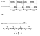
- Figur 4
- die Aufteilung der Rechenzeit auf die beiden asynchronen Prozesse des ASI-Masters und des Verarbeitungsrechners bei der Realisierung des ASI-Steuermasters mit einem einzigen Controller und
- Figur 5
- ein Beispieldiagramm für den Datenaustausch.
- E/S =
- Ende des Verarbeitungsrechnerzyklusses und Start eines neuen Verarbeitungsrechnerzyklusses
- D =
- Datenaustausch zwischen ASI-Master und Verarbeitungsrechner
- A =
- Abarbeitung des Verarbeitungsrechners
- =

- Zeitscheiben des Verarbeitungsrechners
Claims (6)
- Verfahren zum Steuern und Aktivieren von miteinander mittels eines Bussystems vernetzten binären Sensoren (6) und/oder Aktuatoren (ASI-Slaves), wobei die Bedienung des Bussystems von einem ASI-Master (1) und die Verarbeitung der ASI-Daten von einem Verarbeitungsrechner (2) durchgeführt wird und ASI-Master (1) und Verarbeitungsrechner (2) ASI-Daten und ASI-Flags miteinander austauschen, dadurch gekennzeichnet,
dass zur Sicherstellung der Konsistenz zwischen ASI-Daten und ASI-Flags der ASI-Master (1) die ASI-Daten und die ASI-Flags vor der Übertragung zum Verarbeitungsrechner (2) einfriert, also nicht mehr verändert, und der ASI-Master (1) die dadurch zueinander konsistenten ASI-Daten und die ASI-Flags zum gleichen Zeitpunkt oder zu verschiedenen Zeiten zusammen in einer Funktion oder in verschiedenen Funktionen an den Verarbeitungsrechner (2) überträgt. - Verfahren nach Anspruch 1, dadurch gekennzeichnet,
dass der ASI-Master (1) zuerst die ASI-Daten und anschließend die ASI-Flags überträgt und dabei sicherstellt, dass die ASI-Flags während der Abarbeitung der Übertragungsfunktion nicht auf "ok" sondern nur auf "false" gesetzt werden können. - Verfahren nach Anspruch 1 oder 2, dadurch gekennzeichnet,
dass der ASI-Master (1) die ASI-Daten und die ASI-Flags zum gleichen Zeitpunkt oder zu verschiedenen Zeiten intern zwischenspeichert und während der Übertragung der ASI-Daten und der ASI-Flags zum Verarbeitungsrechner (2) dieselben nicht mehr ändert. - Verfahren nach einem der vorherigen Ansprüche,
dadurch gekennzeichnet,
dass der ASI-Master (1) die ASI-Flags in einer Funktion prüft und bei fehlerfreiem Zustand auf "ok" setzt, wobei diese Funktion nicht asynchron zur Übertragung der ASI-Daten und ASI-Flags zum Verarbeitungsrechner (2) bearbeitet wird. - Verfahren nach einem der vorherigen Ansprüche,
dadurch gekennzeichnet,
dass bei einer Fehlererkennung durch den ASI-Master (1) ein zusätzliches Fehlerbit gesetzt wird, welches nur vom ASI-Master (1) gesetzt werden und nur vom Verarbeitungsrechner (2) gelöscht bzw. quittiert werden kann, und Fehler gespeichert werden, wobei durch das Speichern von Fehlern durch die Verarbeitungsrechnersoftware (12) eine Konsistenz der ASI-Daten beim Datenaustausch zwischen dem Verarbeitungsrechnern (2) und dem ASI-Master (1) erreicht wird. - Vorrichtung zum Steuern und Aktivieren von miteinander mittels eines Bussystems vernetzten binären Sensoren (6) und/oder Aktuatoren (ASI-Slaves), wobei die Bedienung des Bussystems von einem ASI-Master (1) und die Verarbeitung der ASI-Daten von einem Verarbeitungsrechner (2) durchgeführt wird und ASI-Master (1) und Verarbeitungsrechner (2) ASI-Daten und ASI-Flags miteinander austauschen, dadurch gekennzeichnet,
dass zur Sicherstellung der Konsistenz zwischen den ASI-Daten und den ASI-Flags die Vorrichtung die ASI-Daten und die ASI-Flags vor der Übertragung zum Verarbeitungsrechner (2) einzufrieren imstande ist, also nicht mehr verändert, und und der ASI-Master (1) die dadurch zueinander konsistenten ASI-Daten und die ASI-Flags zum gleichen Zeitpunkt oder zu verschiedenen Zeiten zusammen in einer Funktion oder in verschiedenen Funktionen an den Verarbeitungsrechner (2) überträgt.
Applications Claiming Priority (3)
| Application Number | Priority Date | Filing Date | Title |
|---|---|---|---|
| DE4433013A DE4433013A1 (de) | 1994-09-15 | 1994-09-15 | Verfahren und Vorrichtung zur Steuerung und Aktivierung von miteinander mittels eines Bussystems vernetzten Sensoren und/oder Aktuatoren |
| DE4433013 | 1994-09-15 | ||
| EP95931135A EP0782722B1 (de) | 1994-09-15 | 1995-09-14 | Verfahren und vorrichtung zur steuerung und aktivierung von miteinander mittels eines bussystems vernetzten sensoren und/oder aktuatoren |
Related Parent Applications (2)
| Application Number | Title | Priority Date | Filing Date |
|---|---|---|---|
| EP95931135A Division EP0782722B1 (de) | 1994-09-15 | 1995-09-14 | Verfahren und vorrichtung zur steuerung und aktivierung von miteinander mittels eines bussystems vernetzten sensoren und/oder aktuatoren |
| EP95931135.8 Division | 1996-03-21 |
Publications (3)
| Publication Number | Publication Date |
|---|---|
| EP0791874A2 EP0791874A2 (de) | 1997-08-27 |
| EP0791874A3 EP0791874A3 (de) | 1998-01-14 |
| EP0791874B1 true EP0791874B1 (de) | 1999-06-16 |
Family
ID=6528381
Family Applications (2)
| Application Number | Title | Priority Date | Filing Date |
|---|---|---|---|
| EP95931135A Expired - Lifetime EP0782722B1 (de) | 1994-09-15 | 1995-09-14 | Verfahren und vorrichtung zur steuerung und aktivierung von miteinander mittels eines bussystems vernetzten sensoren und/oder aktuatoren |
| EP97201131A Expired - Lifetime EP0791874B1 (de) | 1994-09-15 | 1995-09-14 | Verfahren und Vorrichtung zum Steuern von binären Sensoren und/oder Aktuatoren |
Family Applications Before (1)
| Application Number | Title | Priority Date | Filing Date |
|---|---|---|---|
| EP95931135A Expired - Lifetime EP0782722B1 (de) | 1994-09-15 | 1995-09-14 | Verfahren und vorrichtung zur steuerung und aktivierung von miteinander mittels eines bussystems vernetzten sensoren und/oder aktuatoren |
Country Status (3)
| Country | Link |
|---|---|
| EP (2) | EP0782722B1 (de) |
| DE (4) | DE4433013A1 (de) |
| WO (1) | WO1996008753A1 (de) |
Families Citing this family (16)
| Publication number | Priority date | Publication date | Assignee | Title |
|---|---|---|---|---|
| DE19710137B4 (de) * | 1996-03-14 | 2010-07-15 | Jochen Bihl | Verfahren und Vorrichtung zur Erweiterung der räumlichen Ausdehnung bei Sensor-Aktuator-Bussystemen |
| DE19616827C1 (de) * | 1996-04-26 | 1998-01-08 | Siemens Ag | Verfahren und Applikationseinrichtung zur Anzeige und Alarmierung von Meßwerten an Kommunikationsendgeräten |
| DE29610157U1 (de) * | 1996-06-10 | 1996-08-14 | Siemens Ag | Mehrfachsensor |
| KR100202706B1 (ko) * | 1996-10-05 | 1999-06-15 | 이종수 | 피엘씨 리모트 시스템의 기동시간 동기화 및 비상상태 출력 제어방법 |
| DE29714454U1 (de) * | 1997-08-13 | 1997-10-23 | Festo Ag & Co | Regelanordnung zur Regelung von wenigstens einem an einem Bussystem angeschlossenen Positionierantrieb, insbesondere pneumatischen Positionierantrieb |
| DE19735015B4 (de) * | 1997-08-13 | 2016-11-24 | Volkswagen Ag | Verfahren und Vorrichtung für Sicherheitsstrategien in Kraftfahrzeugen |
| DE19814102C2 (de) | 1998-03-30 | 1999-05-12 | Siemens Ag | Datenübertragungsverfahren |
| DE19831405A1 (de) | 1998-07-13 | 2000-01-20 | Siemens Ag | Steuerungssystem mit einem Personalcomputer |
| DE19840562B4 (de) * | 1998-09-07 | 2007-06-28 | Phoenix Contact Gmbh & Co. Kg | Sicherheitsbezogenes Steuer- und Datenübertragungssystem |
| DE19908230A1 (de) * | 1999-02-25 | 2000-08-31 | Heidelberger Druckmasch Ag | Vorrichtung zur Überwachung von sicherheitsrelevanten Vorgängen an Maschinen |
| DE19924201C2 (de) * | 1999-05-27 | 2001-05-10 | Sew Eurodrive Gmbh & Co | Verfahren und Vorrichtung zur Drehzahl- und/oder Drehrichtungserfassung von Motoren |
| DE19939567B4 (de) | 1999-08-20 | 2007-07-19 | Pilz Gmbh & Co. Kg | Vorrichtung zum Steuern von sicherheitskritischen Prozessen |
| DE10127264A1 (de) * | 2001-06-05 | 2002-12-12 | Siemens Ag | Verfahren zur Unterstützung des unterbrechbaren, geschachtelten konsistenten Datenaustausches |
| DE10152216B4 (de) * | 2001-10-23 | 2006-01-26 | Siemens Ag | Verfahren und Anordnung zum Überwachen eines Bus-Systems |
| DE102004040449B4 (de) * | 2004-08-20 | 2009-02-26 | Siemens Ag | Automatisierungseinrichtung mit einer CPU- und einer Master-Einheit |
| CN115542792A (zh) * | 2022-08-31 | 2022-12-30 | 东莞市瑚谷机械电子科技有限公司 | 以单片机为核心的asi通迅控制从站模块实现方法 |
Family Cites Families (1)
| Publication number | Priority date | Publication date | Assignee | Title |
|---|---|---|---|---|
| US4058711A (en) * | 1976-04-16 | 1977-11-15 | Cincinnati Milacron Inc. | Asynchronous dual function multiprocessor machine control |
-
1994
- 1994-09-15 DE DE4433013A patent/DE4433013A1/de not_active Withdrawn
-
1995
- 1995-09-14 WO PCT/DE1995/001261 patent/WO1996008753A1/de active IP Right Grant
- 1995-09-14 EP EP95931135A patent/EP0782722B1/de not_active Expired - Lifetime
- 1995-09-14 DE DE59506250T patent/DE59506250D1/de not_active Expired - Lifetime
- 1995-09-14 EP EP97201131A patent/EP0791874B1/de not_active Expired - Lifetime
- 1995-09-14 DE DE19581005T patent/DE19581005D2/de not_active Ceased
- 1995-09-14 DE DE59502616T patent/DE59502616D1/de not_active Expired - Lifetime
Also Published As
| Publication number | Publication date |
|---|---|
| EP0791874A2 (de) | 1997-08-27 |
| EP0782722B1 (de) | 1998-06-17 |
| DE59502616D1 (de) | 1998-07-23 |
| DE59506250D1 (de) | 1999-07-22 |
| EP0791874A3 (de) | 1998-01-14 |
| EP0782722A1 (de) | 1997-07-09 |
| WO1996008753A1 (de) | 1996-03-21 |
| DE19581005D2 (de) | 1998-02-05 |
| DE4433013A1 (de) | 1996-03-28 |
Similar Documents
| Publication | Publication Date | Title |
|---|---|---|
| EP0791874B1 (de) | Verfahren und Vorrichtung zum Steuern von binären Sensoren und/oder Aktuatoren | |
| EP0824231B1 (de) | Fertigungsanlage | |
| EP2182418B1 (de) | Verfahren und Vorrichtung zum Zugreifen auf ein Funktionsmodul eines Automatiersierungssystems | |
| DE102006047026B4 (de) | Verfahren und System zum redundanten Ansteuern einer Slaveeinrichtung | |
| EP1860564A1 (de) | Verfahren und Vorrichtung zum Austausch von Daten auf Basis des OPC-Kommunikationsprotokolls zwischen redundanten Prozessautomatisierungskomponenten | |
| DE19502499A1 (de) | Bussystem zur Steuerung und Aktivierung von miteinander vernetzten ASI-Slaves, vorzugsweise binäre Sensoren oder Eingangsmodule und/oder Ausgangsmodule oder Aktuatoren eines Aktuator-Sensor-Interface | |
| EP1699203B1 (de) | Modulares numerisches steuergerät | |
| DE102007026678A1 (de) | Verfahren zum Austausch eines defekten Feldgerätes gegen ein neues Feldgerät in einem über digitalen Feldbus kommunizierenden System, insbesondere Automatisierungssystem | |
| DE19744071B4 (de) | Eine programmierbare Logiksteuervorrichtung verwendendes Steuerungssystem | |
| DE19814102C2 (de) | Datenübertragungsverfahren | |
| EP1296207B1 (de) | HMI Gerät und Verfahren zur Bedienung einer technischen Einrichtung, Automatisierungssystem mit HMI Gerät und Computerprogrammprodukt mit Programm zur Durchführung des Verfahrens in einem HMI Gerät oder Automatisierungssystem | |
| EP2422248B1 (de) | System und verfahren zum verteilen von projektdaten einer sicherheitssteuerung einer automatisierten anlage auf die steuerungskomponenten | |
| DE19842593C2 (de) | Verfahren zum Betrieb eines Busmasters an einem Feldbus | |
| EP0825502B1 (de) | Steuerungssystem | |
| EP2026147A1 (de) | Verfahren zum Übermitteln von Telegrammen zwischen einer Steuereinrichtung und einem Peripherieelement über ein Zwischengerät | |
| EP1454201B1 (de) | Engineeringsystem und automatisierungssystem | |
| EP2806316B1 (de) | Verfahren zum Betreiben eines Automatisierungssystems | |
| DE3534465A1 (de) | Verbundsystem speicherprogrammierbarer steuerungen | |
| WO2004036324A1 (de) | Verfahren und vorrichtung zur prozessautomatisierung mit redundanten steuergeräten zur ansteuerung von peripheriegeräten über ein bussystem | |
| DE10357797A1 (de) | Peripherieeinheit für ein redundantes Steuersystem | |
| EP1282019A2 (de) | Verfahren und Vorrichtung zur -berwachung einer insbesondere speicherprogrammierbaren Steuerung | |
| EP3557342B1 (de) | Verfahren zur programmierung einer steuerung | |
| DE3928998A1 (de) | Speicherprogrammierbare steuerung | |
| WO2005078537A2 (de) | Projektierungsverfahren für ein automatisierungssystem | |
| DE102017209163A1 (de) | System zur steuerung einer industriellen anlage und verfahren zur sicheren/nichtsicheren kommunikation zwischen mindestens drei steuereinrichtungen |
Legal Events
| Date | Code | Title | Description |
|---|---|---|---|
| PUAI | Public reference made under article 153(3) epc to a published international application that has entered the european phase |
Free format text: ORIGINAL CODE: 0009012 |
|
| 17P | Request for examination filed |
Effective date: 19970429 |
|
| AC | Divisional application: reference to earlier application |
Ref document number: 782722 Country of ref document: EP |
|
| AK | Designated contracting states |
Kind code of ref document: A2 Designated state(s): CH DE FR GB IT LI |
|
| PUAL | Search report despatched |
Free format text: ORIGINAL CODE: 0009013 |
|
| AK | Designated contracting states |
Kind code of ref document: A3 Designated state(s): CH DE FR GB IT LI |
|
| 17Q | First examination report despatched |
Effective date: 19980113 |
|
| GRAG | Despatch of communication of intention to grant |
Free format text: ORIGINAL CODE: EPIDOS AGRA |
|
| GRAG | Despatch of communication of intention to grant |
Free format text: ORIGINAL CODE: EPIDOS AGRA |
|
| GRAH | Despatch of communication of intention to grant a patent |
Free format text: ORIGINAL CODE: EPIDOS IGRA |
|
| GRAH | Despatch of communication of intention to grant a patent |
Free format text: ORIGINAL CODE: EPIDOS IGRA |
|
| GRAA | (expected) grant |
Free format text: ORIGINAL CODE: 0009210 |
|
| AC | Divisional application: reference to earlier application |
Ref document number: 782722 Country of ref document: EP |
|
| AK | Designated contracting states |
Kind code of ref document: B1 Designated state(s): CH DE FR GB IT LI |
|
| PG25 | Lapsed in a contracting state [announced via postgrant information from national office to epo] |
Ref country code: IT Free format text: LAPSE BECAUSE OF FAILURE TO SUBMIT A TRANSLATION OF THE DESCRIPTION OR TO PAY THE FEE WITHIN THE PRE;WARNING: LAPSES OF ITALIAN PATENTS WITH EFFECTIVE DATE BEFORE 2007 MAY HAVE OCCURRED AT ANY TIME BEFORE 2007. THE CORRECT EFFECTIVE DATE MAY BE DIFFERENT FROM THE ONE RECORDED.SCRIBED TIME-LIMIT Effective date: 19990616 Ref country code: GB Free format text: LAPSE BECAUSE OF FAILURE TO SUBMIT A TRANSLATION OF THE DESCRIPTION OR TO PAY THE FEE WITHIN THE PRESCRIBED TIME-LIMIT Effective date: 19990616 Ref country code: FR Free format text: LAPSE BECAUSE OF FAILURE TO SUBMIT A TRANSLATION OF THE DESCRIPTION OR TO PAY THE FEE WITHIN THE PRESCRIBED TIME-LIMIT Effective date: 19990616 |
|
| REG | Reference to a national code |
Ref country code: CH Ref legal event code: EP |
|
| REF | Corresponds to: |
Ref document number: 59506250 Country of ref document: DE Date of ref document: 19990722 |
|
| PG25 | Lapsed in a contracting state [announced via postgrant information from national office to epo] |
Ref country code: LI Free format text: LAPSE BECAUSE OF NON-PAYMENT OF DUE FEES Effective date: 19990930 Ref country code: CH Free format text: LAPSE BECAUSE OF NON-PAYMENT OF DUE FEES Effective date: 19990930 |
|
| EN | Fr: translation not filed | ||
| GBV | Gb: ep patent (uk) treated as always having been void in accordance with gb section 77(7)/1977 [no translation filed] |
Effective date: 19990616 |
|
| PLBQ | Unpublished change to opponent data |
Free format text: ORIGINAL CODE: EPIDOS OPPO |
|
| PLBI | Opposition filed |
Free format text: ORIGINAL CODE: 0009260 |
|
| PLBF | Reply of patent proprietor to notice(s) of opposition |
Free format text: ORIGINAL CODE: EPIDOS OBSO |
|
| 26 | Opposition filed |
Opponent name: LEUZE ELECTRONIC GMBH + CO Effective date: 20000313 |
|
| REG | Reference to a national code |
Ref country code: CH Ref legal event code: PL |
|
| PLBF | Reply of patent proprietor to notice(s) of opposition |
Free format text: ORIGINAL CODE: EPIDOS OBSO |
|
| PLBF | Reply of patent proprietor to notice(s) of opposition |
Free format text: ORIGINAL CODE: EPIDOS OBSO |
|
| PLBO | Opposition rejected |
Free format text: ORIGINAL CODE: EPIDOS REJO |
|
| RTI2 | Title (correction) |
Free format text: METHOD AND APPARATUS FOR CONTROLLING BINARY SENSORS AND/OR ACTUATORS |
|
| PLBN | Opposition rejected |
Free format text: ORIGINAL CODE: 0009273 |
|
| STAA | Information on the status of an ep patent application or granted ep patent |
Free format text: STATUS: OPPOSITION REJECTED |
|
| 27O | Opposition rejected |
Effective date: 20011025 |
|
| PGFP | Annual fee paid to national office [announced via postgrant information from national office to epo] |
Ref country code: DE Payment date: 20120813 Year of fee payment: 18 |
|
| REG | Reference to a national code |
Ref country code: DE Ref legal event code: R119 Ref document number: 59506250 Country of ref document: DE Effective date: 20140401 |
|
| PG25 | Lapsed in a contracting state [announced via postgrant information from national office to epo] |
Ref country code: DE Free format text: LAPSE BECAUSE OF NON-PAYMENT OF DUE FEES Effective date: 20140401 |