EP1692578B1 - Peripheral unit for a redundant control system - Google Patents
Peripheral unit for a redundant control system Download PDFInfo
- Publication number
- EP1692578B1 EP1692578B1 EP04803758A EP04803758A EP1692578B1 EP 1692578 B1 EP1692578 B1 EP 1692578B1 EP 04803758 A EP04803758 A EP 04803758A EP 04803758 A EP04803758 A EP 04803758A EP 1692578 B1 EP1692578 B1 EP 1692578B1
- Authority
- EP
- European Patent Office
- Prior art keywords
- output current
- peripheral unit
- ist
- actual output
- soll
- Prior art date
- Legal status (The legal status is an assumption and is not a legal conclusion. Google has not performed a legal analysis and makes no representation as to the accuracy of the status listed.)
- Not-in-force
Links
- 230000002093 peripheral effect Effects 0.000 title claims description 49
- 230000008859 change Effects 0.000 claims description 18
- 230000001939 inductive effect Effects 0.000 claims description 8
- 230000001360 synchronised effect Effects 0.000 claims 1
- 238000000034 method Methods 0.000 description 9
- 230000008569 process Effects 0.000 description 9
- 238000011156 evaluation Methods 0.000 description 6
- 230000008878 coupling Effects 0.000 description 3
- 238000010168 coupling process Methods 0.000 description 3
- 238000005859 coupling reaction Methods 0.000 description 3
- 230000003111 delayed effect Effects 0.000 description 2
- 238000001514 detection method Methods 0.000 description 2
- 238000010586 diagram Methods 0.000 description 2
- 238000012544 monitoring process Methods 0.000 description 2
- 230000001960 triggered effect Effects 0.000 description 2
- 238000013461 design Methods 0.000 description 1
- 238000005516 engineering process Methods 0.000 description 1
- 238000012545 processing Methods 0.000 description 1
Images

Classifications
-
- G—PHYSICS
- G05—CONTROLLING; REGULATING
- G05B—CONTROL OR REGULATING SYSTEMS IN GENERAL; FUNCTIONAL ELEMENTS OF SUCH SYSTEMS; MONITORING OR TESTING ARRANGEMENTS FOR SUCH SYSTEMS OR ELEMENTS
- G05B19/00—Programme-control systems
- G05B19/02—Programme-control systems electric
- G05B19/04—Programme control other than numerical control, i.e. in sequence controllers or logic controllers
- G05B19/05—Programmable logic controllers, e.g. simulating logic interconnections of signals according to ladder diagrams or function charts
- G05B19/058—Safety, monitoring
-
- G—PHYSICS
- G05—CONTROLLING; REGULATING
- G05B—CONTROL OR REGULATING SYSTEMS IN GENERAL; FUNCTIONAL ELEMENTS OF SUCH SYSTEMS; MONITORING OR TESTING ARRANGEMENTS FOR SUCH SYSTEMS OR ELEMENTS
- G05B2219/00—Program-control systems
- G05B2219/10—Plc systems
- G05B2219/11—Plc I-O input output
- G05B2219/1185—Feedback of output status to input module and compare with command
-
- G—PHYSICS
- G05—CONTROLLING; REGULATING
- G05B—CONTROL OR REGULATING SYSTEMS IN GENERAL; FUNCTIONAL ELEMENTS OF SUCH SYSTEMS; MONITORING OR TESTING ARRANGEMENTS FOR SUCH SYSTEMS OR ELEMENTS
- G05B2219/00—Program-control systems
- G05B2219/10—Plc systems
- G05B2219/14—Plc safety
- G05B2219/14038—Fault in I-O racks, point level
Definitions
- the invention relates to a peripheral unit for a redundant control system having a first and a second control computer, wherein the peripheral unit control data from one of the control computer can be supplied, which represent a desired output current for driving an inductive load, wherein by the peripheral unit of the inductive load via an output of the peripheral unit and an actual output current can be fed via a line.
- the invention relates to a redundant control system.
- the Siemens catalog ST 70 Chapter 1 and 5, Edition 2003, describes the SIMATIC S7-400H fault-tolerant automation system with a redundant design and the IM153-2 interface module, which can be used to connect an ET 200M peripheral unit as a slave in redundant PROFIBUS-DP systems can be used with the SIMATIC S7-400H automation system.
- the fault-tolerant SIMATIC S7-400H continues to operate even if parts of the controller have failed due to one or more errors. It has redundant central functions and is built with two separate central devices as control computer. The two control computers execute the same processing programs cyclically and synchronously. They monitor each other and independently determine which control computer is active, ie actually controls the process via its output data. For this purpose, data is exchanged via a redundancy coupling between the two control computers.
- Process output data by which the signals to be output to the actuators from the peripheral unit are given, are offered to the peripheral unit in the undisturbed case via both field buses, but it only evaluates the control data received from one of the field buses.
- the respective connected control computer can thus be referred to as the active control computer.
- the invention has for its object to provide a peripheral unit for a redundant control system which detects faults at their outputs as quickly as possible.
- a redundant control system is to be specified, by means of which an inductive load can be controlled substantially without interference.
- the actual output current is detected and this is compared with the setpoint output current, a short circuit can be detected at the peripheral output due to the evaluation of the comparison result.
- the rate of change of the actual output current by further detecting the rate of change of the actual output current and comparing it with the rate of change of the desired output current, an interruption of the line between the peripheral output and the actuator and thus a total failure of the actuator can be detected quickly.
- the actual output current breaks down abruptly in such a case, without the setpoint has changed. It is taken into account that the inductive load has a very high inductance and thus a change in current at a given inductance and supply voltage of the analog output only delayed after a few milliseconds is effective.
- the availability of the redundant control system is increased because a fault in the output of the peripheral unit is quickly detected and reported, which can be done quickly to a redundant branch of the control system, consisting of control computer and peripheral unit.
- the time interval is z. B. predetermined such that a brief break (t ⁇ 20 milliseconds) of the output current is detected and a switchover takes place.
- a brief break t ⁇ 20 milliseconds
- a fast detection and switching is required; because a collapse of the drive current for a period of about 20 milliseconds already causes a power dip of several megawatts.
- the limit is z. B. predetermined such that even small caused by hardware errors deviations are detected.
- a current mirror circuit is provided, whereby a simple detection of the actual output current is possible.
- FIG. 3 in which a known per se redundant control system is shown.
- the redundant control system is constructed in accordance with a 1 of 2 principle and comprises a first redundancy unit with a first control computer 1 and a first peripheral unit 4 and a second redundancy unit with a second control computer 2 and a peripheral unit 5.
- Sensors 8 detect process signals of a technical process to be controlled from the peripheral units 4, 5 are read in via lines 10 and are transmitted via suitable serial or parallel buses 6, 7 to the control computers 1, 2 in the form of digital signals.
- the control computers 1, 2 process these signals into corresponding control signals for actuators 9, wherein only one of the redundancy units transmits these control signals to the actuators 9 via a line 11.
- the redundancy units operate according to a master-reserve operation, which means that only one redundancy unit is active, while the other is switched to passive. Only the active redundancy unit controls the actuators 9 via its peripheral unit, the other redundancy unit only transmits a zero signal to its peripheral unit.
- a redundancy coupling 3 is provided, via which the redundancy units are interconnected.
- the active redundancy unit indicates the disturbance via the redundancy coupling 3 of the passive redundancy unit, whereby the currently passive redundancy unit changes to the active mode, ie this redundancy unit is activated and takes over the master mode , on the other hand, becomes the currently active redundancy unit switched to passive and changes to the reserve mode.
- a change of the master shaft must take place in such a way that the control signals are transmitted to the actuators essentially continuously and as far as possible without signal collapses.
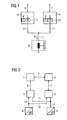
- FIG. 1 In this context is on FIG. 1 referenced, in which a redundant control of an actuator in the form of an inductive load is shown.
- the in the FIGS. 1 and 2 The same parts shown are provided with the same reference numerals.
- the redundantly constructed peripheral units 4, 5 have parallel-connected analog outputs 12, 13, wherein, depending on which redundancy unit operates in master mode, either the output 12 of the peripheral unit 4 or the output 13 of the peripheral unit 5 a current I an actuator 9 ' supplies. In the event that the redundancy unit, to which the peripheral unit 4 is assigned, is active, the peripheral unit 4 supplies the current I to the actuator 9 'via its output 12.
- the redundancy unit including the peripheral unit 5 is passive in this case, whereby the peripheral unit 5 does not supply power to the actuator 9 '.
- the peripheral unit 4 is switched to passive if the peripheral unit 5 transmits the current I to the actuator 9 '.
- FIG. 2 In this context is on FIG. 2 referenced, in which a function diagram of an evaluation algorithm of a peripheral unit is shown.
- a difference generator 14 determines the difference between an actual output current I ist and a desired output current I soll , wherein the amount of this difference determined by an absolute value generator 15 is compared with a predefinable limit value Gw1 of a limit value adjuster 16 over a predefinable time interval ⁇ of a delay element 17.
- an error signal F is generated via an AND or OR gate 23, which indicates to a control computer a fault in an analog output of a peripheral unit.
- the limit value Gw1 is set very small. Even in the event that the rate of change (.DELTA.I is / .DELTA.t) of the actual output current I is substantially not coincident with the rate of change (.DELTA.I soll / .DELTA.t) of the target output current I soll , an error F is displayed to the control computer, This error message indicates that there is a total hardware failure of the analog output of the peripheral unit. This failure can z. B. by a breakage of the line 11 between the peripheral unit 4, 5 and the actuator 9 '( FIG. 1 ).
- the rate of change of the actual output current I is and the target output current I soll detect elements 18, 19, wherein an error signal F via the AND or OR gate 23 is then triggered, if an AND gate 22 detects that, on the one hand, the rate of change of the actual Output current I is negative, this falls below a predetermined limit Gw2 a limit value 19 and on the other hand, substantially at the same time as the change of the actual output current I is no change in the target output current I should have been effected.
- the actuator 9 ' has a very high inductance L as the electromagnetic system.
- a deviation from the nominal and actual output current is not forwarded unfiltered to the control computer, but is first filtered over several time stages. Only when a deviation is longer than the time .DELTA.t, an error message is triggered and causes a change.
Landscapes
- Physics & Mathematics (AREA)
- General Physics & Mathematics (AREA)
- Engineering & Computer Science (AREA)
- Automation & Control Theory (AREA)
- Safety Devices In Control Systems (AREA)
Description
Die Erfindung betrifft eine Peripherieeinheit für ein redundantes Steuersystem, welches einen ersten und einen zweiten Steuerrechner aufweist, wobei der Peripherieeinheit Steuerdaten von einem der Steuerrechner zuführbar sind, welche einen Soll-Ausgangsstrom zum Ansteuern einer induktiven Last repräsentieren, wobei durch die Peripherieeinheit der induktiven Last über einen Ausgang der Peripherieeinheit und über eine Leitung ein Ist-Ausgangsstrom zuführbar ist. Darüber hinaus betrifft die Erfindung ein redundantes Steuersystem.The invention relates to a peripheral unit for a redundant control system having a first and a second control computer, wherein the peripheral unit control data from one of the control computer can be supplied, which represent a desired output current for driving an inductive load, wherein by the peripheral unit of the inductive load via an output of the peripheral unit and an actual output current can be fed via a line. Moreover, the invention relates to a redundant control system.
Aus dem Siemens-Katalog ST 70, Kapitel 1 und 5, Ausgabe 2003 sind das hochverfügbare Automatisierungssystem SIMATIC S7-400H mit redundant ausgelegtem Aufbau sowie die Anschaltung IM153-2, die zum Anschluss einer Peripherieeinheit ET 200M als Slave in redundanten PROFIBUS-DP-Systemen mit dem Automatisierungssystem SIMATIC S7-400H einsetzbar ist, bekannt.The Siemens catalog ST 70,
In vielen Bereichen der Automatisierungstechnik werden immer höhere Anforderungen an die Verfügbarkeit und damit an die Ausfallsicherheit der Automatisierungssysteme gestellt. Es sind Bereiche, in denen ein Anlagenstillstand sehr hohe Kosten verursachen würde. Hier können nur redundante Systeme den Anforderungen an die Verfügbarkeit gerecht werden. Beispielsweise die hochverfügbare SIMATIC S7-400H arbeitet auch dann weiter, wenn durch einen oder mehrere Fehler Teile der Steuerung ausgefallen sind. Sie besitzt redundant ausgelegte zentrale Funktionen und ist mit zwei getrennten Zentralgeräten als Steuerrechner aufgebaut. Die beiden Steuerrechner arbeiten zyklisch und synchron die gleichen Verarbeitungsprogramme ab. Sie überwachen sich gegenseitig und legen selbständig fest, welcher Steuerrechner aktiv ist, d. h. tatsächlich über seine Ausgabedaten den Prozess steuert. Hierzu werden Daten über eine Redundanzkopplung zwischen den beiden Steuerrechnern ausgetauscht. Redundant ausgebildete dezentrale Peripherieeinheiten ET 200M, in welche je nach Einsatzfall digitale Ein-/Ausgabebaugruppen gesteckt sind, sind jeweils mit einem Feldbus PROFIBUS-DP an die einen Steuerrechner angeschlossen. Mit Hilfe von Messumformern oder -gebern gewonnene Prozesseingangsinformationen werden durch die Peripherieeinheit an beide Steuerrechner weitergeleitet. Beim so genannten "Hot Stand By"-Betrieb arbeiten die beiden Steuerrechner im ungestörten Fall gleichzeitig dasselbe Steuerprogramm ab, es ist jedoch nur ein Steuerrechner aktiv, d. h., nur die Ausgabedaten eines Steuerrechners werden zur Steuerung des Prozesses weiterverarbeitet. Im Fehlerfall übernimmt das intakte Gerät allein die Steuerung des Prozesses. Dazu erhalten die Geräte automatisch das gleiche Anwenderprogramm, die gleichen Datenbausteine, die gleichen Prozessabbildinhalte sowie die gleichen internen Daten, wie z. B. Zeiten, Zähler, Merker usw. Dadurch sind beide Geräte immer auf dem aktuellen Stand und können im Fehlerfall jederzeit die Steuerung alleine weiterführen. Prozessausgabedaten, durch welche die an die Stellglieder von der Peripherieeinheit auszugebenden Signale vorgegeben werden, werden der Peripherieeinheit im ungestörten Fall über beide Feldbusse angeboten, sie wertet jedoch nur die von einem der Feldbusse empfangenen Steuerdaten aus. Der jeweils angeschlossene Steuerrechner kann somit als der aktive Steuerrechner bezeichnet werden.
Um z. B. einen reibungslosen Betrieb einer an die Analogausgänge der Peripherieeinheiten angeschlossenen Turbine zu gewährleisten, ist es erforderlich, eine Störung an diesen Analogausgängen schnell zu erfassen und anzuzeigen, wodurch eine Umschaltung auf die ungestörte Peripherieeinheit rasch möglich ist, welche die Ansteuerung der Turbine übernimmt.In many areas of automation technology ever higher demands are placed on the availability and thus on the reliability of the automation systems. These are areas where a plant shutdown would cause very high costs. Only redundant systems can meet the availability requirements here. For example, the fault-tolerant SIMATIC S7-400H continues to operate even if parts of the controller have failed due to one or more errors. It has redundant central functions and is built with two separate central devices as control computer. The two control computers execute the same processing programs cyclically and synchronously. They monitor each other and independently determine which control computer is active, ie actually controls the process via its output data. For this purpose, data is exchanged via a redundancy coupling between the two control computers. Redundant trained distributed I / O units ET 200M, in each of which After digital I / O modules have been inserted, a PROFIBUS-DP fieldbus is connected to the one control computer. Process input information obtained with the aid of transducers or transmitters is forwarded by the peripheral unit to both control computers. In the case of the so-called "hot stand-by" operation, the two control computers simultaneously operate the same control program in the undisturbed case, but only one control computer is active, ie only the output data of a control computer are processed further to control the process. In the event of a fault, the intact device alone takes control of the process. In addition, the devices automatically receive the same user program, the same data blocks, the same process image contents as well as the same internal data, such as data. As times, counters, flags, etc. This means that both devices are always up to date and can always continue the control alone in case of error. Process output data, by which the signals to be output to the actuators from the peripheral unit are given, are offered to the peripheral unit in the undisturbed case via both field buses, but it only evaluates the control data received from one of the field buses. The respective connected control computer can thus be referred to as the active control computer.
To z. B. to ensure a smooth operation of a turbine connected to the analog outputs of the peripheral units, it is necessary to quickly detect and display a fault on these analog outputs, whereby a switch to the undisturbed peripheral unit is quickly possible, which takes over the control of the turbine.
Der Erfindung liegt die Aufgabe zugrunde, eine Peripherieeinheit für ein redundantes Steuersystem zu schaffen, welche Störungen an ihren Ausgängen möglichst schnell erkennt. Darüber hinaus ist ein redundantes Steuersystem anzugeben, durch welches eine induktive Last im Wesentlichen störungsfrei ansteuerbar ist.The invention has for its object to provide a peripheral unit for a redundant control system which detects faults at their outputs as quickly as possible. In addition, a redundant control system is to be specified, by means of which an inductive load can be controlled substantially without interference.
Diese Aufgabe wird im Hinblick auf die Peripherieeinheit durch die im kennzeichnenden Teil des Anspruchs 1 angegebenen Maßnahmen, im Hinblick auf das redundante Steuersystem durch die im Anspruch 3 angegebenen Maßnahmen gelöst.This object is achieved with regard to the peripheral unit by the measures indicated in the characterizing part of
Dadurch, dass der Ist-Ausgangsstrom erfasst und dieser mit dem Soll-Ausgangsstrom verglichen wird, kann aufgrund der Auswertung des Vergleichsergebnisses ein Kurzschluss am Peripherieausgang erkannt werden.
Darüber hinaus kann dadurch, dass ferner die Änderungsgeschwindigkeit des Ist-Ausgangsstroms erfasst und mit der Änderungsgeschwindigkeit des Soll-Ausgangsstroms verglichen wird, eine Unterbrechung der Leitung zwischen Peripherieausgang und Aktor und damit ein Totalausfall des Aktors schnell erkannt werden. Der Ist-Ausgangsstrom bricht in einem derartigen Fall schlagartig zusammen, ohne dass sich der Sollwert geändert hat. Dabei wird berücksichtigt, dass die induktive Last eine sehr hohe Induktivität aufweist und dadurch eine Stromänderung bei vorgegebener Induktivität und Versorgungsspannung des Analogausgangs erst verzögert nach einigen Millisekunden wirksam wird.Due to the fact that the actual output current is detected and this is compared with the setpoint output current, a short circuit can be detected at the peripheral output due to the evaluation of the comparison result.
In addition, by further detecting the rate of change of the actual output current and comparing it with the rate of change of the desired output current, an interruption of the line between the peripheral output and the actuator and thus a total failure of the actuator can be detected quickly. The actual output current breaks down abruptly in such a case, without the setpoint has changed. It is taken into account that the inductive load has a very high inductance and thus a change in current at a given inductance and supply voltage of the analog output only delayed after a few milliseconds is effective.
Die Verfügbarkeit des redundanten Steuersystems wird erhöht, da eine Störung am Ausgang der Peripherieeinheit schnell erkannt und gemeldet wird, wodurch eine rasche Umschaltung auf einen redundanten Zweig des Steuersystems, bestehend aus Steuerrechner und Peripherieeinheit, erfolgen kann. Das Zeitintervall wird z. B. derart vorgegeben, dass ein kurzzeitiger Einbruch (t < 20 Millisekunden) des Ausgangsstroms erfasst wird und eine Umschaltung erfolgt. Insbesondere für den Fall, dass eine Turbine angesteuert wird, ist bei einer Störung eines Ausgangs der Peripherieeinheit eine schnelle Erfassung und Umschaltung erforderlich; denn ein Einbruch des Ansteuerstroms für einen Zeitraum von ca. 20 Millisekunden bewirkt bereits einen Leistungseinbruch von mehreren Megawatt. Der Grenzwert wird z. B. derart vorgegeben, dass bereits kleine durch Hardwarestörungen bewirkte Abweichungen erkannt werden.The availability of the redundant control system is increased because a fault in the output of the peripheral unit is quickly detected and reported, which can be done quickly to a redundant branch of the control system, consisting of control computer and peripheral unit. The time interval is z. B. predetermined such that a brief break (t <20 milliseconds) of the output current is detected and a switchover takes place. In particular, in the case that a turbine is driven, in case of failure of an output of the peripheral unit, a fast detection and switching is required; because a collapse of the drive current for a period of about 20 milliseconds already causes a power dip of several megawatts. The limit is z. B. predetermined such that even small caused by hardware errors deviations are detected.
In einer Ausgestaltung der Erfindung ist eine Stromspiegelschaltung vorgesehen, wodurch eine einfache Erfassung des Ist-Ausgangsstromes möglich ist.In one embodiment of the invention, a current mirror circuit is provided, whereby a simple detection of the actual output current is possible.
Anhand der Zeichnung, in der ein Ausführungsbeispiel der Erfindung veranschaulicht ist, werden im Folgenden die Erfindung, deren Ausgestaltungen sowie Vorteile näher erläutert.Reference to the drawing, in which an embodiment of the invention is illustrated, the invention, the embodiments and advantages are explained in more detail below.
Es zeigen:
Figur 1- eine redundante Ansteuerung von Aktoren,
Figur 2- einen Funktionsplan eines Auswertealgorithmus und
- Figur 3
- ein redundantes Steuersystem.
- FIG. 1
- a redundant control of actuators,
- FIG. 2
- a function diagram of an evaluation algorithm and
- FIG. 3
- a redundant control system.
Es wird zunächst auf
In diesem Zusammenhang wird auf
Damit die Peripherieeinheiten 4, 5 Störungen an ihren Ausgängen möglichst schnell erkennen, sind die Peripherieeinheiten 4, 5 mit Mitteln versehen, welche jeweils den Ausgangsstrom ihrer Analogausgänge 12, 13 überwachen und Störungen den Steuerrechnern anzeigen. Dazu weist jede Peripherieeinheit 4, 5 eine Stromspiegelschaltung auf, welche ihren tatsächlichen Ausgangsstrom zunächst erfasst, dann digitalisiert und schließlich den digitalisierten Ist-Ausgangsstrom einem Auswertealgorithmus übermittelt. Der Auswertealgorithmus vergleicht diesen Ist-Ausgangsstrom mit einem der Peripherieeinheit durch den Steuerrechner vorgegebenen Soll-Ausgangsstrom, wobei der Auswertealgorithmus dem Steuerrechner eine Störung anzeigt, falls
- für ein vorgebbares Zeitintervall die Differenz zwischen dem Ist-Ausgangsstrom und dem Soll-Ausgangsstrom größer ist als ein vorgebbarer Grenzwert (Überwachung auf Kurzschluss) und/oder
- die Änderungsgeschwindigkeit des Ist-Ausgangsstroms im Wesentlichen nicht zeitgleich ist mit der Änderungsgeschwindigkeit des Soll-Ausgangsstroms (Überwachung auf Drahtbruch) .
- for a predeterminable time interval, the difference between the actual output current and the nominal output current is greater than a predefinable limit value (monitoring for short circuit) and / or
- the rate of change of the actual output current is substantially not coincident with the rate of change of the desired output current (wire break monitoring).
In diesem Zusammenhang wird auf
Auch für den Fall, dass die Änderungsgeschwindigkeit (ΔIist/Δt) des Ist-Ausgangsstroms Iist im Wesentlichen nicht zeitgleich erfolgt mit der Änderungsgeschwindigkeit (ΔIsoll/Δt) des Soll-Ausgangsstroms Isoll, wird ein Fehler F dem Steuerrechner angezeigt, wobei diese Fehleranzeige darauf hinweist, dass ein Totalausfall der Hardware des Analogausgangs der Peripherieeinheit vorliegt. Dieser Ausfall kann z. B. durch einen Bruch der Leitung 11 zwischen der Peripherieeinheit 4, 5 und dem Aktor 9' (
Damit "unberechtigte" Fehlermeldungen vermieden werden, wird eine Abweichung von Soll- und Ist-Ausgangsstrom nicht ungefiltert an den Steuerrechner weitergegeben, sondern wird zunächst über mehrere Zeitstufen gefiltert. Erst wenn eine Abweichung länger als die Zeit Δt ansteht, wird eine Fehlermeldung ausgelöst und eine Umschaltung bewirkt.In this context is on
Even in the event that the rate of change (.DELTA.I is / .DELTA.t) of the actual output current I is substantially not coincident with the rate of change (.DELTA.I soll / .DELTA.t) of the target output current I soll , an error F is displayed to the control computer, This error message indicates that there is a total hardware failure of the analog output of the peripheral unit. This failure can z. B. by a breakage of the
In order to avoid "unauthorized" error messages, a deviation from the nominal and actual output current is not forwarded unfiltered to the control computer, but is first filtered over several time stages. Only when a deviation is longer than the time .DELTA.t, an error message is triggered and causes a change.
Claims (3)
- Peripheral unit for a redundant control system, which features a first and a second control processor (1, 2), with control data which represents a setpoint output current (Isoll) for controlling an inductive load able to be supplied to the peripheral unit (4, 5) by one of the control processors (1, 2),
with an actual output current (Iist) able to be supplied by the peripheral unit (4, 5) to the inductive load (9) via an output (12, 13) of the peripheral unit (3, 4) and via a line, characterized in that the peripheral unit (4, 5) is provided with means which detect the actual output current (Iist) and compare the actual output current (Iist) with the setpoint output current (Isoll) and/or detect the speed of change of the actual output current (Iist) and compare it with the speed of change of the setpoint output current (Isoll), with the means indicating to the one control processor a fault of the output (12, 13) of the peripheral unit for the case in which- for a predeterminable time interval (r) the difference between the actual output current (Iist) and the setpoint output current (Isoll) is greater than a predeterminable limit value (Gw1) and/or- the speed of change of the actual output current (Iist) is essentially not synchronous with the speed of change of the setpoint output current (Isoll) . - Peripheral unit according to claim 1, characterized in that the means for detecting the actual output current is provided with a current mirror circuit.
- Redundant control system with a first and a second control processor, with each control processor (1, 2) being provided with a peripheral unit (4, 5) according to claim 1 or 2, and the peripheral units being able to be connected via a common connection point to an inductive load (9).
Applications Claiming Priority (2)
| Application Number | Priority Date | Filing Date | Title |
|---|---|---|---|
| DE2003157797 DE10357797A1 (en) | 2003-12-10 | 2003-12-10 | Peripheral unit for a redundant control system |
| PCT/EP2004/014116 WO2005057306A1 (en) | 2003-12-10 | 2004-12-10 | Peripheral unit for a redundant control system |
Publications (2)
| Publication Number | Publication Date |
|---|---|
| EP1692578A1 EP1692578A1 (en) | 2006-08-23 |
| EP1692578B1 true EP1692578B1 (en) | 2008-04-30 |
Family
ID=34672564
Family Applications (1)
| Application Number | Title | Priority Date | Filing Date |
|---|---|---|---|
| EP04803758A Not-in-force EP1692578B1 (en) | 2003-12-10 | 2004-12-10 | Peripheral unit for a redundant control system |
Country Status (5)
| Country | Link |
|---|---|
| EP (1) | EP1692578B1 (en) |
| CN (1) | CN100541363C (en) |
| DE (2) | DE10357797A1 (en) |
| ES (1) | ES2303651T3 (en) |
| WO (1) | WO2005057306A1 (en) |
Families Citing this family (5)
| Publication number | Priority date | Publication date | Assignee | Title |
|---|---|---|---|---|
| DE102007022631B3 (en) * | 2007-05-11 | 2008-12-18 | Phoenix Contact Gmbh & Co. Kg | Parameter monitoring for analog signal modules |
| EP2048555A1 (en) * | 2007-10-01 | 2009-04-15 | Siemens Aktiengesellschaft | Analogue output device with error recognition |
| DE102009022389A1 (en) * | 2009-05-22 | 2010-12-02 | Phoenix Contact Gmbh & Co. Kg | Control system for controlling a process |
| EP2280326B1 (en) * | 2009-07-09 | 2014-04-16 | Siemens Aktiengesellschaft | Power supply module for an automation system |
| EP3214512B1 (en) | 2016-03-02 | 2018-04-25 | Siemens Aktiengesellschaft | Redundant control system for an actuator and method for its redundant control |
Family Cites Families (5)
| Publication number | Priority date | Publication date | Assignee | Title |
|---|---|---|---|---|
| FR2703480B1 (en) * | 1993-03-30 | 1995-06-02 | Merlin Gerin | Analog security interface. |
| DE4312305C5 (en) * | 1993-04-15 | 2004-07-15 | Abb Patent Gmbh | Safety-related programmable logic controller |
| DE59308478D1 (en) * | 1993-10-11 | 1998-06-04 | Siemens Ag | Processing module for a modular automation system |
| DE10008434A1 (en) * | 2000-02-23 | 2001-09-20 | Phoenix Contact Gmbh & Co | Method and device for monitoring security in an automation control device includes an automation device with a controller and a central monitoring device with direct in- and output devices and a serial bus connection. |
| JP2003217294A (en) * | 2001-11-16 | 2003-07-31 | Fujitsu Ltd | Semiconductor memory device and redundancy judging method |
-
2003
- 2003-12-10 DE DE2003157797 patent/DE10357797A1/en not_active Withdrawn
-
2004
- 2004-12-10 CN CNB2004800415663A patent/CN100541363C/en not_active Expired - Fee Related
- 2004-12-10 WO PCT/EP2004/014116 patent/WO2005057306A1/en active IP Right Grant
- 2004-12-10 DE DE502004007013T patent/DE502004007013D1/de active Active
- 2004-12-10 ES ES04803758T patent/ES2303651T3/en active Active
- 2004-12-10 EP EP04803758A patent/EP1692578B1/en not_active Not-in-force
Also Published As
| Publication number | Publication date |
|---|---|
| DE502004007013D1 (en) | 2008-06-12 |
| CN100541363C (en) | 2009-09-16 |
| EP1692578A1 (en) | 2006-08-23 |
| WO2005057306A1 (en) | 2005-06-23 |
| CN1914570A (en) | 2007-02-14 |
| ES2303651T3 (en) | 2008-08-16 |
| DE10357797A1 (en) | 2005-08-04 |
Similar Documents
| Publication | Publication Date | Title |
|---|---|---|
| EP1297394B1 (en) | Redundant control system and control computer and peripheral unit for said control system | |
| EP3246771B1 (en) | Method for operating a redundant automation system | |
| EP2657797B1 (en) | Method for operating a redundant automation system | |
| DE102006047026B4 (en) | Method and system for redundantly controlling a slave device | |
| EP2817682B1 (en) | Method for the failsafe operation of a process control system with redundant control devices | |
| EP2857913B1 (en) | Redundant automation system | |
| DE4317729A1 (en) | Programmable control unit | |
| EP1743225B1 (en) | Redundant computerizing system comprising a master programmable automaton and a standby programmable automaton | |
| EP1860564A1 (en) | Method and device for exchanging data based on the OPC communication protocol between the redundant components of a process control system | |
| DE19744071B4 (en) | Control system using a programmable logic controller | |
| EP1092177B1 (en) | Controller or engine controller, engine and method for adjusting a control or drive system or an engine | |
| EP1699203A1 (en) | Modular numerical control device | |
| EP1086408B1 (en) | Control device for a machine, system, or apparatus and a method for monitoring a control | |
| EP0791874B1 (en) | Method and apparatus for controlling binary sensors and/or actuators | |
| EP1619565B1 (en) | Method and apparatus for safe switching of a bus- based automation system | |
| EP1672446B1 (en) | Secure Input/Ouput assembly for a controller | |
| EP1692578B1 (en) | Peripheral unit for a redundant control system | |
| EP1779206B1 (en) | Periphery unit for an automatic device | |
| EP3214512A1 (en) | Redundant control system for an actuator and method for its redundant control | |
| EP1695159B1 (en) | Redundant control system | |
| EP3161952B1 (en) | Switching power supply with web interface | |
| EP2418580A1 (en) | Method for operating a network and network | |
| EP2048555A1 (en) | Analogue output device with error recognition | |
| EP1493067B1 (en) | Method for projecting and/or operating an automation device | |
| DE4303048A1 (en) | Alarm recognition apparatus for redundant layout circuit in radio equipment - has input circuits delaying alarm recognition signals when circuits are switched to be operational systems |
Legal Events
| Date | Code | Title | Description |
|---|---|---|---|
| PUAI | Public reference made under article 153(3) epc to a published international application that has entered the european phase |
Free format text: ORIGINAL CODE: 0009012 |
|
| 17P | Request for examination filed |
Effective date: 20060609 |
|
| AK | Designated contracting states |
Kind code of ref document: A1 Designated state(s): DE ES FR GB IT |
|
| DAX | Request for extension of the european patent (deleted) | ||
| RBV | Designated contracting states (corrected) |
Designated state(s): DE ES FR GB IT |
|
| GRAP | Despatch of communication of intention to grant a patent |
Free format text: ORIGINAL CODE: EPIDOSNIGR1 |
|
| GRAS | Grant fee paid |
Free format text: ORIGINAL CODE: EPIDOSNIGR3 |
|
| GRAA | (expected) grant |
Free format text: ORIGINAL CODE: 0009210 |
|
| AK | Designated contracting states |
Kind code of ref document: B1 Designated state(s): DE ES FR GB IT |
|
| REG | Reference to a national code |
Ref country code: GB Ref legal event code: FG4D Free format text: NOT ENGLISH |
|
| GBT | Gb: translation of ep patent filed (gb section 77(6)(a)/1977) |
Effective date: 20080430 |
|
| REF | Corresponds to: |
Ref document number: 502004007013 Country of ref document: DE Date of ref document: 20080612 Kind code of ref document: P |
|
| REG | Reference to a national code |
Ref country code: ES Ref legal event code: FG2A Ref document number: 2303651 Country of ref document: ES Kind code of ref document: T3 |
|
| ET | Fr: translation filed | ||
| PLBE | No opposition filed within time limit |
Free format text: ORIGINAL CODE: 0009261 |
|
| STAA | Information on the status of an ep patent application or granted ep patent |
Free format text: STATUS: NO OPPOSITION FILED WITHIN TIME LIMIT |
|
| 26N | No opposition filed |
Effective date: 20090202 |
|
| PGFP | Annual fee paid to national office [announced via postgrant information from national office to epo] |
Ref country code: ES Payment date: 20150127 Year of fee payment: 11 |
|
| REG | Reference to a national code |
Ref country code: FR Ref legal event code: PLFP Year of fee payment: 12 |
|
| REG | Reference to a national code |
Ref country code: FR Ref legal event code: PLFP Year of fee payment: 13 |
|
| REG | Reference to a national code |
Ref country code: ES Ref legal event code: FD2A Effective date: 20170130 |
|
| PGFP | Annual fee paid to national office [announced via postgrant information from national office to epo] |
Ref country code: GB Payment date: 20161212 Year of fee payment: 13 |
|
| PG25 | Lapsed in a contracting state [announced via postgrant information from national office to epo] |
Ref country code: ES Free format text: LAPSE BECAUSE OF NON-PAYMENT OF DUE FEES Effective date: 20151211 |
|
| PGFP | Annual fee paid to national office [announced via postgrant information from national office to epo] |
Ref country code: FR Payment date: 20161221 Year of fee payment: 13 |
|
| PGFP | Annual fee paid to national office [announced via postgrant information from national office to epo] |
Ref country code: DE Payment date: 20170220 Year of fee payment: 13 |
|
| PGFP | Annual fee paid to national office [announced via postgrant information from national office to epo] |
Ref country code: IT Payment date: 20161229 Year of fee payment: 13 |
|
| REG | Reference to a national code |
Ref country code: DE Ref legal event code: R119 Ref document number: 502004007013 Country of ref document: DE |
|
| GBPC | Gb: european patent ceased through non-payment of renewal fee |
Effective date: 20171210 |
|
| REG | Reference to a national code |
Ref country code: FR Ref legal event code: ST Effective date: 20180831 |
|
| PG25 | Lapsed in a contracting state [announced via postgrant information from national office to epo] |
Ref country code: DE Free format text: LAPSE BECAUSE OF NON-PAYMENT OF DUE FEES Effective date: 20180703 Ref country code: IT Free format text: LAPSE BECAUSE OF NON-PAYMENT OF DUE FEES Effective date: 20171210 Ref country code: FR Free format text: LAPSE BECAUSE OF NON-PAYMENT OF DUE FEES Effective date: 20180102 |
|
| PG25 | Lapsed in a contracting state [announced via postgrant information from national office to epo] |
Ref country code: GB Free format text: LAPSE BECAUSE OF NON-PAYMENT OF DUE FEES Effective date: 20171210 |