EP3246771B1 - Method for operating a redundant automation system - Google Patents
Method for operating a redundant automation system Download PDFInfo
- Publication number
- EP3246771B1 EP3246771B1 EP16169894.9A EP16169894A EP3246771B1 EP 3246771 B1 EP3246771 B1 EP 3246771B1 EP 16169894 A EP16169894 A EP 16169894A EP 3246771 B1 EP3246771 B1 EP 3246771B1
- Authority
- EP
- European Patent Office
- Prior art keywords
- reserve
- master
- automation system
- troubleshooting
- process control
- Prior art date
- Legal status (The legal status is an assumption and is not a legal conclusion. Google has not performed a legal analysis and makes no representation as to the accuracy of the status listed.)
- Active
Links
- 238000000034 method Methods 0.000 title claims description 29
- 238000004886 process control Methods 0.000 claims description 23
- 238000013024 troubleshooting Methods 0.000 claims description 23
- 230000008569 process Effects 0.000 claims description 19
- 230000002950 deficient Effects 0.000 claims description 6
- 238000004891 communication Methods 0.000 claims description 3
- 238000012546 transfer Methods 0.000 claims description 3
- 230000001360 synchronised effect Effects 0.000 claims 1
- 230000007547 defect Effects 0.000 description 7
- 230000006870 function Effects 0.000 description 6
- 230000001052 transient effect Effects 0.000 description 5
- 230000002093 peripheral effect Effects 0.000 description 4
- 230000006399 behavior Effects 0.000 description 2
- 230000008859 change Effects 0.000 description 2
- 238000012544 monitoring process Methods 0.000 description 2
- 230000004044 response Effects 0.000 description 2
- 230000000694 effects Effects 0.000 description 1
Images

Classifications
-
- G—PHYSICS
- G05—CONTROLLING; REGULATING
- G05B—CONTROL OR REGULATING SYSTEMS IN GENERAL; FUNCTIONAL ELEMENTS OF SUCH SYSTEMS; MONITORING OR TESTING ARRANGEMENTS FOR SUCH SYSTEMS OR ELEMENTS
- G05B23/00—Testing or monitoring of control systems or parts thereof
- G05B23/02—Electric testing or monitoring
- G05B23/0205—Electric testing or monitoring by means of a monitoring system capable of detecting and responding to faults
- G05B23/0259—Electric testing or monitoring by means of a monitoring system capable of detecting and responding to faults characterized by the response to fault detection
- G05B23/0286—Modifications to the monitored process, e.g. stopping operation or adapting control
- G05B23/0289—Reconfiguration to prevent failure, e.g. usually as a reaction to incipient failure detection
-
- G—PHYSICS
- G05—CONTROLLING; REGULATING
- G05B—CONTROL OR REGULATING SYSTEMS IN GENERAL; FUNCTIONAL ELEMENTS OF SUCH SYSTEMS; MONITORING OR TESTING ARRANGEMENTS FOR SUCH SYSTEMS OR ELEMENTS
- G05B9/00—Safety arrangements
- G05B9/02—Safety arrangements electric
- G05B9/03—Safety arrangements electric with multiple-channel loop, i.e. redundant control systems
-
- G—PHYSICS
- G05—CONTROLLING; REGULATING
- G05B—CONTROL OR REGULATING SYSTEMS IN GENERAL; FUNCTIONAL ELEMENTS OF SUCH SYSTEMS; MONITORING OR TESTING ARRANGEMENTS FOR SUCH SYSTEMS OR ELEMENTS
- G05B19/00—Programme-control systems
- G05B19/02—Programme-control systems electric
- G05B19/04—Programme control other than numerical control, i.e. in sequence controllers or logic controllers
- G05B19/042—Programme control other than numerical control, i.e. in sequence controllers or logic controllers using digital processors
- G05B19/0428—Safety, monitoring
-
- G—PHYSICS
- G05—CONTROLLING; REGULATING
- G05B—CONTROL OR REGULATING SYSTEMS IN GENERAL; FUNCTIONAL ELEMENTS OF SUCH SYSTEMS; MONITORING OR TESTING ARRANGEMENTS FOR SUCH SYSTEMS OR ELEMENTS
- G05B23/00—Testing or monitoring of control systems or parts thereof
- G05B23/02—Electric testing or monitoring
- G05B23/0205—Electric testing or monitoring by means of a monitoring system capable of detecting and responding to faults
- G05B23/0208—Electric testing or monitoring by means of a monitoring system capable of detecting and responding to faults characterized by the configuration of the monitoring system
- G05B23/0213—Modular or universal configuration of the monitoring system, e.g. monitoring system having modules that may be combined to build monitoring program; monitoring system that can be applied to legacy systems; adaptable monitoring system; using different communication protocols
-
- G—PHYSICS
- G05—CONTROLLING; REGULATING
- G05B—CONTROL OR REGULATING SYSTEMS IN GENERAL; FUNCTIONAL ELEMENTS OF SUCH SYSTEMS; MONITORING OR TESTING ARRANGEMENTS FOR SUCH SYSTEMS OR ELEMENTS
- G05B2219/00—Program-control systems
- G05B2219/10—Plc systems
- G05B2219/14—Plc safety
- G05B2219/14131—Workby plc, all plc function in parallel, synchronous data exchange
-
- G—PHYSICS
- G05—CONTROLLING; REGULATING
- G05B—CONTROL OR REGULATING SYSTEMS IN GENERAL; FUNCTIONAL ELEMENTS OF SUCH SYSTEMS; MONITORING OR TESTING ARRANGEMENTS FOR SUCH SYSTEMS OR ELEMENTS
- G05B2219/00—Program-control systems
- G05B2219/20—Pc systems
- G05B2219/24—Pc safety
- G05B2219/24186—Redundant processors are synchronised
Definitions
- the invention relates to a method for operating a redundant automation system provided with two subsystems, one of the subsystems functioning as a master in redundant operation and taking over the process control and the other subsystem acting as a reserve.
- Such a method is, for example, from EP 0 907 912 B1 known.
- There two sub-systems are event-synchronously coupled, with both sub-systems waiting for a response from the other participant at suitable program points at which data synchronization is provided and only continue their program processing synchronously when the response is received.
- synchronization problems often arise when transient errors occur in one of the two subsystems.
- a possible cause for such temporarily occurring and usually not to be localized errors can be "Bitkipper" in the main memory, "Bitkipper” in the ASIC, firmware errors or incorrect behavior of a program or part of a program, this behavior only occurring under a certain condition.
- a transient error can lead to a total failure of both subsystems because the reserve subsystem is usually transferred to a STOP state to start troubleshooting and the "faulty" subsystem still running and acting as a master fails shortly after this transfer. Due to such a total failure, the process to be controlled is first shut down, the defective subsystem is replaced and finally the process is restarted, which means a long downtime.
- the invention is therefore based on the object of a method for operating an automation system according to the preamble of claim 1 to indicate which increases the availability of the automation system.
- the invention is based on the idea of not starting an error search mode immediately after a loss of synchronization, but rather with a time delay, in the subsystem functioning as a reserve in order to determine the cause of a loss of synchronization or the potential error in the reserve.
- the reserve is already in troubleshooting mode and the automation system therefore fails completely during troubleshooting.
- the time delay or the time span is selected so that in the event that the master fails during this time span, the reserve can take over the process control, in which case the reserve does not even activate or start the troubleshooting mode.
- a complete failure of the automation system is understood to mean that neither the master nor the reserve is able to take over process control.
- the master After troubleshooting the reserve, the master supplies this reserve with relevant (control) data as part of an update, with the reserve taking over the process control as the new master after the update and the master starting another troubleshooting operation as a new reserve.
- the reserve assumes a defective state.
- the master still controls the process in a solo mode and it is possible for a service technician to exchange the reserve.
- a defective state of the reserve is understood to mean a disturbed operation of the reserve, in the context of which the reserve cannot manage the process control.
- the Master in the event that the master fails or is disturbed during the troubleshooting operation and therefore the master cannot realize or continue the masterhood or process control, the Master initially transmits internal master data from the reserve and indicates a defect state, with the reserve taking over process control as the new master.
- This switchover or this change of master class does not take place "bumplessly" (rather, there is a jump or jolt in the values at the process outputs due to the switchover), but in this case too, the automation system is prevented from failing.
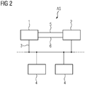
- FIG. 2 It gets on first Figure 2 referenced, in which a known redundant automation system is shown.
- This has a first and a second subsystem 1, 2, which are connected to peripheral units 4 via a field bus 3.
- Fieldbus 3 complies with the PROFIBUS-DP specification, for example. In principle, other bus systems, e.g. B. Ethernet (ProfiNet system redundancy), Modbus or also parallel bus systems are suitable.
- the peripheral units 4 receive signals from measuring transducers or measured value transmitters via input lines, which are used to detect a process status, and output signals to actuators via output lines with which the process is influenced.
- the process as well as the measuring transducers, measuring value transmitters and actuators are not shown in the figure for the sake of clarity.
- the two subsystems 1, 2 process the same control program, with one of the subsystems 1, 2 taking over the master function and the other subsystem 1, 2 the reserve function, with only the subsystem 1, 2 reading and / or writing accesses the peripheral units that exercise the master function or act as a master.
- the subsystem 1, 2 functioning as a master fails, the other subsystem 1, 2 takes over the master function.
- they In order to enable both subsystems 1, 2 to process their respective control programs or program paths of these control programs synchronously, they synchronize via two synchronization connections 5, 6, the redundancy and monitoring functions being implemented via these two synchronization connections 5, 6.
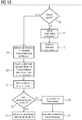
- process inputs of a process image of the master 1 are initially compared with process inputs of a process image of the reserve 2, and in a further operation 9 the communication of the reserve 2 with other components of the automation system AS, not shown here, is set.
- the reserve 2 also does not transmit any process output signals to the peripheral units 4.
- the reserve 2 does not start the troubleshooting operation until after a specified period of time or time delay Ts (decision or branch 10).
- This time delay Ts which can be configured by means of an engineering system of the automation system AS, is selected so that the reserve 2 can still safely take over the process control before a possible defect or failure of the master 1 (operation 11). In this case, the reserve 2 does not activate or even start the troubleshooting mode. It is pointed out that a defect or defect state is understood to mean a disturbed operation of a faulty subsystem, within the framework of which this subsystem cannot manage the process control.
- the reserve 2 starts the troubleshooting mode (step or operation 12).
- the reserve 2 detects that it is faulty (branch 13), which means that the reserve 2 is responsible for the loss of synchronization, the reserve 2 switches to a "defective" state (operation 14), with the Master continues process control (operation 15).
- the reserve 2 shows this defect status to a service technician by means of suitable display means.
- the defect status shows the service technician which CPU (CPU assembly, CPU module) needs to be replaced.
- the reserve 2 is "updated” by the master 1 in an operation 19 after the debugging operation, whereby the reserve 2 has all the relevant process control data of the master 1 takes over. This makes it possible to transfer the automation system AS from solo operation to redundancy operation at a later point in time at which both the master 1 and the reserve 2 have each ended the troubleshooting operation.
- the reserve 2 takes over the master role or process control (operation 20) as the "new" master and the master 1 acts as a "new" reserve, which starts another troubleshooting operation in an operation 21 in order to detect it whether the "new" reserve - ie the "old” master 1 - is faulty.
- the "new" reserve (“old” master 1) has not detected an error
- the "new" reserve changes to a defect state (operation 23) and the "new" master (“old” reserve 2) takes over process control in a solo operation.
Description
Die Erfindung betrifft ein Verfahren zum Betreiben eines redundanten, mit zwei Teilsystemen versehenen Automatisierungssystems, wobei in einem redundanten Betrieb eines der Teilsysteme als Master fungiert und die Prozesssteuerung übernimmt und das andere Teilsystem als Reserve fungiert.The invention relates to a method for operating a redundant automation system provided with two subsystems, one of the subsystems functioning as a master in redundant operation and taking over the process control and the other subsystem acting as a reserve.
Ein derartiges Verfahren ist beispielsweise aus der
Aus der
Der Erfindung liegt daher die Aufgabe zugrunde, ein Verfahren zum Betreiben eines Automatisierungssystems gemäß dem Oberbegriff des Anspruchs 1 anzugeben, welches die Verfügbarkeit des Automatisierungssystems erhöht.The invention is therefore based on the object of a method for operating an automation system according to the preamble of
Diese Aufgabe wird durch die im kennzeichnenden Teil des Anspruchs 1 angegebenen Maßnahmen gelöst.This object is achieved by the measures specified in the characterizing part of
Vorteilhaft ist, dass unabhängig davon, ob transiente Fehler auf dem als Master oder auf dem als Reserve fungierenden Teilsystem auftreten, ein Totalausfall des Automatisierungssystems weitgehend vermieden wird.It is advantageous that regardless of whether transient errors occur on the subsystem functioning as a master or on the subsystem functioning as a reserve, a total failure of the automation system is largely avoided.
Die Erfindung geht von der Idee aus, nicht unmittelbar nach einem Synchronisationsverlust - sondern erst zeitverzögert - einen Fehlersuchbetrieb in dem als Reserve fungierenden Teilsystem zu starten, um die Ursache eines Synchronisationsverlusts bzw. den potentiellen Fehler auf der Reserve zu ermitteln. Dadurch wird weitgehend vermieden, dass für den Fall, dass der Master aufgrund eines transienten Fehlers ausfällt, die Reserve sich bereits im Fehlersuchbetrieb befindet und dadurch während des Fehlersuchbetriebs das Automatisierungssystem komplett ausfällt. Die Zeitverzögerung bzw. die Zeitspanne ist so gewählt, dass für den Fall, dass der Master während dieser Zeitspanne ausfällt, die Reserve die Prozesssteuerung übernehmen kann, wobei in diesem Fall, die Reserve den Fehlersuchbetrieb erst gar nicht aktiviert bzw. startet. Unter einem kompletten Ausfall des Automatisierungssystems wird verstanden, dass weder der Master noch die Reserve in der Lage ist, die Prozesssteuerung zu übernehmen.The invention is based on the idea of not starting an error search mode immediately after a loss of synchronization, but rather with a time delay, in the subsystem functioning as a reserve in order to determine the cause of a loss of synchronization or the potential error in the reserve. In this way, it is largely avoided that in the event that the master fails due to a transient error, the reserve is already in troubleshooting mode and the automation system therefore fails completely during troubleshooting. The time delay or the time span is selected so that in the event that the master fails during this time span, the reserve can take over the process control, in which case the reserve does not even activate or start the troubleshooting mode. A complete failure of the automation system is understood to mean that neither the master nor the reserve is able to take over process control.
Nach dem Fehlersuchbetrieb der Reserve der Master diese Reserve im Rahmen eines Aufdatens mit relevanten (Steuerungs)Daten versorgt, wobei nach dem Aufdaten die Reserve als neuer Master die Prozesssteuerung übernimmt und der Master als neue Reserve einen weiteren Fehlersuchbetrieb startet. Dadurch wird geprüft, ob der "alte" Master ("neue" Reserve) für die Ursache des Synchronisationsverlustes bzw. für den Fehler verantwortlich ist, wobei der "neue" Master ("alte" Reserve) die Prozesssteuerung in einem Solobetrieb mit relevanten Steuerungs- bzw. Prozessdaten übernimmt.After troubleshooting the reserve, the master supplies this reserve with relevant (control) data as part of an update, with the reserve taking over the process control as the new master after the update and the master starting another troubleshooting operation as a new reserve. This checks whether the "old" master ("new" reserve) is responsible for the cause of the loss of synchronization or for the error, with the "new" master ("old" reserve) taking over the process control in a solo operation with relevant control or process data.
In einer Ausgestaltung der Erfindung gemäß den im Anspruch 2 angegebenen Maßnahmen ist vorgesehen, dass nach der vorgegebenen Zeitspanne (Timeout) und für den Fall, dass während des Fehlersuchbetriebs die Reserve einen Fehler detektiert, die Reserve einen Defekt-Zustand einnimmt. Der Master steuert immer noch in einem Solobetrieb den Prozess und es wird ermöglicht, dass ein Service-Techniker die Reserve austauschen kann. Unter einem Defekt-Zustand der Reserve wird ein gestörter Betrieb der Reserve verstanden, im Rahmen dessen die Reserve die Prozesssteuerung nicht bewerkstelligen kann.In one embodiment of the invention according to the measures specified in
In einer weiteren Ausgestaltung der Erfindung gemäß den im Anspruch 3 angegebenen Maßnahmen ist vorgesehen, dass für den Fall, dass während des Fehlersuchbetriebs der Master ausfällt bzw. gestört ist und daher der Master die Masterschaft bzw. die Prozesssteuerung nicht verwirklichen bzw. fortführen kann, der Master zunächst interne Master-Daten der Reserve übermittelt und einen Defekt-Zustand anzeigt, wobei die Reserve als neuer Master die Prozesssteuerung übernimmt. Diese Umschaltung bzw. dieser Masterschafts-Wechsel erfolgt zwar nicht "stoßfrei" (sondern es erfolgt aufgrund der Umschaltung ein Sprung bzw. Stoß der Werte an den Prozessausgängen), es wird allerdings auch in diesem Fall vermieden, dass das Automatisierungssystem ausfällt.In a further embodiment of the invention according to the measures specified in claim 3, it is provided that in the event that the master fails or is disturbed during the troubleshooting operation and therefore the master cannot realize or continue the masterhood or process control, the Master initially transmits internal master data from the reserve and indicates a defect state, with the reserve taking over process control as the new master. This switchover or this change of master class does not take place "bumplessly" (rather, there is a jump or jolt in the values at the process outputs due to the switchover), but in this case too, the automation system is prevented from failing.
Weitere vorteilhafte Ausgestaltungen der Erfindung ergeben sich aus den weiteren Unteransprüchen.Further advantageous refinements of the invention emerge from the further subclaims.
Anhand der Zeichnung, in der ein Ausführungsbeispiel der Erfindung veranschaulicht ist, werden im Folgenden die Erfindung, deren Ausgestaltungen sowie Vorteile näher erläutert.With the aid of the drawing, in which an exemplary embodiment of the invention is illustrated, the invention, its configurations and advantages are explained in more detail below.
Es zeigen:
Figur 1- ein Flussdiagramm und
Figur 2- ein redundantes Automatisierungssystem.
- Figure 1
- a flow chart and
- Figure 2
- a redundant automation system.
Die in den
Es wird zunächst auf
Es kann nun vorkommen, dass während des redundanten Betriebs des Automatisierungssystems AS beispielsweise aufgrund eines nicht rechtzeitig erkannten Speicherfehlers ein Synchronisationsverlust erkannt wird und daher das Automatisierungssystem AS von dem Redundanzbetrieb in einen Solobetrieb überführt wird, wobei ferner im Rahmen eines Fehlersuchbetriebs das Teilsystem 1, 2 lokalisiert wird, auf welchem der Fehler liegt bzw. welches für den Synchronisationsverlust verantwortlich ist.It can now happen that during the redundant operation of the automation system AS, for example, a loss of synchronization is recognized due to a memory error that was not recognized in good time, and the automation system AS is therefore transferred from redundant operation to solo operation, with the
Im Folgenden wird auf
Im Rahmen einer ersten Operation 8 werden zunächst Prozesseingänge eines Prozessabbildes des Masters 1 mit Prozesseingängen eines Prozessabbildes der Reserve 2 abgeglichen und in einer weiteren Operation 9 die Kommunikation der Reserve 2 mit weiteren hier nicht dargestellten Komponenten des Automatisierungssystems AS eingestellt. Im Rahmen der Operation 9 übermittelt ferner die Reserve 2 den Peripherieeinheiten 4 keine Prozessausgangssignale. Um zu verhindern, dass während eines Fehlersuchbetriebs der Reserve 2 das Automatisierungssystem AS komplett ausfällt, weil der Master 1 fehlerbehaftet ist, startet die Reserve 2 den Fehlersuchbetrieb erst nach einer vorgegebenen Zeitspanne bzw. Zeitverzögerung Ts (Entscheidung bzw. Verzweigung 10). Diese Zeitverzögerung Ts, welche mittels eines Engineering-Systems des Automatisierungssystems AS projektierbar ist, ist so gewählt, dass die Reserve 2 vor einem möglichen Defekt bzw. Ausfall des Masters 1 die Prozesssteuerung noch sicher übernehmen kann (Operation 11). In diesem Fall aktiviert bzw. startet die Reserve 2 den Fehlersuchbetrieb erst gar nicht. Es wird darauf hingewiesen, dass unter einem Defekt bzw. Defekt-Zustand ein gestörter Betrieb eines fehlerbehafteten Teilsystems verstanden wird, im Rahmen dessen dieses Teilsystem die Prozesssteuerung nicht bewerkstelligen kann.As part of a first operation 8, process inputs of a process image of the
Für den Fall, dass der Master 1 während dieser vorgegebenen Zeitspanne Ts nicht ausgefallen ist, startet die Reserve 2 den Fehlersuchbetrieb (Schritt bzw. Operation 12). Für den Fall, dass die Reserve 2 erkennt, dass sie fehlerbehaftet ist (Verzweigung 13), was bedeutet, dass die Reserve 2 für den Synchronisationsverlust verantwortlich ist, schaltet sich die Reserve 2 in einen Zustand "defekt" (Operation 14), wobei der Master die Prozesssteuerung fortsetzt (Operation 15). Die Reserve 2 zeigt mittels geeigneter Anzeigemittel einem Service-Techniker diesen Defektzustand an. Der Defektzustand zeigt dem Service-Techniker somit an, welche CPU (CPU-Baugruppe, CPU-Modul) ersetzt werden muss.In the event that the
Es kann vorkommen, dass während des Fehlersuchbetriebs der Reserve 2 der Master 1 im Hinblick auf die Prozesssteuerung ausfällt (Verzweigung 16). In diesem Fall übernimmt die Reserve 2 in einem Schritt 17 die internen Master-Daten (Werte eine Timers, Werte eines Zählers, Inhalte von Datenbausteinen, ...) und übernimmt anschließend die Prozesssteuerung, wobei der Wechsel nicht "stoßfrei" erfolgt (Operation 18). Ein Service-Techniker kann den gestörten Master 1 durch eine neue CPU (CPU-Baugruppe, CPU-Modul) ersetzen.It can happen that during the troubleshooting operation of
Für den Fall dagegen, dass während des Fehlersuchbetriebs der Reserve 2 der Master 1 nicht gestört ist (Verzweigung 16) wird nach dem Fehlersuchbetrieb in einer Operation 19 die Reserve 2 durch den Master 1 "aufgedated", wodurch die Reserve 2 alle relevanten Prozesssteuerdaten des Masters 1 übernimmt. Dadurch wird ermöglicht, zu einem späteren Zeitpunkt, zu dem sowohl der Master 1 als auch die Reserve 2 jeweils den Fehlersuchbetrieb beendet haben, das Automatisierungssystem AS von dem Solobetrieb in den Redundanzbetrieb zu überführen. Nach dem Aufdaten der Reserve 2 übernimmt die Reserve 2 als "neuer" Master die Masterschaft bzw. die Prozesssteuerung (Operation 20) und der Master 1 fungiert als "neue" Reserve, die in einer Operation 21 einen weiteren Fehlersuchbetrieb startet, um somit zu erkennen, ob die "neue" Reserve - also der "alte" Master 1 - fehlerbehaftet ist. Für den Fall, dass die "neue" Reserve ("alter" Master 1) keinen Fehler detektiert hat, wird die "neue" Reserve ("alter" Master 1) mit den relevanten Prozesssteuerdaten des "neuen" Masters ("alte" Reserve 2) "aufgedated" und das Automatisierungssystem AS wechselt wieder von einem Solobetrieb in den redundanten Betrieb (Operation 25). Für den Fall dagegen, dass die "neue" Reserve einen Fehler detektiert hat, wechselt die "neue" Reserve in einen Defektzustand (Operation 23) und der "neue" Master ("alte" Reserve 2) übernimmt in einem Solobetrieb die Prozesssteuerung. If, however, the
Claims (6)
- Method for operating a redundant automation system (AS) having two subsystems (1, 2), wherein in redundant operation one of the subsystems (1) operates as a master and assumes process control and the other subsystem (2) operates as a reserve, wherein the master (1) and the reserve (2) are synchronised by way of means of communication and in the event of a loss of synchronisation,a. Process inputs of a process image of the master (1) are compared with process inputs of a process image of the reserve (2),b. The communication of the reserve (2) with additional components of the automation system (AS) is adjusted,c. If the master (1) fails during a predefined period of time (Ts), the reserve (2) assumes process control as the new master,
characterised in thatd. In the event that the master (1) does not fail during the predefined period of time (Ts), after this period of time (Ts) the reserve (2) initiates troubleshooting to determine the cause of the loss of synchronisation, wherein if the reserve is not faulty, after troubleshooting the master (1) provides the reserve (2) with relevant process control data in the context of an update, wherein after updating the reserve (2) assumes process control as the new master and the master (1) initiates further troubleshooting as the new reserve. - Method according to claim 1, characterised in that if the reserve (2) detects an error during troubleshooting, the reserve (2) adopts a defective status.
- Method according to claim 1, characterised in that if the master (1) is interrupted during troubleshooting, the master (1) transfers internal master data to the reserve (2) and displays a defective status, wherein the reserve (2) assumes process control as the new master.
- Method according to one of the claims 1 to 3, characterised in that the predefined period of time (Ts) is configurable by means of an engineering system.
- Redundant automation system (AS) having two subsystems (1, 2), wherein in redundant operation one of the subsystems (1) operates as the master and assumes process control and the other subsystem (2) operates as the reserve, characterised in that the master (1) and the reserve (2) are defined and configured to perform the method according to one of the claims 1 to 4.
- Redundant automation system (AS) according to claim 5, characterised in that the predefined period of time (Ts) is configurable by means of an engineering system of the automation system (AS).
Priority Applications (3)
| Application Number | Priority Date | Filing Date | Title |
|---|---|---|---|
| EP16169894.9A EP3246771B1 (en) | 2016-05-17 | 2016-05-17 | Method for operating a redundant automation system |
| CN201710345783.0A CN107390511B (en) | 2016-05-17 | 2017-05-16 | Method for operating redundant automation systems |
| US15/596,269 US11262745B2 (en) | 2016-05-17 | 2017-05-16 | Method for operating a redundant automation system to increase availability of the automation system |
Applications Claiming Priority (1)
| Application Number | Priority Date | Filing Date | Title |
|---|---|---|---|
| EP16169894.9A EP3246771B1 (en) | 2016-05-17 | 2016-05-17 | Method for operating a redundant automation system |
Publications (2)
| Publication Number | Publication Date |
|---|---|
| EP3246771A1 EP3246771A1 (en) | 2017-11-22 |
| EP3246771B1 true EP3246771B1 (en) | 2021-06-30 |
Family
ID=56014859
Family Applications (1)
| Application Number | Title | Priority Date | Filing Date |
|---|---|---|---|
| EP16169894.9A Active EP3246771B1 (en) | 2016-05-17 | 2016-05-17 | Method for operating a redundant automation system |
Country Status (3)
| Country | Link |
|---|---|
| US (1) | US11262745B2 (en) |
| EP (1) | EP3246771B1 (en) |
| CN (1) | CN107390511B (en) |
Families Citing this family (17)
| Publication number | Priority date | Publication date | Assignee | Title |
|---|---|---|---|---|
| US11410129B2 (en) | 2010-05-01 | 2022-08-09 | Monday.com Ltd. | Digital processing systems and methods for two-way syncing with third party applications in collaborative work systems |
| WO2021161104A1 (en) | 2020-02-12 | 2021-08-19 | Monday.Com | Enhanced display features in collaborative network systems, methods, and devices |
| EP3547618B1 (en) * | 2018-03-29 | 2023-03-01 | Siemens Aktiengesellschaft | Method for establishing a redundant communication connection and fail-safe control unit |
| US11436359B2 (en) | 2018-07-04 | 2022-09-06 | Monday.com Ltd. | System and method for managing permissions of users for a single data type column-oriented data structure |
| US11698890B2 (en) | 2018-07-04 | 2023-07-11 | Monday.com Ltd. | System and method for generating a column-oriented data structure repository for columns of single data types |
| CN111142368B (en) * | 2019-09-02 | 2023-08-04 | 浙江中控技术股份有限公司 | Batch controller failure protection method |
| EP4062313A1 (en) | 2019-11-18 | 2022-09-28 | Monday.com Ltd. | Collaborative networking systems, methods, and devices |
| US11507738B2 (en) | 2019-11-18 | 2022-11-22 | Monday.Com | Digital processing systems and methods for automatic updates in collaborative work systems |
| IL297858A (en) | 2020-05-01 | 2023-01-01 | Monday Com Ltd | Digital processing systems and methods for enhanced collaborative workflow and networking systems, methods, and devices |
| US11829953B1 (en) | 2020-05-01 | 2023-11-28 | Monday.com Ltd. | Digital processing systems and methods for managing sprints using linked electronic boards |
| US11277361B2 (en) | 2020-05-03 | 2022-03-15 | Monday.com Ltd. | Digital processing systems and methods for variable hang-time for social layer messages in collaborative work systems |
| EP3936949A1 (en) * | 2020-07-09 | 2022-01-12 | Siemens Aktiengesellschaft | Redundant automation system and method for operating a redundant automation system |
| US11449668B2 (en) | 2021-01-14 | 2022-09-20 | Monday.com Ltd. | Digital processing systems and methods for embedding a functioning application in a word processing document in collaborative work systems |
| WO2023174550A1 (en) * | 2022-03-18 | 2023-09-21 | Telefonaktiebolaget Lm Ericsson (Publ) | Methods, computing nodes and system for controlling a physical entity |
| US11741071B1 (en) | 2022-12-28 | 2023-08-29 | Monday.com Ltd. | Digital processing systems and methods for navigating and viewing displayed content |
| US11886683B1 (en) | 2022-12-30 | 2024-01-30 | Monday.com Ltd | Digital processing systems and methods for presenting board graphics |
| US11893381B1 (en) | 2023-02-21 | 2024-02-06 | Monday.com Ltd | Digital processing systems and methods for reducing file bundle sizes |
Family Cites Families (10)
| Publication number | Priority date | Publication date | Assignee | Title |
|---|---|---|---|---|
| US5099153A (en) * | 1990-08-13 | 1992-03-24 | Dallas Semiconductor Corporation | Frequency-independent monitor circuit |
| US5777874A (en) * | 1996-02-12 | 1998-07-07 | Allen-Bradley Company, Inc. | Programmable controller backup system |
| DE19625195A1 (en) | 1996-06-24 | 1998-01-02 | Siemens Ag | Synchronization method |
| US7707619B2 (en) * | 2005-01-28 | 2010-04-27 | Microsoft Corporation | Method and system for troubleshooting when a program is adversely impacted by a security policy |
| US7617412B2 (en) * | 2006-10-25 | 2009-11-10 | Rockwell Automation Technologies, Inc. | Safety timer crosscheck diagnostic in a dual-CPU safety system |
| CN100492223C (en) * | 2007-03-30 | 2009-05-27 | 哈尔滨工程大学 | Switch circuit for engine redundant electrically-controlled system |
| CN103107904A (en) * | 2011-11-15 | 2013-05-15 | 北京南车时代信息技术有限公司 | Double-computer switching method of application server of ATS system control center |
| EP2765464A1 (en) * | 2013-02-08 | 2014-08-13 | Siemens Aktiengesellschaft | Method for operating a redundant automation system |
| EP2857913B1 (en) * | 2013-10-01 | 2019-04-24 | Siemens Aktiengesellschaft | Redundant automation system |
| CN103955188B (en) * | 2014-04-24 | 2017-02-15 | 清华大学 | Control system and method supporting redundancy switching function |
-
2016
- 2016-05-17 EP EP16169894.9A patent/EP3246771B1/en active Active
-
2017
- 2017-05-16 CN CN201710345783.0A patent/CN107390511B/en active Active
- 2017-05-16 US US15/596,269 patent/US11262745B2/en active Active
Also Published As
| Publication number | Publication date |
|---|---|
| US20170351252A1 (en) | 2017-12-07 |
| CN107390511B (en) | 2021-12-07 |
| CN107390511A (en) | 2017-11-24 |
| US11262745B2 (en) | 2022-03-01 |
| EP3246771A1 (en) | 2017-11-22 |
Similar Documents
| Publication | Publication Date | Title |
|---|---|---|
| EP3246771B1 (en) | Method for operating a redundant automation system | |
| WO2013124268A1 (en) | Method for the failsafe operation of a process control system with redundant control devices | |
| EP2667269B1 (en) | Method for operating a redundant automation system | |
| EP1743225A1 (en) | Redundant computerizing system comprising a master programmable automaton and a standby programmable automaton | |
| DE102012000158A1 (en) | Adaptive multi-redundant annular network and method for selecting a detour | |
| EP3214512B1 (en) | Redundant control system for an actuator and method for its redundant control | |
| DE19842593C2 (en) | Method for operating a bus master on a fieldbus | |
| EP2418580B1 (en) | Method for operating a network and network | |
| EP0624843A2 (en) | Method for detecting addressing error for an electrical device | |
| WO2014161986A1 (en) | Control and data transfer system for redundant process control and method for firmware updating | |
| DE102010041437B4 (en) | Checking functions of a control system with components | |
| EP3457232B1 (en) | Method for operating a highly available automation system | |
| EP2048555A1 (en) | Analogue output device with error recognition | |
| EP3200033B1 (en) | Assembly comprising at least two peripheral units with a sensor | |
| EP3821310B1 (en) | Method for compensating for an error function of a field device in an automation technology system | |
| EP1692578B1 (en) | Peripheral unit for a redundant control system | |
| DE102020200141A1 (en) | Fault tolerant rule system | |
| AT12998U1 (en) | REDUNDANT CONTROL SYSTEM AND CONTROLLER AND PERIPHERAL UNIT | |
| EP3654121B1 (en) | Redundant automation system with a plurality of processing units for each hardware unit | |
| EP4133343B1 (en) | Redundant automation system and method for operating a redundant automation system | |
| EP3229141A1 (en) | Method for improving availability of a redundant automation system and redundant automation system | |
| EP0299375B1 (en) | Method for connecting a computer in a multicomputer system | |
| EP1729433B1 (en) | Method for correcting propagation delay in a communications structure | |
| EP1262872B1 (en) | Master-CPU and Reserve-CPU synchronisation interface | |
| DE10329196A1 (en) | Reset method for a vehicle electronic control unit in which the unit is monitored by a central control unit and when a fault condition is detected it is reset by a reset command being applied to a reset trigger unit |
Legal Events
| Date | Code | Title | Description |
|---|---|---|---|
| PUAI | Public reference made under article 153(3) epc to a published international application that has entered the european phase |
Free format text: ORIGINAL CODE: 0009012 |
|
| STAA | Information on the status of an ep patent application or granted ep patent |
Free format text: STATUS: THE APPLICATION HAS BEEN PUBLISHED |
|
| AK | Designated contracting states |
Kind code of ref document: A1 Designated state(s): AL AT BE BG CH CY CZ DE DK EE ES FI FR GB GR HR HU IE IS IT LI LT LU LV MC MK MT NL NO PL PT RO RS SE SI SK SM TR |
|
| AX | Request for extension of the european patent |
Extension state: BA ME |
|
| STAA | Information on the status of an ep patent application or granted ep patent |
Free format text: STATUS: REQUEST FOR EXAMINATION WAS MADE |
|
| 17P | Request for examination filed |
Effective date: 20180504 |
|
| RBV | Designated contracting states (corrected) |
Designated state(s): AL AT BE BG CH CY CZ DE DK EE ES FI FR GB GR HR HU IE IS IT LI LT LU LV MC MK MT NL NO PL PT RO RS SE SI SK SM TR |
|
| GRAP | Despatch of communication of intention to grant a patent |
Free format text: ORIGINAL CODE: EPIDOSNIGR1 |
|
| STAA | Information on the status of an ep patent application or granted ep patent |
Free format text: STATUS: GRANT OF PATENT IS INTENDED |
|
| RIC1 | Information provided on ipc code assigned before grant |
Ipc: G05B 19/042 20060101AFI20210223BHEP |
|
| GRAS | Grant fee paid |
Free format text: ORIGINAL CODE: EPIDOSNIGR3 |
|
| INTG | Intention to grant announced |
Effective date: 20210322 |
|
| GRAA | (expected) grant |
Free format text: ORIGINAL CODE: 0009210 |
|
| STAA | Information on the status of an ep patent application or granted ep patent |
Free format text: STATUS: THE PATENT HAS BEEN GRANTED |
|
| AK | Designated contracting states |
Kind code of ref document: B1 Designated state(s): AL AT BE BG CH CY CZ DE DK EE ES FI FR GB GR HR HU IE IS IT LI LT LU LV MC MK MT NL NO PL PT RO RS SE SI SK SM TR |
|
| REG | Reference to a national code |
Ref country code: CH Ref legal event code: EP |
|
| REG | Reference to a national code |
Ref country code: AT Ref legal event code: REF Ref document number: 1406915 Country of ref document: AT Kind code of ref document: T Effective date: 20210715 |
|
| REG | Reference to a national code |
Ref country code: DE Ref legal event code: R096 Ref document number: 502016013296 Country of ref document: DE |
|
| REG | Reference to a national code |
Ref country code: IE Ref legal event code: FG4D Free format text: LANGUAGE OF EP DOCUMENT: GERMAN |
|
| REG | Reference to a national code |
Ref country code: LT Ref legal event code: MG9D |
|
| PG25 | Lapsed in a contracting state [announced via postgrant information from national office to epo] |
Ref country code: HR Free format text: LAPSE BECAUSE OF FAILURE TO SUBMIT A TRANSLATION OF THE DESCRIPTION OR TO PAY THE FEE WITHIN THE PRESCRIBED TIME-LIMIT Effective date: 20210630 Ref country code: BG Free format text: LAPSE BECAUSE OF FAILURE TO SUBMIT A TRANSLATION OF THE DESCRIPTION OR TO PAY THE FEE WITHIN THE PRESCRIBED TIME-LIMIT Effective date: 20210930 Ref country code: FI Free format text: LAPSE BECAUSE OF FAILURE TO SUBMIT A TRANSLATION OF THE DESCRIPTION OR TO PAY THE FEE WITHIN THE PRESCRIBED TIME-LIMIT Effective date: 20210630 |
|
| REG | Reference to a national code |
Ref country code: NL Ref legal event code: MP Effective date: 20210630 |
|
| PG25 | Lapsed in a contracting state [announced via postgrant information from national office to epo] |
Ref country code: LV Free format text: LAPSE BECAUSE OF FAILURE TO SUBMIT A TRANSLATION OF THE DESCRIPTION OR TO PAY THE FEE WITHIN THE PRESCRIBED TIME-LIMIT Effective date: 20210630 Ref country code: GR Free format text: LAPSE BECAUSE OF FAILURE TO SUBMIT A TRANSLATION OF THE DESCRIPTION OR TO PAY THE FEE WITHIN THE PRESCRIBED TIME-LIMIT Effective date: 20211001 Ref country code: NO Free format text: LAPSE BECAUSE OF FAILURE TO SUBMIT A TRANSLATION OF THE DESCRIPTION OR TO PAY THE FEE WITHIN THE PRESCRIBED TIME-LIMIT Effective date: 20210930 Ref country code: RS Free format text: LAPSE BECAUSE OF FAILURE TO SUBMIT A TRANSLATION OF THE DESCRIPTION OR TO PAY THE FEE WITHIN THE PRESCRIBED TIME-LIMIT Effective date: 20210630 Ref country code: SE Free format text: LAPSE BECAUSE OF FAILURE TO SUBMIT A TRANSLATION OF THE DESCRIPTION OR TO PAY THE FEE WITHIN THE PRESCRIBED TIME-LIMIT Effective date: 20210630 |
|
| PG25 | Lapsed in a contracting state [announced via postgrant information from national office to epo] |
Ref country code: SM Free format text: LAPSE BECAUSE OF FAILURE TO SUBMIT A TRANSLATION OF THE DESCRIPTION OR TO PAY THE FEE WITHIN THE PRESCRIBED TIME-LIMIT Effective date: 20210630 Ref country code: SK Free format text: LAPSE BECAUSE OF FAILURE TO SUBMIT A TRANSLATION OF THE DESCRIPTION OR TO PAY THE FEE WITHIN THE PRESCRIBED TIME-LIMIT Effective date: 20210630 Ref country code: EE Free format text: LAPSE BECAUSE OF FAILURE TO SUBMIT A TRANSLATION OF THE DESCRIPTION OR TO PAY THE FEE WITHIN THE PRESCRIBED TIME-LIMIT Effective date: 20210630 Ref country code: CZ Free format text: LAPSE BECAUSE OF FAILURE TO SUBMIT A TRANSLATION OF THE DESCRIPTION OR TO PAY THE FEE WITHIN THE PRESCRIBED TIME-LIMIT Effective date: 20210630 Ref country code: RO Free format text: LAPSE BECAUSE OF FAILURE TO SUBMIT A TRANSLATION OF THE DESCRIPTION OR TO PAY THE FEE WITHIN THE PRESCRIBED TIME-LIMIT Effective date: 20210630 Ref country code: NL Free format text: LAPSE BECAUSE OF FAILURE TO SUBMIT A TRANSLATION OF THE DESCRIPTION OR TO PAY THE FEE WITHIN THE PRESCRIBED TIME-LIMIT Effective date: 20210630 Ref country code: PT Free format text: LAPSE BECAUSE OF FAILURE TO SUBMIT A TRANSLATION OF THE DESCRIPTION OR TO PAY THE FEE WITHIN THE PRESCRIBED TIME-LIMIT Effective date: 20211102 Ref country code: ES Free format text: LAPSE BECAUSE OF FAILURE TO SUBMIT A TRANSLATION OF THE DESCRIPTION OR TO PAY THE FEE WITHIN THE PRESCRIBED TIME-LIMIT Effective date: 20210630 |
|
| PG25 | Lapsed in a contracting state [announced via postgrant information from national office to epo] |
Ref country code: PL Free format text: LAPSE BECAUSE OF FAILURE TO SUBMIT A TRANSLATION OF THE DESCRIPTION OR TO PAY THE FEE WITHIN THE PRESCRIBED TIME-LIMIT Effective date: 20210630 |
|
| REG | Reference to a national code |
Ref country code: DE Ref legal event code: R097 Ref document number: 502016013296 Country of ref document: DE |
|
| PG25 | Lapsed in a contracting state [announced via postgrant information from national office to epo] |
Ref country code: DK Free format text: LAPSE BECAUSE OF FAILURE TO SUBMIT A TRANSLATION OF THE DESCRIPTION OR TO PAY THE FEE WITHIN THE PRESCRIBED TIME-LIMIT Effective date: 20210630 |
|
| PLBE | No opposition filed within time limit |
Free format text: ORIGINAL CODE: 0009261 |
|
| STAA | Information on the status of an ep patent application or granted ep patent |
Free format text: STATUS: NO OPPOSITION FILED WITHIN TIME LIMIT |
|
| PG25 | Lapsed in a contracting state [announced via postgrant information from national office to epo] |
Ref country code: AL Free format text: LAPSE BECAUSE OF FAILURE TO SUBMIT A TRANSLATION OF THE DESCRIPTION OR TO PAY THE FEE WITHIN THE PRESCRIBED TIME-LIMIT Effective date: 20210630 |
|
| 26N | No opposition filed |
Effective date: 20220331 |
|
| REG | Reference to a national code |
Ref country code: CH Ref legal event code: PL |
|
| REG | Reference to a national code |
Ref country code: BE Ref legal event code: MM Effective date: 20220531 |
|
| PG25 | Lapsed in a contracting state [announced via postgrant information from national office to epo] |
Ref country code: MC Free format text: LAPSE BECAUSE OF FAILURE TO SUBMIT A TRANSLATION OF THE DESCRIPTION OR TO PAY THE FEE WITHIN THE PRESCRIBED TIME-LIMIT Effective date: 20210630 Ref country code: LU Free format text: LAPSE BECAUSE OF NON-PAYMENT OF DUE FEES Effective date: 20220517 Ref country code: LI Free format text: LAPSE BECAUSE OF NON-PAYMENT OF DUE FEES Effective date: 20220531 Ref country code: CH Free format text: LAPSE BECAUSE OF NON-PAYMENT OF DUE FEES Effective date: 20220531 |
|
| PG25 | Lapsed in a contracting state [announced via postgrant information from national office to epo] |
Ref country code: LT Free format text: LAPSE BECAUSE OF FAILURE TO SUBMIT A TRANSLATION OF THE DESCRIPTION OR TO PAY THE FEE WITHIN THE PRESCRIBED TIME-LIMIT Effective date: 20210630 Ref country code: IE Free format text: LAPSE BECAUSE OF NON-PAYMENT OF DUE FEES Effective date: 20220517 |
|
| PG25 | Lapsed in a contracting state [announced via postgrant information from national office to epo] |
Ref country code: BE Free format text: LAPSE BECAUSE OF NON-PAYMENT OF DUE FEES Effective date: 20220531 |
|
| REG | Reference to a national code |
Ref country code: AT Ref legal event code: MM01 Ref document number: 1406915 Country of ref document: AT Kind code of ref document: T Effective date: 20220517 |
|
| PG25 | Lapsed in a contracting state [announced via postgrant information from national office to epo] |
Ref country code: AT Free format text: LAPSE BECAUSE OF NON-PAYMENT OF DUE FEES Effective date: 20220517 |
|
| PGFP | Annual fee paid to national office [announced via postgrant information from national office to epo] |
Ref country code: IT Payment date: 20230523 Year of fee payment: 8 Ref country code: FR Payment date: 20230515 Year of fee payment: 8 Ref country code: DE Payment date: 20220620 Year of fee payment: 8 |
|
| PGFP | Annual fee paid to national office [announced via postgrant information from national office to epo] |
Ref country code: GB Payment date: 20230605 Year of fee payment: 8 |
|
| PG25 | Lapsed in a contracting state [announced via postgrant information from national office to epo] |
Ref country code: HU Free format text: LAPSE BECAUSE OF FAILURE TO SUBMIT A TRANSLATION OF THE DESCRIPTION OR TO PAY THE FEE WITHIN THE PRESCRIBED TIME-LIMIT; INVALID AB INITIO Effective date: 20160517 |