EP2667269B1 - Method for operating a redundant automation system - Google Patents
Method for operating a redundant automation system Download PDFInfo
- Publication number
- EP2667269B1 EP2667269B1 EP12169553.0A EP12169553A EP2667269B1 EP 2667269 B1 EP2667269 B1 EP 2667269B1 EP 12169553 A EP12169553 A EP 12169553A EP 2667269 B1 EP2667269 B1 EP 2667269B1
- Authority
- EP
- European Patent Office
- Prior art keywords
- subsystem
- control program
- slave
- master
- time
- Prior art date
- Legal status (The legal status is an assumption and is not a legal conclusion. Google has not performed a legal analysis and makes no representation as to the accuracy of the status listed.)
- Active
Links
- 238000000034 method Methods 0.000 title claims description 64
- 238000012545 processing Methods 0.000 claims description 75
- 230000008569 process Effects 0.000 claims description 55
- 238000004886 process control Methods 0.000 claims description 14
- 238000012546 transfer Methods 0.000 claims description 8
- 230000002093 peripheral effect Effects 0.000 description 7
- 230000008859 change Effects 0.000 description 6
- 230000005540 biological transmission Effects 0.000 description 5
- 238000004891 communication Methods 0.000 description 5
- 230000006870 function Effects 0.000 description 5
- 230000008878 coupling Effects 0.000 description 4
- 238000010168 coupling process Methods 0.000 description 4
- 238000005859 coupling reaction Methods 0.000 description 4
- 230000001360 synchronised effect Effects 0.000 description 3
- 230000007704 transition Effects 0.000 description 3
- 238000013459 approach Methods 0.000 description 2
- 230000004044 response Effects 0.000 description 2
- 230000004913 activation Effects 0.000 description 1
- 230000008901 benefit Effects 0.000 description 1
- 238000006243 chemical reaction Methods 0.000 description 1
- 238000011161 development Methods 0.000 description 1
- 230000007246 mechanism Effects 0.000 description 1
- 238000003032 molecular docking Methods 0.000 description 1
- 238000012544 monitoring process Methods 0.000 description 1
- 230000008520 organization Effects 0.000 description 1
- 230000008439 repair process Effects 0.000 description 1
- 230000003068 static effect Effects 0.000 description 1
Images


Classifications
-
- G—PHYSICS
- G05—CONTROLLING; REGULATING
- G05B—CONTROL OR REGULATING SYSTEMS IN GENERAL; FUNCTIONAL ELEMENTS OF SUCH SYSTEMS; MONITORING OR TESTING ARRANGEMENTS FOR SUCH SYSTEMS OR ELEMENTS
- G05B9/00—Safety arrangements
- G05B9/02—Safety arrangements electric
- G05B9/03—Safety arrangements electric with multiple-channel loop, i.e. redundant control systems
-
- G—PHYSICS
- G06—COMPUTING; CALCULATING OR COUNTING
- G06F—ELECTRIC DIGITAL DATA PROCESSING
- G06F16/00—Information retrieval; Database structures therefor; File system structures therefor
- G06F16/20—Information retrieval; Database structures therefor; File system structures therefor of structured data, e.g. relational data
- G06F16/27—Replication, distribution or synchronisation of data between databases or within a distributed database system; Distributed database system architectures therefor
- G06F16/275—Synchronous replication
-
- G—PHYSICS
- G05—CONTROLLING; REGULATING
- G05B—CONTROL OR REGULATING SYSTEMS IN GENERAL; FUNCTIONAL ELEMENTS OF SUCH SYSTEMS; MONITORING OR TESTING ARRANGEMENTS FOR SUCH SYSTEMS OR ELEMENTS
- G05B19/00—Programme-control systems
- G05B19/02—Programme-control systems electric
- G05B19/04—Programme control other than numerical control, i.e. in sequence controllers or logic controllers
- G05B19/05—Programmable logic controllers, e.g. simulating logic interconnections of signals according to ladder diagrams or function charts
- G05B19/058—Safety, monitoring
Definitions
- the invention relates to a method for operating an automation system having at least two subsystems, which are each provided with a control program, wherein for transferring the process control of a single operation of one of the subsystems in a redundant control operation with another of the subsystems relevant data of one subsystem to the other subsystem be transmitted during an update phase of the automation system. Moreover, the invention relates to a redundant automation system which is suitable for carrying out the method.
- H systems In the automation environment, increasingly highly available solutions (H systems) are required, which are suitable for reducing any downtimes of the system to a minimum.
- H systems high availability solutions
- the development of such highly available solutions is very costly, with an H-system usually used in the automation environment being characterized in that two or more subsystems in the form of automation devices or computer systems are coupled to one another via a synchronization connection.
- both subsystems can read and / or write access to the peripheral units connected to this H system.
- One of the two subsystems is leading the periphery connected to the system. This means that outputs to peripheral units or output information for these peripheral units are performed only by one of the two subsystems, which works as a master or has taken over the master function. So that both subsystems can run synchronously, they are synchronized via the synchronization connection at regular intervals.
- different characteristics can be distinguished (warmstandby, hot-standby).
- an H-system requires a bumpless "failover" if one of the subsystems fails and must be switched to the other subsystem, whereby this other subsystem takes over the process control in a so-called solo or non-redundant operation.
- both subsystems must have the same system state at the time of failure. This is ensured by the appropriate synchronization method. If both subsystems process the input information (inputs) of the process, then both systems are in the same system state if they - with the same process input data or process input information - their respective "thread global" data (common data of programs, especially programs of different priorities ) change in the same way. To achieve this, the synchronization process ensures that the individual threads of the two subsystems are interrupted or processed in the same way. This results in an identical "thread mountains".
- the invention is therefore based on the object of specifying a method of the type mentioned, by means of which an updating is facilitated.
- a redundant automation system is to be created, which is suitable for carrying out the method.
- the subsystem operating in solo mode - hereinafter referred to as master - creates a copy of its relevant data representing the internal state of the master at the beginning of this updating phase, fragmented or "fragmented" switched subsystem - hereinafter referred to as slave or reserve - transferred.
- This internal state is essentially determined or specified by static and dynamic data, data blocks, process input and output values as well as configuration data.
- the slave is finally introduced via the shares step by step and temporally asynchronous to the current processing of the control program by the master to the internal state of the master, the slave begins with the processing of the shares only if it has received the copy completely.
- the slave cycles through the same program paths, which the master has already passed through, with the relevant data in accordance with the releases.
- a "lead-in” is the time difference between the start of the processing of the processing sections by the master and the beginning of the processing of the corresponding processing sections by the slave, which is the time of the occurrence of the release or the release signal corresponds, understood.
- a program is understood to mean both a program as such, as well as a subroutine, a part of a program, a task, a thread, an organization block, a function block or any other suitable program code for implementing an automation function
- Programs of an automation system are usually divided into priority classes and according to their assigned priority edited or executed.
- the Aufdat phase is completed and the automation system works from this point in one redundant mode.
- the master is transferred from the solo operation to a redundant operation with the slave or the reserve, whereby from this time the master and the slave due to an event, for example in the form of a process alarm, same program paths preferably time asynchronously through ,
- the automation system can also be designed such that, after the updating phase or after the updating, a temporally synchronous processing of the program paths is realized.
- the process input values are transmitted together with the shares to the other subsystem.
- the information relevant to the other subsystem is first summarized or collected and finally transmitted to the other subsystem. This reduces the "administrative burden" for both subsystems.
- FIG. 3 it is going on first FIG. 3 referenced, in which a known per se redundant, two subsystems comprehensive automation system is shown.
- a first subsystem Ta and a second subsystem Tb are connected to a peripheral unit Pe via a field bus Fb.
- the fieldbus Fb satisfies, for example, the PROFIBUS-DP specification.
- other bus systems eg. As Ethernet, Fieldbus, Modbus, ProfiNet IO or even parallel bus systems suitable.
- the peripheral unit Pe receives signals from transducers or transducers, which are used to detect a process status, via input lines Es and outputs signals to actuators via output lines As, which influence the process.
- the process and the transducers, transducers and actuators are not shown in the figure for clarity.
- the two Subsystems Ta, Tb work cyclically and synchronously on the same control program. For their synchronization, a synchronization connection Sv is provided, wherein the redundancy and monitoring functions are realized via this synchronization connection Sv
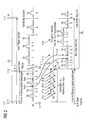
- FIG. 1 For explaining an event-synchronous processing of the control programs and for a better understanding of the invention, the following is on FIG. 1 referenced in which a in the earlier European patent application 12166006.2 proposed sequence of a time-asynchronous coupling of two subsystems is shown.
- An "event-synchronous processing" in this context means that both the master and the slave undergo the same program paths of the respective control program as a result of an event, whereby the runs take place in a time-asynchronous manner.
- a subsystem is operated as a master M and a subsystem as a slave S or as a reserve.
- the master M is therefore leading in terms of the control of a technical process and takes over the process control, wherein the master processes the process input information or process input values from the peripheral unit Pe (FIG. FIG. 3 ) reads and temporally asynchronously the slave S provides.
- the slave S takes over the master function or the master shaft only if the master M fails due to a fault.
- the master M processes a program P1 for controlling the technical process, wherein the slave S also processes a program P2 corresponding to this control program P1.
- Both control programs P1, P2 have a plurality of processing sections (Va) of different periods of time, wherein the control programs P1, P2 are interruptible at the respective start and the respective end of each processing section Va.
- the beginning and end of each processing section Va which usually includes a plurality of program codes, thus represent interruptible program locations 0, 1, 2,... Y.
- the respective control program P1, P2 can be interrupted at these points 0, 1, 2,... Y by means of the master M and the slave S in order to be able to initiate suitable reactions after the occurrence of an event or a process alarm.
- the respective control program P1, P2 can be interrupted at these interruption points 0, 1, 2,... Y, so that the master M and the slave S clear shares, acknowledgments or other information via the fieldbus Fb or via the synchronization connection Sv (FIG ) can exchange.
- a respective predeterminable or predetermined time interval Zi, i 1, 2,...
- a release or a release signal indicating the slave S up to which processing section Va the slave S may process the control program P2.
- These processing sections Va of the control program P2 correspond to those already processed by the master M during the processing of the control program P1.
- the master M transmits a release F1 to the slave S.
- This release F1 comprises the information for the slave S that this is to be processed control program P2 up to an interruption point P2_6 (interruption point 6), the interruption point P2_6 of the control program P2 corresponding to the interruption point P1_6 of the control program P1.
- the slave S can process the processing sections Va of the control program P2 which correspond to the processing sections Va of the control program P1 up to the time of generation of the release or the release signal, for the sake of simplicity being assumed in the example Time of generation of the release corresponds to the time of transmission of the release to the slave S.
- the processing of these processing steps Va by means of the slave S thus takes place asynchronously with respect to the processing of the corresponding processing sections Va by means of the master M, wherein after processing the processing sections Va of the control program P2 by the slave S processing of further processing sections Va by the slave S only then takes place when the master M transmits the slave S another release.
- the time of occurrence of this interruption point P1_6, P2_6 represents the beginning of a time interval Z2 following the time interval Z1.
- the further time-asynchronous processing of the control programs P1, P2 takes place.
- the master M transmits to the slave S a further release F2 which indicates to the slave S that he can process further processing sections Va up to the interruption point P2_A.
- These processing sections Va again correspond to those which the master M has already processed from the time t2 to the time t3, ie to the point of interruption P1_A.
- the slave S processes the processing sections Va from the time t2 of the previous release F1 to the time t3 of the current release F2.
- the time t3 at which the first interruption point P1_A has occurred after the expiration of the time interval Z2 is the beginning of a time interval Z3 following the time interval Z2.
- an event designates such an event to which the master M has to react suitably in accordance with the control program P1 during the time interval Z3 at a time t4.
- the master M does not transmit to the slave S a release F3 at a time of occurrence of an interruption point following the time interval Z3 after the time interval Z3, but at a time t5 of the occurrence of an interruption point P1_C following the occurrence of the event E (interruption point C).
- the time interval Z3 is shortened due to the event E, wherein the time t5 is the beginning of a subsequent time interval Z4.
- the slave S processes the processing sections Va of the control program P2 which correspond to the processing sections Va of the control program P1 which the master M has already processed between the times t3 and t5.
- the master M processes during the time interval Z4 processing sections Va higher priority, z. B.
- the master M performs a thread change at time t5, and in turn transmits after the expiration of the time interval Z4 at time t6 a release F4 at a time t7, at which a first on the time interval Z4 following interruption point P1_12 (point of interruption 12) occurs.
- the slave S also processes processing sections Va up to an interruption point P2_12 (interruption point 12) of the control program P2, these processing sections Va corresponding to the processing sections Va of the control program P1 between the times t5 and t7, and the slave S also executing a thread change.
- the enables of the master M enable the slave S to go through the same "thread mountains" as the master M, which means that the slave S has a "Thread change” takes place at a point in the control program P2, which corresponds to the position in the control program P1.
- the slave S continues its processing only if it is requested by the master M by means of a release.
- the master M processes these in real time as in a stand-alone or in a non-redundant mode and issues at regular intervals and after the occurrence of events releases for processing corresponding processing sections by the slave S, wherein the master M further processes its control program P1 and does not actively wait for a response from the slave S.
- the slave S runs with respect to the processing of the corresponding processing sections to the master M and processes them based on the granted master shares.
- This transition begins at a time t11, to which the master M has recognized that the slave S is connected to the fieldbus Fb (FIG. FIG. 3 ) is coupled, starting from this time t11 the Aufdat phase of both the master M and the slave S begins. From this point in time t11, the master M prepares a local copy K of all relevant data, which represents its internal state up to this point in time t11, wherein the master M continues to control the technical process in solo mode and processes processing sections Va of a control program P5.
- the slave S After this activation by the master M, the slave S approaches the internal state of the master Ms by the slave S processing the data of the copy K in accordance with the releases F13 to F16. At this time, the slave S processes the processing sections Va of its control program P6 which correspond to the processing sections Va of the control program P5 of the master M until the time t13, the slave S taking into account the process input values Ew3, Ew4 with respect to the processing of the control program P6.
- the slave S Due to the fact that the slave S approaches the internal state of the master M in terms of time asynchronously, the slave S travels to the master M with regard to the processing of the corresponding processing sections Va of the control program P6, this time lag being reduced to a tolerable level got to; too high a time lag can lead to a loss of redundancy.
- the processing speed of the slave S relative to the processing speed of the master M is higher, which is shown in FIG in the form of "shortened" shown processing sections Va is shown in the control program P6.
- This relative increase in the processing speed of the slave S can, for.
- the slave S processes the processing sections Va of its program P6 faster or the master M processes the processing sections Va of its program P5 more slowly.
- the Aufdat phase of the slaves S and thus of the automation system beginning at the time t12 is completed.
- the caster was reduced to a tolerable level at a time t15.
- This measure is chosen or specified such that in the event of a failure of the master M, the slave S can take over the master shaft bumplessly.
- the time difference between a time t16 and the time t15 represents the tolerable level, which in a practical embodiment of the invention is about 20 milliseconds.
- the slave S processes from the time t14 to the time t15 both the caches stored during the transmission of the copy K shares F13 to F16 and shares F17, F18, F19, which the master M the slave S. transmitted after this transmission.
- F17 to F19 indicate to the slave S which processing sections Va of the control program P6 are to be further processed by the slave S, these processing sections Va correspond to the processing sections Va of the control program P5 which the master M has already processed from the time t14.
- the slave S processes from the time t14 to the time t16 all released processing sections Va of its control program P6, which correspond to those which the master M has already processed from the time t11 to the time t15.
- the updating phase is completed and the automation system is converted into a redundant mode.
- the process control is the solo operation of the master M is the redundant operation with the slave S passed, the further runs of the corresponding program paths on the master M and the slave S in time from the time t16 in the manner described asynchronously or in a known manner can be synchronized in time.
Description
Die Erfindung betrifft ein Verfahren zum Betreiben eines mindestens zwei Teilsysteme aufweisenden Automatisierungssystems, die jeweils mit einem Steuerprogramm versehen sind, wobei zum Überführen der Prozesssteuerung von einem Solobetrieb eines der Teilsysteme in einen redundanten Steuerbetrieb mit einem anderen der Teilsysteme relevante Daten des einen Teilsystems dem anderen Teilsystem im Rahmen einer Aufdat-Phase des Automatisierungssystems übertragen werden. Darüber hinaus betrifft die Erfindung ein redundantes Automatisierungssystem, welches zur Durchführung des Verfahrens geeignet ist.The invention relates to a method for operating an automation system having at least two subsystems, which are each provided with a control program, wherein for transferring the process control of a single operation of one of the subsystems in a redundant control operation with another of the subsystems relevant data of one subsystem to the other subsystem be transmitted during an update phase of the automation system. Moreover, the invention relates to a redundant automation system which is suitable for carrying out the method.
Im Automatisierungsumfeld werden verstärkt hochverfügbare Lösungen (H-Systeme) gefordert, welche geeignet sind, eventuell auftretende Stillstandszeiten der Anlage auf ein Minimum zu reduzieren. Die Entwicklung derartiger hochverfügbarer Lösungen ist sehr kostenintensiv, wobei ein im Automatisierungsumfeld gewöhnlich eingesetztes H-System sich dadurch auszeichnet, dass zwei oder mehrere Teilsysteme in Form von Automatisierungsgeräten oder Rechnersystemen über eine Synchronisationsverbindung miteinander gekoppelt sind. Auf die an dieses H-System angeschlossenen Peripherieeinheiten können prinzipiell beide Teilsysteme lesend und/oder schreibend zugreifen. Eines der beiden Teilsysteme ist bezüglich der an das System angeschlossenen Peripherie führend. Dies bedeutet, dass Ausgaben zu Peripherieeinheiten bzw. Ausgangsinformationen für diese Peripherieeinheiten nur von einem der beiden Teilsysteme durchgeführt werden, welches als Master arbeitet bzw. die Masterfunktion übernommen hat. Damit beide Teilsysteme synchron ablaufen können, werden diese über die Synchronisationsverbindung in regelmäßigen Abständen synchronisiert. Bezüglich der Häufigkeit der Synchronisation und deren Umfang können verschiedene Ausprägungen unterschieden werden (warmstandby, hot-standby).In the automation environment, increasingly highly available solutions (H systems) are required, which are suitable for reducing any downtimes of the system to a minimum. The development of such highly available solutions is very costly, with an H-system usually used in the automation environment being characterized in that two or more subsystems in the form of automation devices or computer systems are coupled to one another via a synchronization connection. In principle, both subsystems can read and / or write access to the peripheral units connected to this H system. One of the two subsystems is leading the periphery connected to the system. This means that outputs to peripheral units or output information for these peripheral units are performed only by one of the two subsystems, which works as a master or has taken over the master function. So that both subsystems can run synchronously, they are synchronized via the synchronization connection at regular intervals. With regard to the frequency of the synchronization and its scope, different characteristics can be distinguished (warmstandby, hot-standby).
Häufig wird von einem H-System ein stoßfreies "Failover" gefordert, falls eines der Teilsysteme ausfällt und auf das andere Teilsystem umgeschaltet werden muss, wodurch dieses andere Teilsystem in einem so genannten Solobetrieb bzw. nicht-redundanten Betrieb die Prozesssteuerung übernimmt. Dies bedeutet, dass trotz dieser ungeplanten Umschaltung bzw. diesem ungeplanten Wechsel von einem auf das andere Teilsystem diese Umschaltung bzw. dieser Wechsel sich nicht störend auf den zu steuernden technischen Prozess bzw. auf die Prozesssteuerung auswirkt. Dabei ist zulässig, dass an den Ausgängen der angeschlossenen Peripherie eine (kurze) Totzeit auftreten darf, während der die Ausgänge auf ihren zuletzt gültigen Prozessausgangswerten verharren. Ein Sprung (Stoß) der Werte an diesen Ausgängen aufgrund der Umschaltung ist jedoch nicht erwünscht und sollte daher vermieden werden. Unter stoßfrei ist daher auch die Stetigkeit des Kurvenverlaufs der Prozessausgangswerte zu verstehen.Frequently, an H-system requires a bumpless "failover" if one of the subsystems fails and must be switched to the other subsystem, whereby this other subsystem takes over the process control in a so-called solo or non-redundant operation. This means that despite this unplanned changeover or this unplanned change from one to the other subsystem, this changeover or change does not interfere with the technical process to be controlled or with the process control. It is permissible for a (short) dead time to occur at the outputs of the connected I / O during which the outputs remain at their last valid process output values. However, a jump (burst) of the values at these outputs due to switching is not desired and should therefore be avoided. Bumpless is therefore also the continuity of the curve of the process output values to understand.
Um dies zu erreichen, müssen die beiden Teilsysteme zum Zeitpunkt des Ausfalls den gleichen Systemzustand aufweisen. Dies wird durch das geeignete Synchronisationsverfahren sichergestellt. Verarbeiten beide Teilsysteme die Eingangsinformationen (Eingaben) des Prozesses, so befinden sich beide Systeme dann im gleichen Systemzustand, wenn sie - bei gleichen Prozesseingangsdaten bzw. Prozesseingangsinformationen - ihre jeweiligen "thread-globalen" Daten (gemeinsame Daten von Programmen, insbesondere von Programmen unterschiedlicher Prioritäten) in gleicher Weise verändern. Um dies zu erreichen, stellt das Synchronisationsverfahren sicher, dass die einzelnen Threads der beiden Teilsysteme in gleicher Art und Weise unterbrochen bzw. abgearbeitet werden. Damit ergibt sich ein identisches "Threadgebirge".To achieve this, the two subsystems must have the same system state at the time of failure. This is ensured by the appropriate synchronization method. If both subsystems process the input information (inputs) of the process, then both systems are in the same system state if they - with the same process input data or process input information - their respective "thread global" data (common data of programs, especially programs of different priorities ) change in the same way. To achieve this, the synchronization process ensures that the individual threads of the two subsystems are interrupted or processed in the same way. This results in an identical "thread mountains".
Darüber hinaus muss auch gewährleistet sein, dass im Rahmen der Überführung der Prozesssteuerung von einem Solo- bzw. nicht-redundanten Betrieb in einen redundanten Betrieb, z. B. nach dem Austausch eines ausgefallenen Teilsystems, diese Überführung bzw. dieser Übergang stoßfrei bewerkstelligt wird. Im Rahmen einer derartigen Überführung ist es erforderlich, relevante Daten von dem bisher prozessführenden Teilsystem auf das neu bzw. zusätzlich angeschlossene bzw. aufgeschaltete Teilsystem zu übertragen. Im Rahmen dieser als Ankoppeln und Aufdaten bezeichneten Überführung während einer so genannten Ankoppeln- und Aufdat-Phase (AuA-Phase) darf der zu steuernde technische Prozess bzw. die Prozesssteuerung nicht störend beeinflusst werden, die Prozesssteuerung muss während dieser AuA-Phase - im Folgenden der Einfachheit halber Aufdat-Phase genannt - störungsfrei weiterlaufen.In addition, it must also be ensured that in the context of transferring the process control of a solo or non-redundant operation in a redundant operation, eg. B. after the replacement of a failed subsystem, this transfer or transition is accomplished bumpless. In the context of such transfer, it is necessary transfer relevant data from the previously process-leading subsystem to the newly or additionally connected or connected subsystem. Within the scope of this transfer, which is referred to as coupling and updating, during a so-called docking and updating phase (AuA phase), the technical process or process control to be controlled must not be distractingly influenced, the process control must during this AuA phase - in the following for the sake of simplicity called Aufdat phase - continue to run smoothly.
Aus der
Aus dem Siemens-Katalog ST 70, Kapitel 6, Ausgabe 2011 ist ein redundantes, aus zwei Teilsystemen bestehendes Automatisierungssystem bekannt, welches dazu vorgesehen ist, die Verfügbarkeit einer zu steuernden Anlage zu erhöhen. Ein Aufdaten wird in der Art und Weise bewerkstelligt, dass Daten schrittweise übertragen werden, wobei zunächst geprüft wird, ob sich ein in einem Datenbereich hinterlegter Wert des im Solobetrieb betriebenen Teilsystems von einem neu einzuschreibenden Wert unterscheidet. Falls diese Werte sich unterscheiden, wird ein so genanntes "Dirty-Bit" gesetzt, was darauf hinweist, dass dem weiteren Teilsystem die Daten dieses Datenbereiches zu übertragen sind. Sind alle Daten übertragen, arbeitet das Automatisierungssystem im redundanten Betrieb. Nachteilig ist, dass für den Fall, dass die Daten dieses Datenbereichs hochdynamische Daten repräsentieren, zum Ende der Aufdat-Phase der Übergang nicht stoßfrei erfolgt ("Aufdatstoß"), weil das im Solobetrieb arbeitende Teilsystem angehalten und die Prozesssteuerung kurzzeitig gestoppt werden muss.From the Siemens catalog ST 70,
Der Erfindung liegt daher die Aufgabe zugrunde, ein Verfahren der eingangs genannten Art anzugeben, mittels welchem ein Aufdaten erleichtert wird. Darüber hinaus ist ein redundantes Automatisierungssystem zu schaffen, welches zur Durchführung des Verfahrens geeignet ist.The invention is therefore based on the object of specifying a method of the type mentioned, by means of which an updating is facilitated. In addition, a redundant automation system is to be created, which is suitable for carrying out the method.
Diese Aufgabe wird im Hinblick auf das Verfahren durch die im kennzeichnenden Teil des Anspruchs 1 angegebenen, bezüglich des Automatisierungssystems durch die im kennzeichnenden Teil des Anspruchs 3 angegebenen Maßnahmen gelöst.This object is with regard to the method by the recited in the characterizing part of
Vorteilhaft ist, dass auf einen aufwendigen "Dirty-Bit-Mechanismus" verzichtet werden kann. Zu Beginn der Aufdat-Phase erstellt das im Solobetrieb arbeitende Teilsystem - im Folgenden als Master bezeichnet - eine Kopie seiner relevanten Daten, die den internen Zustand des Masters zu Beginn dieser Aufdat-Phase repräsentieren, wobei diese Daten fragmentiert dem "aufzudatenden" bzw. neu aufgeschalteten Teilsystem - im Folgenden als Slave oder Reserve bezeichnet - übertragen werden. Dieser interne Zustand wird im Wesentlichen durch statische und dynamische Daten, Datenbausteine, Prozessein- und - ausgangswerte sowie Konfigurationsdaten bestimmt bzw. vorgegeben. Der Slave wird schließlich über die Freigaben schrittweise und zeitlich asynchron zur aktuellen Verarbeitung des Steuerprogramms durch den Master an den internen Zustand des Masters herangeführt, wobei der Slave mit der Bearbeitung der Freigaben erst dann beginnt, falls dieser die Kopie vollständig erhalten hat. Der Slave durchläuft mit den relevanten Daten nach Maßgabe der Freigaben zeitlich verzögert die gleichen Programmpfade, die der Master bereits durchlaufen hat. Dies bedeutet, dass der Master im Hinblick auf die Programmver- bzw. -bearbeitung dem Slave zeitlich vorausläuft bzw. der Slave dem Master zeitlich nachläuft. Unter einem "Nachlauf" bzw. "Vorauslauf" wird in diesem Zusammenhang die zeitliche Differenz zwischen dem Beginn der Verarbeitung der Verarbeitungsabschnitte durch den Master und dem Beginn der Verarbeitung der entsprechenden Verarbeitungsabschnitte durch den Slave, was dem Zeitpunkt des Auftretens der Freigabe bzw. des Freigabesignals entspricht, verstanden. Ferner wird darauf hingewiesen, dass unter einem Programm sowohl ein Programm als solches, als auch ein Unterprogramm, ein Teil eines Programms, eine Task, ein Thread, ein Organisationsbaustein, ein Funktionsbaustein oder ein sonstiger geeigneter Programmcode zur Verwirklichung einer Automatisierungsfunktion verstanden wird, wobei die Programme eines Automatisierungssystems gewöhnlich in Prioritätsklassen eingeteilt sind und gemäß ihrer zugeordneten Priorität bearbeitet bzw. ausgeführt werden.It is advantageous that can be dispensed with a complex "dirty-bit mechanism". At the beginning of the updating phase, the subsystem operating in solo mode - hereinafter referred to as master - creates a copy of its relevant data representing the internal state of the master at the beginning of this updating phase, fragmented or "fragmented" switched subsystem - hereinafter referred to as slave or reserve - transferred. This internal state is essentially determined or specified by static and dynamic data, data blocks, process input and output values as well as configuration data. The slave is finally introduced via the shares step by step and temporally asynchronous to the current processing of the control program by the master to the internal state of the master, the slave begins with the processing of the shares only if it has received the copy completely. The slave cycles through the same program paths, which the master has already passed through, with the relevant data in accordance with the releases. This means that the master runs ahead of the slave in terms of program processing or processing, or the slave follows the master in time. In this context, a "lead-in" is the time difference between the start of the processing of the processing sections by the master and the beginning of the processing of the corresponding processing sections by the slave, which is the time of the occurrence of the release or the release signal corresponds, understood. It should also be pointed out that a program is understood to mean both a program as such, as well as a subroutine, a part of a program, a task, a thread, an organization block, a function block or any other suitable program code for implementing an automation function Programs of an automation system are usually divided into priority classes and according to their assigned priority edited or executed.
Zu dem Zeitpunkt, zu dem der Slave den Nachlauf bzw. Rückstand aufgeholt hat oder dieser Nachlauf eine vorgebbare bzw. vorgegebene und als unkritisch angesehene Zeitspanne bzw. ein tolerierbares Maß unterschreitet, ist die Aufdat-Phase abgeschlossen und das Automatisierungssystem arbeitet ab diesem Zeitpunkt in einer redundanten Betriebsart. Im Hinblick auf die Prozesssteuerung ist daher der Master von dem Solobetrieb in einen redundanten Betrieb mit dem Slave bzw. der Reserve überführt, wobei ab diesem Zeitpunkt der Master und der Slave aufgrund eines Ereignisses, beispielsweise in Form eines Prozessalarms, gleiche Programmpfade vorzugsweise zeitlich asynchron durchlaufen.At the time when the slave has caught up with the caster or residue or this caster falls below a predefinable or predetermined and considered uncritical period or a tolerable level, the Aufdat phase is completed and the automation system works from this point in one redundant mode. With regard to the process control, therefore, the master is transferred from the solo operation to a redundant operation with the slave or the reserve, whereby from this time the master and the slave due to an event, for example in the form of a process alarm, same program paths preferably time asynchronously through ,
Im Hinblick auf derart zeitlich asynchrone Durchläufe der Programmpfade wird auf die ältere europäische Patentanmeldung
Selbstverständlich kann das Automatisierungssystem auch derart ausgebildet sein, dass nach der Aufdat-Phase bzw. nach dem Aufdaten eine zeitlich synchrone Verarbeitung der Programmpfade verwirklicht wird.Of course, the automation system can also be designed such that, after the updating phase or after the updating, a temporally synchronous processing of the program paths is realized.
Aufgrund der zeitlich asynchronen Kommunikation zwischen dem Master und dem Slave während der Aufdat-Phase ist es möglich, auch langsame Kommunikationsverbindungen zu nutzen. Dies bedeutet, dass auch eine an sich im Hinblick auf die Übertragungsbandbreite oder Antwortzeit schlechte Kommunikationsverbindung oder auch eine Kommunikationsverbindung vorgesehen werden kann, die auch von anderen Kommunikationsteilnehmern genutzt wird und damit nicht exklusiv für den Ankoppeln- und Aufdatvorgang zur Verfügung steht. Auf eine separate Synchronisationsverbindung kann daher verzichtet werden. Ferner können auch große Distanzen zwischen den beiden Teilsystemen überwunden werden, ohne die Systemleistung durch hohe Signallaufzeiten oder hohe Latenzzeiten allzu sehr zu verschlechtern.Due to the temporally asynchronous communication between the master and the slave during the updating phase, it is also possible to use slow communication links. This means that it is also possible to provide a communication link which is poor in terms of the transmission bandwidth or response time or else a communication connection which is also used by other communication users and thus is not available exclusively for the coupling and updating process. On a separate synchronization connection can therefore be omitted. Furthermore, even large distances between the two subsystems can be overcome without the system performance by high signal propagation times or worsen too much latency.
In einer Ausgestaltung der Erfindung ist vorgesehen, dass die Prozesseingangswerte zusammen mit den Freigaben dem anderen Teilsystem übermittelt werden. Die für das andere Teilsystem relevanten Informationen werden zunächst zusammengefasst bzw. gesammelt und schließlich dem anderen Teilsystem übermittelt. Dadurch wird der "Verwaltungsaufwand" für beide Teilsysteme verringert.In one embodiment of the invention, it is provided that the process input values are transmitted together with the shares to the other subsystem. The information relevant to the other subsystem is first summarized or collected and finally transmitted to the other subsystem. This reduces the "administrative burden" for both subsystems.
Anhand der Zeichnung, in der ein Ausführungsbeispiel der Erfindung veranschaulicht ist, werden im Folgenden die Erfindung, deren Ausgestaltungen sowie Vorteile näher erläutert.Reference to the drawing, in which an embodiment of the invention is illustrated, the invention, the embodiments and advantages are explained in more detail below.
Es zeigen:
Figur 1- einen Ablauf einer zeitlich asynchronen Kopplung von zwei Teilsystemen,
Figur 2- einen Aufdat-Ablauf und
Figur 3- ein redundantes Automatisierungssystem.
- FIG. 1
- a sequence of a temporally asynchronous coupling of two subsystems,
- FIG. 2
- an updating process and
- FIG. 3
- a redundant automation system.
Die in den
Es wird zunächst auf
Wie erläutert, arbeitet ab einem Zeitpunkt, zu welchem eine Aufdat-Phase abgeschlossen ist, das Automatisierungssystem in einer redundanten Betriebsart und im Hinblick auf die Prozesssteuerung ist ein Teilsystem von dem Solobetrieb in den redundanten Betrieb mit einem weiteren Teilsystem überführt. Ab diesem Zeitpunkt durchlaufen beide Teilsysteme ereignissynchron gleiche Programmpfade, z. B. aufgrund eines Ereignisses in Form eines Prozessalarms, wobei der Durchlauf mittels des Masters und der Durchlauf mittels des Slaves vorzugsweise zeitlich asynchron erfolgten.As explained, from a point in time at which an updating phase is completed, the automation system operates in a redundant mode and with regard to process control, a subsystem is transferred from the solo mode to the redundant mode with another subsystem. From this point, both subsystems go through the same program paths in an event-synchronized manner, eg. B. due to an event in the form of a process alarm, wherein the passage by means of the master and the passage by means of the slave preferably took place asynchronously in time.
Zur Erläuterung einer ereignissynchronen Verarbeitung der Steuerprogramme und zum besseren Verständnis der Erfindung wird dazu im Folgenden auf
Es wird angenommen, dass ein Teilsystem als Master M und ein Teilsystem als Slave S bzw. als Reserve betrieben wird. Der Master M ist daher im Hinblick auf die Steuerung eines technischen Prozesses führend und übernimmt die Prozesssteuerung, wobei der Master die Prozesseingangsinformationen bzw. Prozesseingangswerte von der Peripherieeinheit Pe (
Der Master M verarbeitet ein Programm P1 zur Steuerung des technischen Prozesses, wobei auch der Slave S ein diesem Steuerprogramm P1 entsprechendes Programm P2 verarbeitet. Beide Steuerprogramme P1, P2 weisen eine Vielzahl von Verarbeitungsabschnitten (Va) unterschiedlicher Zeitdauer auf, wobei die Steuerprogramme P1, P2 an dem jeweiligen Beginn und dem jeweiligen Ende jedes Verarbeitungsabschnittes Va unterbrechbar sind. Beginn und Ende eines jeden Verarbeitungsabschnittes Va, welcher gewöhnlich eine Vielzahl von Programmcodes umfasst, repräsentieren somit unterbrechbare Programm- bzw. Unterbrechungsstellen 0, 1, 2, ... y. An diesen Stellen 0, 1, 2, ... y kann bei Bedarf das jeweilige Steuerprogramm P1, P2 mittels des Masters M und des Slaves S unterbrochen werden, um nach dem Auftreten eines Ereignisses bzw. eines Prozessalarms geeignete Reaktionen einleiten zu können. Ferner kann an diesen Unterbrechungsstellen 0, 1, 2, ... y das jeweilige Steuerprogramm P1, P2 unterbrochen werden, damit der Master M und der Slave S Freigaben, Quittungen oder sonstige Informationen über den Feldbus Fb oder über die Synchronisationsverbindung Sv (Figur 4) austauschen können. Nach Ablauf eines jeweiligen vorgebbaren bzw. vorgegebenen Zeitintervalls Zi, i= 1, 2, ... und zum jeweiligen Zeitpunkt des Auftretens einer nach Ablauf des jeweiligen Zeitintervalls Zi folgenden Unterbrechungsstelle - vorzugsweise der ersten auf das jeweilige Zeitintervall Zi folgenden Unterbrechungsstelle -, übermittelt der Master M dem Slave S eine Freigabe bzw. ein Freigabesignal, welches dem Slave S anzeigt, bis zu welchem Verarbeitungsabschnitt Va der Slave S das Steuerprogramm P2 verarbeiten darf. Diese Verarbeitungsabschnitte Va des Steuerprogramms P2 entsprechen denen, die der Master M bereits während der Verarbeitung des Steuerprogramms P1 verarbeitet hat. Im vorliegenden Ausführungsbeispiel wird angenommen, dass nach Ablauf eines Zeitintervalls Z1 zu einem Zeitpunkt t1 und zu einem Zeitpunkt t2, zu welchem eine erste Unterbrechungsstelle P1_6 (Unterbrechungsstelle 6) auf das Zeitintervall Z1 folgt, der Master M dem Slave S eine Freigabe F1 übermittelt. Diese Freigabe F1 umfasst die Information für den Slave S, dass dieser sein zu verarbeitendes Steuerprogramm P2 bis zu einer Unterbrechungsstelle P2_6 (Unterbrechungsstelle 6) verarbeiten darf, wobei die Unterbrechungsstelle P2_6 des Steuerprogramms P2 der Unterbrechungsstelle P1_6 des Steuerprogramms P1 entspricht. Dies bedeutet, dass aufgrund der Freigabe der Slave S die Verarbeitungsabschnitte Va des Steuerprogramms P2 verarbeiten kann, welche den Verarbeitungsabschnitten Va des Steuerprogramms P1 bis zum Zeitpunkt der Erzeugung der Freigabe bzw. des Freigabesignals entsprechen, wobei im Beispiel der Einfachheit halber angenommen wird, dass der Zeitpunkt der Erzeugung der Freigabe dem Zeitpunkt der Übermittlung der Freigabe zum Slave S entspricht. Die Verarbeitung dieser Verarbeitungsschritte Va mittels des Slaves S erfolgt also zeitlich asynchron zur Verarbeitung der entsprechenden Verarbeitungsabschnitte Va mittels des Masters M, wobei nach der Verarbeitung der Verarbeitungsabschnitte Va des Steuerprogramms P2 durch den Slave S eine Bearbeitung von weiteren Verarbeitungsabschnitten Va durch den Slave S nur dann erfolgt, wenn der Master M dem Slave S eine weitere Freigabe übermittelt. Der Zeitpunkt des Auftretens dieser Unterbrechungsstelle P1_6, P2_6 (Unterbrechungsstelle 6) repräsentiert den Beginn eines auf das Zeitintervall Z1 folgenden Zeitintervalls Z2.The master M processes a program P1 for controlling the technical process, wherein the slave S also processes a program P2 corresponding to this control program P1. Both control programs P1, P2 have a plurality of processing sections (Va) of different periods of time, wherein the control programs P1, P2 are interruptible at the respective start and the respective end of each processing section Va. The beginning and end of each processing section Va, which usually includes a plurality of program codes, thus represent
In der beschriebenen Art und Weise erfolgt die weitere zeitlich asynchrone Verarbeitung der Steuerprogramme P1, P2. Zu einem Zeitpunkt t3 des Auftretens einer ersten Unterbrechungsstelle P1_A nach Ablauf des Zeitintervalls Z2 übermittelt der Master M dem Slave S eine weitere Freigabe F2, die dem Slave S anzeigt, dass dieser weitere Verarbeitungsabschnitte Va bis zu der Unterbrechungsstelle P2_A bearbeiten kann. Diese Verarbeitungsabschnitte Va entsprechen wiederum denen, welche der Master M bereits vom Zeitpunkt t2 bis zum Zeitpunkt t3, also bis zur Unterbrechungsstelle P1_A, verarbeitet hat. Dies bedeutet, dass der Slave S die Verarbeitungsabschnitte Va von dem Zeitpunkt t2 der vorigen Freigabe F1 bis zum Zeitpunkt t3 der aktuellen Freigabe F2 verarbeitet. Der Zeitpunkt t3, zu welchem die erste Unterbrechungsstelle P1_A nach Ablauf des Zeitintervalls Z2 aufgetreten ist, ist der Beginn eines auf das Zeitintervall Z2 folgenden Zeitintervalls Z3.In the manner described, the further time-asynchronous processing of the control programs P1, P2 takes place. At a time t3 of the occurrence of a first interruption point P1_A after the expiration of the time interval Z2, the master M transmits to the slave S a further release F2 which indicates to the slave S that he can process further processing sections Va up to the interruption point P2_A. These processing sections Va again correspond to those which the master M has already processed from the time t2 to the time t3, ie to the point of interruption P1_A. This means that the slave S processes the processing sections Va from the time t2 of the previous release F1 to the time t3 of the current release F2. The time t3 at which the first interruption point P1_A has occurred after the expiration of the time interval Z2 is the beginning of a time interval Z3 following the time interval Z2.
Es kann nun vorkommen, dass während eines Zeitintervalls ein Ereignis, z. B. ein Ereignis in Form eines Prozessalarms, auftritt. Im Ausführungsbeispiel ist mit E ein derartiges Ereignis bezeichnet, auf welches der Master M während des Zeitintervalls Z3 zu einem Zeitpunkt t4 geeignet nach Maßgabe des Steuerprogramms P1 reagieren muss. In diesem Fall übermittelt der Master M dem Slave S eine Freigabe F3 nicht zu einem Zeitpunkt des Auftretens einer nach dem Zeitintervall Z3 folgenden Unterbrechungsstelle nach dem Zeitintervall Z3, sondern zu einem Zeitpunkt t5 des Auftretens einer auf das Auftreten des Ereignisses E folgenden Unterbrechungsstelle P1_C (Unterbrechungsstelle C). Dies bedeutet, dass das Zeitintervall Z3 aufgrund des Ereignisses E verkürzt wird, wobei der Zeitpunkt t5 der Beginn eines folgenden Zeitintervalls Z4 ist. Aufgrund der dem Slave S übermittelten Freigabe F3 verarbeitet der Slave S die Verarbeitungsabschnitte Va des Steuerprogramms P2, welche den Verarbeitungsabschnitten Va des Steuerprogramms P1 entsprechen, welche der Master M zwischen den Zeitpunkten t3 und t5 bereits verarbeitet hat.It may now happen that during a time interval an event, eg. As an event in the form of a hardware alarm occurs. In the exemplary embodiment, E designates such an event to which the master M has to react suitably in accordance with the control program P1 during the time interval Z3 at a time t4. In this case, the master M does not transmit to the slave S a release F3 at a time of occurrence of an interruption point following the time interval Z3 after the time interval Z3, but at a time t5 of the occurrence of an interruption point P1_C following the occurrence of the event E (interruption point C). This means that the time interval Z3 is shortened due to the event E, wherein the time t5 is the beginning of a subsequent time interval Z4. Due to the release F3 sent to the slave S, the slave S processes the processing sections Va of the control program P2 which correspond to the processing sections Va of the control program P1 which the master M has already processed between the times t3 and t5.
Aufgrund des Ereignisses E verarbeitet der Master M während des Zeitintervalls Z4 Verarbeitungsabschnitte Va höherer Priorität, z. B. vollzieht der Master M einen Threadwechsel zum Zeitpunkt t5, und übermittelt wiederum nach Ablauf des Zeitintervalls Z4 zum Zeitpunkt t6 eine Freigabe F4 zu einem Zeitpunkt t7, zu welchem eine erste auf das Zeitintervall Z4 folgende Unterbrechungsstelle P1_12 (Unterbrechungsstelle 12) auftritt. Aufgrund dieser Freigabe verarbeitet der Slave S ebenfalls Verarbeitungsabschnitte Va bis zu einer Unterbrechungsstelle P2_12 (Unterbrechungsstelle 12) des Steuerprogramms P2, wobei diese Verarbeitungsabschnitte Va den Verarbeitungsabschnitten Va des Steuerprogramms P1 zwischen den Zeitpunkten t5 und t7 entsprechen und wobei der Slave S ebenfalls einen Threadwechsel vollzieht.Due to the event E, the master M processes during the time interval Z4 processing sections Va higher priority, z. B. the master M performs a thread change at time t5, and in turn transmits after the expiration of the time interval Z4 at time t6 a release F4 at a time t7, at which a first on the time interval Z4 following interruption point P1_12 (point of interruption 12) occurs. On the basis of this release, the slave S also processes processing sections Va up to an interruption point P2_12 (interruption point 12) of the control program P2, these processing sections Va corresponding to the processing sections Va of the control program P1 between the times t5 and t7, and the slave S also executing a thread change.
Wie erläutert, versetzen die Freigaben des Masters M den Slave S in die Lage, das gleiche "Threadgebirge" wie der Master M zu durchlaufen, was bedeutet, dass der Slave S einen "Threadwechsel" an einer Stelle im Steuerprogramm P2 vornimmt, die der Stelle im Steuerprogramm P1 entspricht. Der Slave S setzt seine Bearbeitung nur dann fort, wenn dieser dazu vom Master M durch eine Freigabe aufgefordert wird. Im Hinblick auf die Verarbeitung der Verarbeitungsabschnitte verarbeitet der Master M diese in Echtzeit wie in einem Stand-Alone- bzw. wie in einem nicht-redundanten Betrieb und erteilt in regelmäßigen Zeitabständen sowie nach Auftreten von Ereignissen Freigaben zur Verarbeitung entsprechender Verarbeitungsabschnitte durch den Slave S, wobei der Master M weiter sein Steuerprogramm P1 verarbeitet und nicht aktiv auf eine Antwort des Slaves S wartet. Der Slave S läuft bezüglich der Verarbeitung der entsprechenden Verarbeitungsabschnitte dem Master M nach und verarbeitet diese aufgrund der erteilten Master-Freigaben.As explained, the enables of the master M enable the slave S to go through the same "thread mountains" as the master M, which means that the slave S has a "Thread change" takes place at a point in the control program P2, which corresponds to the position in the control program P1. The slave S continues its processing only if it is requested by the master M by means of a release. With regard to the processing of the processing sections, the master M processes these in real time as in a stand-alone or in a non-redundant mode and issues at regular intervals and after the occurrence of events releases for processing corresponding processing sections by the slave S, wherein the master M further processes its control program P1 and does not actively wait for a response from the slave S. The slave S runs with respect to the processing of the corresponding processing sections to the master M and processes them based on the granted master shares.
Im Folgenden wird angenommen, dass die Prozesssteuerung von einem Solobetrieb des Masters M in einen redundanten Steuerbetrieb mit dem Slave S überzuführen ist. Eine derartige Überführung ist z. B. dann erforderlich, wenn der Slave S nach einer Reparatur wieder an den Master M angekoppelt wird. Dazu wird auf
Diese Überführung beginnt zu einem Zeitpunkt t11, bis zu dem der Master M erkannt hat, dass der Slave S an den Feldbus Fb (
Aufgrund dessen, dass der Slave S sich zeitlich asynchron an den internen Zustand des Masters M heranführt, läuft im Hinblick auf die Verarbeitung der entsprechenden Verarbeitungsabschnitte Va des Steuerprogramms P6 der Slave S dem Master M nach, wobei dieser zeitliche Nachlauf auf ein tolerierbares Maß verringert werden muss; denn ein zu hoher zeitliche Nachlauf kann zu einem Redundanzverlust führen. Um diesen zeitlichen Nachlauf zu vermindern, ist vorgesehen, dass die Verarbeitungsgeschwindigkeit des Slaves S relativ zur Verarbeitungsgeschwindigkeit des Masters M höher ist, was in der Figur in Form "verkürzt" dargestellter Verarbeitungsabschnitte Va im Steuerprogramm P6 dargestellt ist. Diese relative Erhöhung der Verarbeitungsgeschwindigkeit des Slaves S kann z. B. bewirkt werden, indem der Slave S die Verarbeitungsabschnitte Va seines Programms P6 schneller oder der Master M die Verarbeitungsabschnitte Va seines Programms P5 langsamer verarbeitet. Erst dann, wenn der Nachlauf aufgeholt bzw. auf ein tolerierbares Maß bzw. auf einen vorgegebenen Wert verringert wird, ist die zum Zeitpunkt t12 beginnende Aufdat-Phase des Slaves S und somit des Automatisierungssystems abgeschlossen. Im vorliegenden Ausführungsbeispiel wird angenommen, dass der Nachlauf zu einem Zeitpunkt t15 auf ein tolerierbares Maß verringert wurde. Dieses Maß ist so gewählt bzw. vorgegeben, dass im Falle eines Ausfalls des Masters M der Slave S stoßfrei die Masterschaft übernehmen kann. In der Figur repräsentiert die zeitliche Differenz zwischen einem Zeitpunkt t16 und dem Zeitpunkt t15 das tolerierbare Maß, was in einem praktischen Ausführungsbeispiel der Erfindung ca. 20 Millisekunden beträgt. Im Rahmen der Aufdat-Phase des Slaves S bearbeitet der Slave S ab dem Zeitpunkt t14 bis zum Zeitpunkt t15 sowohl die während der Übertragung der Kopie K zwischengespeicherten Freigaben F13 bis F16 als auch Freigaben F17, F18, F19, welche der Master M dem Slave S nach dieser Übertragung übermittelt. Diese Freigaben F17 bis F19 zeigen dem Slave S an, welche Verarbeitungsabschnitte Va des Steuerprogramms P6 ferner durch den Slave S zu verarbeiten sind, wobei diese Verarbeitungsabschnitte Va den Verarbeitungsabschnitten Va des Steuerprogramms P5 entsprechen, die der Master M bereits ab dem Zeitpunkt t14 verarbeitet hat. Mit anderen Worten: Nachdem der Master M dem Slave S die Kopie vollständig übermittelt hat bzw. der Slave S diese Kopie K vollständig empfangen hat, verarbeitet der Slave S ab dem Zeitpunkt t14 bis zum Zeitpunkt t16 alle freigegebenen Verarbeitungsabschnitte Va seines Steuerprogramms P6, welche denen entsprechen, die der Master M bereits ab dem Zeitpunkt t11 bis zum Zeitpunkt t15 verarbeitet hat.Due to the fact that the slave S approaches the internal state of the master M in terms of time asynchronously, the slave S travels to the master M with regard to the processing of the corresponding processing sections Va of the control program P6, this time lag being reduced to a tolerable level got to; too high a time lag can lead to a loss of redundancy. In order to reduce this time lag, it is provided that the processing speed of the slave S relative to the processing speed of the master M is higher, which is shown in FIG in the form of "shortened" shown processing sections Va is shown in the control program P6. This relative increase in the processing speed of the slave S can, for. For example, the slave S processes the processing sections Va of its program P6 faster or the master M processes the processing sections Va of its program P5 more slowly. Only when the caster is caught up or reduced to a tolerable level or to a predetermined value, the Aufdat phase of the slaves S and thus of the automation system beginning at the time t12 is completed. In the present embodiment, it is assumed that the caster was reduced to a tolerable level at a time t15. This measure is chosen or specified such that in the event of a failure of the master M, the slave S can take over the master shaft bumplessly. In the figure, the time difference between a time t16 and the time t15 represents the tolerable level, which in a practical embodiment of the invention is about 20 milliseconds. In the context of the updating phase of the slave S, the slave S processes from the time t14 to the time t15 both the caches stored during the transmission of the copy K shares F13 to F16 and shares F17, F18, F19, which the master M the slave S. transmitted after this transmission. These enables F17 to F19 indicate to the slave S which processing sections Va of the control program P6 are to be further processed by the slave S, these processing sections Va correspond to the processing sections Va of the control program P5 which the master M has already processed from the time t14. In other words, after the master M has completely transmitted the copy to the slave S or the slave S has completely received this copy K, the slave S processes from the time t14 to the time t16 all released processing sections Va of its control program P6, which correspond to those which the master M has already processed from the time t11 to the time t15.
Ab dem Zeitpunkt t15 ist die Aufdat-Phase abgeschlossen und das Automatisierungssystem in einen redundanten Betrieb überführt. Die Prozesssteuerung ist vom Solobetrieb des Master M ist den redundanten Betrieb mit dem Slave S übergegangen, wobei die weiteren Durchläufe der entsprechenden Programmpfade auf dem Master M und dem Slave S ab dem Zeitpunkt t16 in der beschriebenen Art und Weise zeitlich asynchron oder auch in einer an sich bekannten Art und Weise zeitlich synchron erfolgen kann.From time t15, the updating phase is completed and the automation system is converted into a redundant mode. The process control is the solo operation of the master M is the redundant operation with the slave S passed, the further runs of the corresponding program paths on the master M and the slave S in time from the time t16 in the manner described asynchronously or in a known manner can be synchronized in time.
Claims (4)
- Method for operating an automation system having at least two subsystems (M, S) which are each provided with a control program (P5, P6), relevant data from the one subsystem (M) being transmitted to the other subsystem (S) within the scope of an updating phase of the automation system in order to transfer the process control from a solo mode of one of the subsystems (M) to a redundant control mode with another of the subsystems (S), characterized in that- at the beginning of the updating phase, the one subsystem (M) creates a local copy (K) of its relevant data,- during the updating phase, the one subsystem (M) transmits the copy to the other subsystem (S) in fragmented form, and process input values (Ew3, Ew4) and releases (F13 to F16) from the one subsystem (M) are buffered, the releases indicating which processing sections (Va) of the control program (P5) have already been processed by the one subsystem (M),- after the copy (K) has been transmitted, released processing sections (Va) of the control program (P6) of the other subsystem (S) which correspond to the processing sections (Va) of the control program (P5) of the one subsystem (M) are processed with a time lag using the other subsystem (S) taking into account the buffered process input values (Ew3, Ew4), the processing sections (Va) of the control program (P6) being processed more quickly than the processing of the processing sections (Va) of the control program (P5) in order to reduce the processing time lag to a predefined value.
- Method according to Claim 1, characterized in that the process input values (Ew3, Ew4) are transmitted to the other subsystem (S) together with the releases (F13 to F19).
- Redundant automation system having at least two subsystems (M, S) which are each provided with a control program (P5, P6), the one subsystem (M) transmitting relevant data to the other subsystem (S) within the scope of an updating phase in order to transfer the process control from a solo mode of one of the subsystems (M) to a redundant control mode with another of the subsystems (S), characterized in that- the one subsystem (M) is designed to create a local copy (K) of its relevant data at the beginning of the updating phase,- the one subsystem (M) is also designed to transmit the copy (K) to the other subsystem (S) in fragmented form during the updating phase,- the one subsystem (M), the other subsystem (S) or a further subsystem of the automation system is designed to buffer process input values (Ew3, Ew4) and releases (F13 to F16) from the one subsystem (M), the releases indicating which processing sections (Va) of the control program (P5) have already been processed by the one subsystem (M),- the other subsystem (S) is also designed, after the copy (K) has been received, to process released processing sections (Va) of its control program (P6) which correspond to the processing sections (Va) of the control program (P5) of the one subsystem (M) with a time lag taking into account the buffered process input values (Ew3, Ew4), the automation system being designed to process the processing sections (Va) of the control program (P6) more quickly than the processing of the processing sections (Va) of the control program (P5) in order to reduce the processing time lag to a predefined value.
- Redundant automation system according to Claim 3, characterized in that the one subsystem (M) is designed to transmit the process input values (Ew3, Ew4) to the other subsystem together with the releases (F13 to F19).
Priority Applications (3)
| Application Number | Priority Date | Filing Date | Title |
|---|---|---|---|
| EP12169553.0A EP2667269B1 (en) | 2012-05-25 | 2012-05-25 | Method for operating a redundant automation system |
| US13/891,443 US9323823B2 (en) | 2012-05-25 | 2013-05-10 | Method for operating a redundant automation system |
| CN201310201484.1A CN103425530B (en) | 2012-05-25 | 2013-05-27 | For the method running redundant automation system |
Applications Claiming Priority (1)
| Application Number | Priority Date | Filing Date | Title |
|---|---|---|---|
| EP12169553.0A EP2667269B1 (en) | 2012-05-25 | 2012-05-25 | Method for operating a redundant automation system |
Publications (2)
| Publication Number | Publication Date |
|---|---|
| EP2667269A1 EP2667269A1 (en) | 2013-11-27 |
| EP2667269B1 true EP2667269B1 (en) | 2014-12-17 |
Family
ID=46197072
Family Applications (1)
| Application Number | Title | Priority Date | Filing Date |
|---|---|---|---|
| EP12169553.0A Active EP2667269B1 (en) | 2012-05-25 | 2012-05-25 | Method for operating a redundant automation system |
Country Status (2)
| Country | Link |
|---|---|
| US (1) | US9323823B2 (en) |
| EP (1) | EP2667269B1 (en) |
Cited By (2)
| Publication number | Priority date | Publication date | Assignee | Title |
|---|---|---|---|---|
| EP3229141A1 (en) | 2016-04-07 | 2017-10-11 | Siemens Aktiengesellschaft | Method for improving availability of a redundant automation system and redundant automation system |
| EP3936949A1 (en) | 2020-07-09 | 2022-01-12 | Siemens Aktiengesellschaft | Redundant automation system and method for operating a redundant automation system |
Families Citing this family (8)
| Publication number | Priority date | Publication date | Assignee | Title |
|---|---|---|---|---|
| EP3120202B1 (en) | 2014-04-22 | 2018-07-11 | Siemens Aktiengesellschaft | Update of an automation installation during runtime |
| CN104571041B (en) * | 2014-12-31 | 2017-06-09 | 重庆川仪自动化股份有限公司 | Based on 1:The method of data synchronization of 1 controller redundancy |
| JP6969455B2 (en) * | 2018-03-13 | 2021-11-24 | オムロン株式会社 | Control devices, control systems, control methods, and control programs |
| EP3654121B1 (en) | 2018-11-14 | 2021-06-09 | Siemens Aktiengesellschaft | Redundant automation system with a plurality of processing units for each hardware unit |
| CN109752950A (en) * | 2018-12-26 | 2019-05-14 | 浙江中控技术股份有限公司 | A kind of fast response method and device of redundancy control system |
| CN109946956B (en) * | 2019-03-27 | 2020-11-24 | 北京全路通信信号研究设计院集团有限公司 | Device main and standby system synchronization and hot standby method |
| DE102020127022A1 (en) * | 2020-10-14 | 2022-04-14 | Beckhoff Automation Gmbh | Method for controlling an automation system with controller redundancy and automation system |
| EP4068014B1 (en) | 2021-03-30 | 2023-11-08 | Siemens Aktiengesellschaft | High availability cloud-based automation solution with optimized transmission times |
Family Cites Families (7)
| Publication number | Priority date | Publication date | Assignee | Title |
|---|---|---|---|---|
| US7088833B1 (en) | 1999-10-01 | 2006-08-08 | Martin Kling | Multiple-speaker |
| US7117052B2 (en) * | 2003-02-18 | 2006-10-03 | Fisher-Rosemount Systems, Inc. | Version control for objects in a process plant configuration system |
| US20060056285A1 (en) * | 2004-09-16 | 2006-03-16 | Krajewski John J Iii | Configuring redundancy in a supervisory process control system |
| US7283914B2 (en) * | 2004-10-28 | 2007-10-16 | Abb Technology Ag | System and method for vibration monitoring |
| US8938557B2 (en) * | 2004-12-23 | 2015-01-20 | Abb Technology Ag | Method for configuring field devices |
| US8359112B2 (en) | 2006-01-13 | 2013-01-22 | Emerson Process Management Power & Water Solutions, Inc. | Method for redundant controller synchronization for bump-less failover during normal and program mismatch conditions |
| US20100049717A1 (en) * | 2008-08-20 | 2010-02-25 | Ryan Michael F | Method and systems for sychronization of process control servers |
-
2012
- 2012-05-25 EP EP12169553.0A patent/EP2667269B1/en active Active
-
2013
- 2013-05-10 US US13/891,443 patent/US9323823B2/en active Active
Cited By (3)
| Publication number | Priority date | Publication date | Assignee | Title |
|---|---|---|---|---|
| EP3229141A1 (en) | 2016-04-07 | 2017-10-11 | Siemens Aktiengesellschaft | Method for improving availability of a redundant automation system and redundant automation system |
| EP3936949A1 (en) | 2020-07-09 | 2022-01-12 | Siemens Aktiengesellschaft | Redundant automation system and method for operating a redundant automation system |
| WO2022008128A1 (en) | 2020-07-09 | 2022-01-13 | Siemens Aktiengesellschaft | Method for operating a redundant automation system, and redundant automation system |
Also Published As
| Publication number | Publication date |
|---|---|
| EP2667269A1 (en) | 2013-11-27 |
| US9323823B2 (en) | 2016-04-26 |
| CN103425530A (en) | 2013-12-04 |
| US20130318041A1 (en) | 2013-11-28 |
Similar Documents
| Publication | Publication Date | Title |
|---|---|---|
| EP2667269B1 (en) | Method for operating a redundant automation system | |
| EP2657797B1 (en) | Method for operating a redundant automation system | |
| EP2857913B1 (en) | Redundant automation system | |
| EP3017371B1 (en) | Method for error monitoring, control and data transmission installation and control device | |
| EP3246771B1 (en) | Method for operating a redundant automation system | |
| EP2817682B1 (en) | Method for the failsafe operation of a process control system with redundant control devices | |
| EP2981868B1 (en) | Control and data transmission system, process device and method for redundant process control with decentralized redundancy | |
| DE102010004298B4 (en) | Prevention of message loss in CAN systems | |
| EP1860564A1 (en) | Method and device for exchanging data based on the OPC communication protocol between the redundant components of a process control system | |
| DE19744071B4 (en) | Control system using a programmable logic controller | |
| EP2732347B1 (en) | Method and system for the dynamic distribution of program functions in distributed control systems | |
| EP2860598B1 (en) | Method for operating a redundant automation system, wherein the Slave is processing diagnostic functions | |
| EP2110995A1 (en) | Data transfer device | |
| EP3214512B1 (en) | Redundant control system for an actuator and method for its redundant control | |
| EP2418580B1 (en) | Method for operating a network and network | |
| WO2014161986A1 (en) | Control and data transfer system for redundant process control and method for firmware updating | |
| EP2216696B1 (en) | Method and communication system for configuring a communication module containing a logic module | |
| EP2615511A1 (en) | Method for synchronous execution of programmes in a redundant automation system | |
| WO2022078963A1 (en) | Method for operating an automation system with control redundancy, and automation system | |
| AT12998U1 (en) | REDUNDANT CONTROL SYSTEM AND CONTROLLER AND PERIPHERAL UNIT | |
| EP2701065B1 (en) | Method for operating a redundant automation system | |
| EP2806316B1 (en) | Method for operating an automation system | |
| EP4068014B1 (en) | High availability cloud-based automation solution with optimized transmission times | |
| EP4133343B1 (en) | Redundant automation system and method for operating a redundant automation system | |
| EP3872582A1 (en) | Redundantly designed automation system |
Legal Events
| Date | Code | Title | Description |
|---|---|---|---|
| PUAI | Public reference made under article 153(3) epc to a published international application that has entered the european phase |
Free format text: ORIGINAL CODE: 0009012 |
|
| 17P | Request for examination filed |
Effective date: 20120821 |
|
| AK | Designated contracting states |
Kind code of ref document: A1 Designated state(s): AL AT BE BG CH CY CZ DE DK EE ES FI FR GB GR HR HU IE IS IT LI LT LU LV MC MK MT NL NO PL PT RO RS SE SI SK SM TR |
|
| AX | Request for extension of the european patent |
Extension state: BA ME |
|
| GRAP | Despatch of communication of intention to grant a patent |
Free format text: ORIGINAL CODE: EPIDOSNIGR1 |
|
| RIC1 | Information provided on ipc code assigned before grant |
Ipc: G06F 17/30 20060101ALI20140626BHEP Ipc: G05B 9/03 20060101ALI20140626BHEP Ipc: G05B 19/05 20060101AFI20140626BHEP |
|
| INTG | Intention to grant announced |
Effective date: 20140715 |
|
| GRAS | Grant fee paid |
Free format text: ORIGINAL CODE: EPIDOSNIGR3 |
|
| GRAA | (expected) grant |
Free format text: ORIGINAL CODE: 0009210 |
|
| AK | Designated contracting states |
Kind code of ref document: B1 Designated state(s): AL AT BE BG CH CY CZ DE DK EE ES FI FR GB GR HR HU IE IS IT LI LT LU LV MC MK MT NL NO PL PT RO RS SE SI SK SM TR |
|
| REG | Reference to a national code |
Ref country code: GB Ref legal event code: FG4D Free format text: NOT ENGLISH |
|
| REG | Reference to a national code |
Ref country code: CH Ref legal event code: EP |
|
| REG | Reference to a national code |
Ref country code: IE Ref legal event code: FG4D Free format text: LANGUAGE OF EP DOCUMENT: GERMAN |
|
| REG | Reference to a national code |
Ref country code: AT Ref legal event code: REF Ref document number: 702324 Country of ref document: AT Kind code of ref document: T Effective date: 20150115 |
|
| REG | Reference to a national code |
Ref country code: DE Ref legal event code: R096 Ref document number: 502012001825 Country of ref document: DE Effective date: 20150212 |
|
| PG25 | Lapsed in a contracting state [announced via postgrant information from national office to epo] |
Ref country code: LT Free format text: LAPSE BECAUSE OF FAILURE TO SUBMIT A TRANSLATION OF THE DESCRIPTION OR TO PAY THE FEE WITHIN THE PRESCRIBED TIME-LIMIT Effective date: 20141217 Ref country code: NO Free format text: LAPSE BECAUSE OF FAILURE TO SUBMIT A TRANSLATION OF THE DESCRIPTION OR TO PAY THE FEE WITHIN THE PRESCRIBED TIME-LIMIT Effective date: 20150317 Ref country code: FI Free format text: LAPSE BECAUSE OF FAILURE TO SUBMIT A TRANSLATION OF THE DESCRIPTION OR TO PAY THE FEE WITHIN THE PRESCRIBED TIME-LIMIT Effective date: 20141217 |
|
| REG | Reference to a national code |
Ref country code: LT Ref legal event code: MG4D |
|
| PG25 | Lapsed in a contracting state [announced via postgrant information from national office to epo] |
Ref country code: RS Free format text: LAPSE BECAUSE OF FAILURE TO SUBMIT A TRANSLATION OF THE DESCRIPTION OR TO PAY THE FEE WITHIN THE PRESCRIBED TIME-LIMIT Effective date: 20141217 Ref country code: GR Free format text: LAPSE BECAUSE OF FAILURE TO SUBMIT A TRANSLATION OF THE DESCRIPTION OR TO PAY THE FEE WITHIN THE PRESCRIBED TIME-LIMIT Effective date: 20150318 Ref country code: HR Free format text: LAPSE BECAUSE OF FAILURE TO SUBMIT A TRANSLATION OF THE DESCRIPTION OR TO PAY THE FEE WITHIN THE PRESCRIBED TIME-LIMIT Effective date: 20141217 Ref country code: LV Free format text: LAPSE BECAUSE OF FAILURE TO SUBMIT A TRANSLATION OF THE DESCRIPTION OR TO PAY THE FEE WITHIN THE PRESCRIBED TIME-LIMIT Effective date: 20141217 Ref country code: SE Free format text: LAPSE BECAUSE OF FAILURE TO SUBMIT A TRANSLATION OF THE DESCRIPTION OR TO PAY THE FEE WITHIN THE PRESCRIBED TIME-LIMIT Effective date: 20141217 |
|
| PG25 | Lapsed in a contracting state [announced via postgrant information from national office to epo] |
Ref country code: NL Free format text: LAPSE BECAUSE OF FAILURE TO SUBMIT A TRANSLATION OF THE DESCRIPTION OR TO PAY THE FEE WITHIN THE PRESCRIBED TIME-LIMIT Effective date: 20141217 |
|
| PG25 | Lapsed in a contracting state [announced via postgrant information from national office to epo] |
Ref country code: SK Free format text: LAPSE BECAUSE OF FAILURE TO SUBMIT A TRANSLATION OF THE DESCRIPTION OR TO PAY THE FEE WITHIN THE PRESCRIBED TIME-LIMIT Effective date: 20141217 Ref country code: ES Free format text: LAPSE BECAUSE OF FAILURE TO SUBMIT A TRANSLATION OF THE DESCRIPTION OR TO PAY THE FEE WITHIN THE PRESCRIBED TIME-LIMIT Effective date: 20141217 Ref country code: RO Free format text: LAPSE BECAUSE OF FAILURE TO SUBMIT A TRANSLATION OF THE DESCRIPTION OR TO PAY THE FEE WITHIN THE PRESCRIBED TIME-LIMIT Effective date: 20141217 Ref country code: EE Free format text: LAPSE BECAUSE OF FAILURE TO SUBMIT A TRANSLATION OF THE DESCRIPTION OR TO PAY THE FEE WITHIN THE PRESCRIBED TIME-LIMIT Effective date: 20141217 Ref country code: CZ Free format text: LAPSE BECAUSE OF FAILURE TO SUBMIT A TRANSLATION OF THE DESCRIPTION OR TO PAY THE FEE WITHIN THE PRESCRIBED TIME-LIMIT Effective date: 20141217 |
|
| PG25 | Lapsed in a contracting state [announced via postgrant information from national office to epo] |
Ref country code: IS Free format text: LAPSE BECAUSE OF FAILURE TO SUBMIT A TRANSLATION OF THE DESCRIPTION OR TO PAY THE FEE WITHIN THE PRESCRIBED TIME-LIMIT Effective date: 20150417 Ref country code: PL Free format text: LAPSE BECAUSE OF FAILURE TO SUBMIT A TRANSLATION OF THE DESCRIPTION OR TO PAY THE FEE WITHIN THE PRESCRIBED TIME-LIMIT Effective date: 20141217 |
|
| REG | Reference to a national code |
Ref country code: DE Ref legal event code: R097 Ref document number: 502012001825 Country of ref document: DE |
|
| PLBE | No opposition filed within time limit |
Free format text: ORIGINAL CODE: 0009261 |
|
| STAA | Information on the status of an ep patent application or granted ep patent |
Free format text: STATUS: NO OPPOSITION FILED WITHIN TIME LIMIT |
|
| PG25 | Lapsed in a contracting state [announced via postgrant information from national office to epo] |
Ref country code: DK Free format text: LAPSE BECAUSE OF FAILURE TO SUBMIT A TRANSLATION OF THE DESCRIPTION OR TO PAY THE FEE WITHIN THE PRESCRIBED TIME-LIMIT Effective date: 20141217 |
|
| 26N | No opposition filed |
Effective date: 20150918 |
|
| REG | Reference to a national code |
Ref country code: CH Ref legal event code: PL |
|
| PG25 | Lapsed in a contracting state [announced via postgrant information from national office to epo] |
Ref country code: CH Free format text: LAPSE BECAUSE OF NON-PAYMENT OF DUE FEES Effective date: 20150531 Ref country code: MC Free format text: LAPSE BECAUSE OF FAILURE TO SUBMIT A TRANSLATION OF THE DESCRIPTION OR TO PAY THE FEE WITHIN THE PRESCRIBED TIME-LIMIT Effective date: 20141217 Ref country code: LI Free format text: LAPSE BECAUSE OF NON-PAYMENT OF DUE FEES Effective date: 20150531 Ref country code: LU Free format text: LAPSE BECAUSE OF FAILURE TO SUBMIT A TRANSLATION OF THE DESCRIPTION OR TO PAY THE FEE WITHIN THE PRESCRIBED TIME-LIMIT Effective date: 20150525 |
|
| REG | Reference to a national code |
Ref country code: IE Ref legal event code: MM4A |
|
| PG25 | Lapsed in a contracting state [announced via postgrant information from national office to epo] |
Ref country code: SI Free format text: LAPSE BECAUSE OF FAILURE TO SUBMIT A TRANSLATION OF THE DESCRIPTION OR TO PAY THE FEE WITHIN THE PRESCRIBED TIME-LIMIT Effective date: 20141217 |
|
| PG25 | Lapsed in a contracting state [announced via postgrant information from national office to epo] |
Ref country code: IE Free format text: LAPSE BECAUSE OF NON-PAYMENT OF DUE FEES Effective date: 20150525 |
|
| REG | Reference to a national code |
Ref country code: FR Ref legal event code: PLFP Year of fee payment: 5 |
|
| PG25 | Lapsed in a contracting state [announced via postgrant information from national office to epo] |
Ref country code: MT Free format text: LAPSE BECAUSE OF FAILURE TO SUBMIT A TRANSLATION OF THE DESCRIPTION OR TO PAY THE FEE WITHIN THE PRESCRIBED TIME-LIMIT Effective date: 20141217 |
|
| GBPC | Gb: european patent ceased through non-payment of renewal fee |
Effective date: 20160525 |
|
| REG | Reference to a national code |
Ref country code: FR Ref legal event code: PLFP Year of fee payment: 6 |
|
| PG25 | Lapsed in a contracting state [announced via postgrant information from national office to epo] |
Ref country code: HU Free format text: LAPSE BECAUSE OF FAILURE TO SUBMIT A TRANSLATION OF THE DESCRIPTION OR TO PAY THE FEE WITHIN THE PRESCRIBED TIME-LIMIT; INVALID AB INITIO Effective date: 20120525 Ref country code: SM Free format text: LAPSE BECAUSE OF FAILURE TO SUBMIT A TRANSLATION OF THE DESCRIPTION OR TO PAY THE FEE WITHIN THE PRESCRIBED TIME-LIMIT Effective date: 20141217 Ref country code: BG Free format text: LAPSE BECAUSE OF FAILURE TO SUBMIT A TRANSLATION OF THE DESCRIPTION OR TO PAY THE FEE WITHIN THE PRESCRIBED TIME-LIMIT Effective date: 20141217 Ref country code: GB Free format text: LAPSE BECAUSE OF NON-PAYMENT OF DUE FEES Effective date: 20160525 |
|
| PG25 | Lapsed in a contracting state [announced via postgrant information from national office to epo] |
Ref country code: CY Free format text: LAPSE BECAUSE OF FAILURE TO SUBMIT A TRANSLATION OF THE DESCRIPTION OR TO PAY THE FEE WITHIN THE PRESCRIBED TIME-LIMIT Effective date: 20141217 |
|
| PG25 | Lapsed in a contracting state [announced via postgrant information from national office to epo] |
Ref country code: BE Free format text: LAPSE BECAUSE OF NON-PAYMENT OF DUE FEES Effective date: 20150531 |
|
| PG25 | Lapsed in a contracting state [announced via postgrant information from national office to epo] |
Ref country code: TR Free format text: LAPSE BECAUSE OF FAILURE TO SUBMIT A TRANSLATION OF THE DESCRIPTION OR TO PAY THE FEE WITHIN THE PRESCRIBED TIME-LIMIT Effective date: 20141217 |
|
| REG | Reference to a national code |
Ref country code: FR Ref legal event code: PLFP Year of fee payment: 7 |
|
| PG25 | Lapsed in a contracting state [announced via postgrant information from national office to epo] |
Ref country code: MK Free format text: LAPSE BECAUSE OF FAILURE TO SUBMIT A TRANSLATION OF THE DESCRIPTION OR TO PAY THE FEE WITHIN THE PRESCRIBED TIME-LIMIT Effective date: 20141217 |
|
| REG | Reference to a national code |
Ref country code: AT Ref legal event code: MM01 Ref document number: 702324 Country of ref document: AT Kind code of ref document: T Effective date: 20170525 |
|
| PG25 | Lapsed in a contracting state [announced via postgrant information from national office to epo] |
Ref country code: PT Free format text: LAPSE BECAUSE OF FAILURE TO SUBMIT A TRANSLATION OF THE DESCRIPTION OR TO PAY THE FEE WITHIN THE PRESCRIBED TIME-LIMIT Effective date: 20141217 |
|
| PG25 | Lapsed in a contracting state [announced via postgrant information from national office to epo] |
Ref country code: AT Free format text: LAPSE BECAUSE OF NON-PAYMENT OF DUE FEES Effective date: 20170525 |
|
| PG25 | Lapsed in a contracting state [announced via postgrant information from national office to epo] |
Ref country code: AL Free format text: LAPSE BECAUSE OF FAILURE TO SUBMIT A TRANSLATION OF THE DESCRIPTION OR TO PAY THE FEE WITHIN THE PRESCRIBED TIME-LIMIT Effective date: 20141217 |
|
| PGFP | Annual fee paid to national office [announced via postgrant information from national office to epo] |
Ref country code: IT Payment date: 20230523 Year of fee payment: 12 Ref country code: DE Payment date: 20220620 Year of fee payment: 12 |
|
| PGFP | Annual fee paid to national office [announced via postgrant information from national office to epo] |
Ref country code: FR Payment date: 20230905 Year of fee payment: 13 |