EP1692397B1 - Zentrifugalpumpe - Google Patents
Zentrifugalpumpe Download PDFInfo
- Publication number
- EP1692397B1 EP1692397B1 EP04793806A EP04793806A EP1692397B1 EP 1692397 B1 EP1692397 B1 EP 1692397B1 EP 04793806 A EP04793806 A EP 04793806A EP 04793806 A EP04793806 A EP 04793806A EP 1692397 B1 EP1692397 B1 EP 1692397B1
- Authority
- EP
- European Patent Office
- Prior art keywords
- pump
- bottom wall
- impeller
- back flow
- grooves
- Prior art date
- Legal status (The legal status is an assumption and is not a legal conclusion. Google has not performed a legal analysis and makes no representation as to the accuracy of the status listed.)
- Expired - Lifetime
Links
- 239000002245 particle Substances 0.000 claims description 16
- 238000005086 pumping Methods 0.000 claims description 9
- 239000007788 liquid Substances 0.000 claims description 7
- 239000007787 solid Substances 0.000 claims description 2
- XLYOFNOQVPJJNP-UHFFFAOYSA-N water Substances O XLYOFNOQVPJJNP-UHFFFAOYSA-N 0.000 description 7
- 230000000694 effects Effects 0.000 description 5
- 238000000034 method Methods 0.000 description 5
- 239000002351 wastewater Substances 0.000 description 3
- 238000010276 construction Methods 0.000 description 2
- 239000012858 resilient material Substances 0.000 description 2
- 239000003082 abrasive agent Substances 0.000 description 1
- 230000001419 dependent effect Effects 0.000 description 1
- 230000006866 deterioration Effects 0.000 description 1
- 230000002542 deteriorative effect Effects 0.000 description 1
- 239000003344 environmental pollutant Substances 0.000 description 1
- 239000000463 material Substances 0.000 description 1
- 239000002184 metal Substances 0.000 description 1
- 230000004048 modification Effects 0.000 description 1
- 238000012986 modification Methods 0.000 description 1
- 230000002093 peripheral effect Effects 0.000 description 1
- 231100000719 pollutant Toxicity 0.000 description 1
- 238000004381 surface treatment Methods 0.000 description 1
- 238000010408 sweeping Methods 0.000 description 1
Images


Classifications
-
- F—MECHANICAL ENGINEERING; LIGHTING; HEATING; WEAPONS; BLASTING
- F04—POSITIVE - DISPLACEMENT MACHINES FOR LIQUIDS; PUMPS FOR LIQUIDS OR ELASTIC FLUIDS
- F04D—NON-POSITIVE-DISPLACEMENT PUMPS
- F04D7/00—Pumps adapted for handling specific fluids, e.g. by selection of specific materials for pumps or pump parts
- F04D7/02—Pumps adapted for handling specific fluids, e.g. by selection of specific materials for pumps or pump parts of centrifugal type
- F04D7/04—Pumps adapted for handling specific fluids, e.g. by selection of specific materials for pumps or pump parts of centrifugal type the fluids being viscous or non-homogenous
-
- F—MECHANICAL ENGINEERING; LIGHTING; HEATING; WEAPONS; BLASTING
- F04—POSITIVE - DISPLACEMENT MACHINES FOR LIQUIDS; PUMPS FOR LIQUIDS OR ELASTIC FLUIDS
- F04D—NON-POSITIVE-DISPLACEMENT PUMPS
- F04D29/00—Details, component parts, or accessories
- F04D29/08—Sealings
- F04D29/16—Sealings between pressure and suction sides
- F04D29/165—Sealings between pressure and suction sides especially adapted for liquid pumps
- F04D29/167—Sealings between pressure and suction sides especially adapted for liquid pumps of a centrifugal flow wheel
-
- F—MECHANICAL ENGINEERING; LIGHTING; HEATING; WEAPONS; BLASTING
- F04—POSITIVE - DISPLACEMENT MACHINES FOR LIQUIDS; PUMPS FOR LIQUIDS OR ELASTIC FLUIDS
- F04D—NON-POSITIVE-DISPLACEMENT PUMPS
- F04D29/00—Details, component parts, or accessories
- F04D29/40—Casings; Connections of working fluid
- F04D29/42—Casings; Connections of working fluid for radial or helico-centrifugal pumps
- F04D29/44—Fluid-guiding means, e.g. diffusers
-
- F—MECHANICAL ENGINEERING; LIGHTING; HEATING; WEAPONS; BLASTING
- F04—POSITIVE - DISPLACEMENT MACHINES FOR LIQUIDS; PUMPS FOR LIQUIDS OR ELASTIC FLUIDS
- F04D—NON-POSITIVE-DISPLACEMENT PUMPS
- F04D7/00—Pumps adapted for handling specific fluids, e.g. by selection of specific materials for pumps or pump parts
- F04D7/02—Pumps adapted for handling specific fluids, e.g. by selection of specific materials for pumps or pump parts of centrifugal type
- F04D7/04—Pumps adapted for handling specific fluids, e.g. by selection of specific materials for pumps or pump parts of centrifugal type the fluids being viscous or non-homogenous
- F04D7/045—Pumps adapted for handling specific fluids, e.g. by selection of specific materials for pumps or pump parts of centrifugal type the fluids being viscous or non-homogenous with means for comminuting, mixing stirring or otherwise treating
Definitions
- the present invention relates to a pump of a rotodynamical type comprising at least one impeller arranged in a pump housing driven by an electrical motor.
- the centrifugal pump comprises an impeller consisting of a hub and at least one cover disc with a number of vanes arranged to the hub, a so called open impeller.
- a so called closed impeller is arranged with two cover discs with vanes between. The liquid is in both cases sucked in axial direction in the centre of the impeller and leaves the impeller at the periphery in mainly tangential direction.
- the axial pump differs from the above mentioned centrifugal pump in that the liquid leaves the pump mainly in axial direction. This deflection is done with the aid of a number of guide rails arranged downstream in the pump housing.
- the guide rails normally also serves as supporting elements in the construction of the pump housing.
- closed pump impellers are used, i.e. such with two cover discs, an upper and a lower as well as intermediate vanes.
- Such impellers have generally speaking higher efficiency than open impellers at high pressure heights.
- closed impellers have a lesser lead-through, which means higher risk for clogging.
- the aim of the present invention is to achieve a solution of the wear problem by a certain design of the bottom of the pump housing.
- the aim is solved by a device according to claim 1.
- a centrifugal pump for pumping of liquids containing pollutions mainly in the form of solid particles
- the pump comprises a drive unit, a hydraulic unit, whereby the hydraulic unit comprises a pump housing and a pump impeller rotationally arranged inside the housing, the pump impeller comprising an upper and a lower cover disc and a number of intermediate vanes, wherein a bottom wall of the pump housing, having a central inlet opening, is arranged with at least one spirally extending back flow affecting means on the side facing the lower cover disc, extending parts of or full turns around the inlet opening.
- the back flow extending means could be arranged as grooves and/or ridges in the bottom wall.
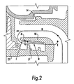
- a wall part of the back flow affecting means facing towards the inlet forms an angle with the plane of the bottom wall which preferably should be in the range 85 to 95 degrees.
- the back flow affecting means acts to affect the back flow, containing pollutions, entering the space between the impeller and the bottom wall so that the pollutions, such as abrasive particles, to a great extent are prevented from reaching the gap, or the amount at least greatly reduced. Most of the particles will enter the grooves or space between the ridges and due to the spiral shape, the particles will be transported to the periphery of the bottom plate, and out through the outlet.
- the pump shown in Fig. 1 comprises a drive shaft 10 connected to an electrical motor (not shown) for driving the pump.
- a pump impeller 12 is mounted, comprising upper 14 and lower 16 cover discs, vanes 18 and back vanes 19.
- the above mentioned components are mounted in a pump housing 20, having a bottom wall 22, an inlet 24 and an outlet 26.
- the pump impeller 12 is mounted such in the pump housing that there is a gap 28 between the peripheral surface of the lower cover disc 16 and an inner side wall of the pump housing 20, a space 29 between the lower disc and the bottom wall as well as a gap 30 between a lower surface of the lower cover disc 16 and an upper surface of the bottom wall 22.
- the liquid is sucked in axially through the inlet 24 and leaves the pump through the outlet 26 according to flow arrows A, B and C. Because the pressure is much higher at the outlet than at the inlet, however a certain flow D will always flow back through the gap 28 and into the space 29 between the lower cover disc 16 and the bottom 22 of the pump housing. A part of this flow E passes the gap 30 back to the inlet, while a part of the flow F is again led outwards on the underside of the cover disc 16, so called boundary layer flow. A boundary layer flow is also present along the bottom wall, but directed inwards.
- the back flow D creates losses and also results in that pollution, abrasive particles and the like, are gathered under the cover disc because particles of a certain size cannot pass the gap 30. This gathering of particles will then wear against pump impeller as well as against the bottom of the pump housing during running of the pump. Particles entering the gap 30 will act as grinders, with heavy wear on the surfaces of the gap. This may in a short time mean a considerable deterioration of the pump capacity because the gap is worn larger.
- the bottom wall of the pump housing facing the lower surface of the lower cover disc of the impeller is arranged with one or several swept flow affecting means, in the embodiment shown spiral grooves 32 divided by ridges.
- the grooves wind spirally around the inlet opening 24 several turns.
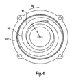
- the flow affecting means are swept such that the radial distance r from the centre is increased in the rotational direction R d of the impeller, as seen in Fig. 4.
- the grooves will affect the main flow D and the particles contained in the flow such that the water volume entering the space is moved in a tangential direction, due to the rotation of the impeller, and where the water volume is moved along the swept flow affecting means.
- This action causes the particles in the water to be moved in the grooves between the ridges in the rotational direction and due to the swept, and preferably spiral, shape of the grooves the pollutions will be fed along the grooves and out through the outlet, or at least be prevented from gathering in the gap.
- the radial component of the boundary layer flow along the bottom wall is affected such that it is directed more in the tangential direction, thus also affecting the part of the water volume in the bottom of the grooves to be moved in the direction of the swept back flow affecting means.
- the distance could be smaller if the tolerances of the impeller wheel and the bottom wall where to be tighter, or if the bottom wall, or at least the ridges, where made of a resilient material such as rubber, which would allow some contact between the parts during use.
- the depth of the grooves and the distance between ridges in the radial direction, thus the volume in the grooves, has to be taken into account so that preferably the whole water volume is affected by the process.
- the sweeping angle ⁇ of the spiral ridges also have an influence in affecting the direction of the flow and the feeding of particles in the grooves. It should in principle be possible to have straight edges of the flow affecting means with an angle to the radial direction, even though this design is not optimal for transporting particles towards the periphery of the impeller wheel.
- an angle ⁇ between the back surface and a plane parallel with the bottom of the pump housing should preferably be in the range 85 to 95 degrees, Fig. 2.
- this range is not obtainable, at least not with cast metal bottom wall.
- Tests have however shown a satisfactory result with a design according to Fig. 3. If the bottom wall according to Fig. 3, or at least the flow affecting means, where to be made of a resilient material the ridges could be cast with an angle according to the above range.
- the flow affecting means could either be grooves machined or cast in the bottom plate, or ridges attached to or cast in the bottom plate.
- the ridges or grooves may have different design.
- the bottom plate shown in the drawings is made with integral back flow affecting means, but of course the back flow affecting means could be made as a separate part which is attached in a suitable way to the bottom wall.
- the lower cover disc may be arranged with back vanes turned towards the bottom wall containing the grooves/ridges. Such back vanes however constitute a certain energy loss and are therefore used only under especially difficult conditions.
Landscapes
- Engineering & Computer Science (AREA)
- Mechanical Engineering (AREA)
- General Engineering & Computer Science (AREA)
- Structures Of Non-Positive Displacement Pumps (AREA)
- Iron Core Of Rotating Electric Machines (AREA)
Claims (4)
- Zentrifugalpumpe zum Pumpen von Flüssigkeiten, die Verunreinigungen in erster Linie in Form von festen Stoffen enthalten, wobei die Pumpe eine Antriebseinheit und eine Hydraulikeinheit aufweist, wobei die Hydraulikeinheit ein Pumpengehäuse (20) und ein Pumpenlaufrad (12) aufweist, das im Inneren des Gehäuses drehbar angeordnet ist, wobei das Pumpenlaufrad (12) eine obere (14) und eine untere (16) Abdeckscheibe und eine Anzahl zwischengeordneter Schaufeln (18) aufweist,
dadurch gekennzeichnet, dass eine Bodenwand (22) des Pumpengehäuses, die eine zentrale Einlassöffnung (24) aufweist, mit wenigstens einer spiralig verlaufenden, ein Zurückströmen unterbindenden Einrichtung (32, 34) auf der der unteren Abdeckscheibe gegenüberliegenden Seite ausgebildet ist, die sich in teilweisen oder in vollständigen Windungen um die Einlassöffnung herum erstreckt. - Zentrifugalpumpe nach Anspruch 1,
dadurch gekennzeichnet, dass die ein Zurückströmen unterbindende Einrichtung in Form von Nuten (32) in der Bodenwand ausgebildet ist. - Zentrifugalpumpe nach Anspruch 1,
dadurch gekennzeichnet, dass die ein Zurückströmen unterbindende Einrichtung in Form von Rippen (34) auf der Bodenwand gebildet ist. - Zentrifugalpumpe nach einem der vorausgehenden Ansprüche,
dadurch gekennzeichnet, dass ein in Richtung auf den Einlass weisender Wandbereich der ein Zurückströmen unterbindenden Einrichtung mit der Ebene der Bodenwand einen Winkel (β) bildet, der im Bereich von 85 bis 95 Grad liegt.
Priority Applications (1)
| Application Number | Priority Date | Filing Date | Title |
|---|---|---|---|
| PL04793806T PL1692397T3 (pl) | 2003-10-20 | 2004-10-20 | Pompa odśrodkowa |
Applications Claiming Priority (2)
| Application Number | Priority Date | Filing Date | Title |
|---|---|---|---|
| SE0302752A SE525412C2 (sv) | 2003-10-20 | 2003-10-20 | Centrifugalpump |
| PCT/SE2004/001503 WO2005038260A1 (en) | 2003-10-20 | 2004-10-20 | Centrifugal pump |
Publications (2)
| Publication Number | Publication Date |
|---|---|
| EP1692397A1 EP1692397A1 (de) | 2006-08-23 |
| EP1692397B1 true EP1692397B1 (de) | 2007-05-02 |
Family
ID=29398761
Family Applications (1)
| Application Number | Title | Priority Date | Filing Date |
|---|---|---|---|
| EP04793806A Expired - Lifetime EP1692397B1 (de) | 2003-10-20 | 2004-10-20 | Zentrifugalpumpe |
Country Status (25)
| Country | Link |
|---|---|
| US (1) | US7766605B2 (de) |
| EP (1) | EP1692397B1 (de) |
| JP (1) | JP4555298B2 (de) |
| KR (1) | KR101148852B1 (de) |
| CN (2) | CN101260888A (de) |
| AP (1) | AP2131A (de) |
| AT (1) | ATE361429T1 (de) |
| AU (1) | AU2004281359B2 (de) |
| BR (1) | BRPI0415669B1 (de) |
| CA (1) | CA2541927C (de) |
| DE (1) | DE602004006301T2 (de) |
| DK (1) | DK1692397T3 (de) |
| EA (1) | EA007556B1 (de) |
| ES (1) | ES2286690T3 (de) |
| IL (1) | IL174644A (de) |
| MX (1) | MXPA06003783A (de) |
| NO (1) | NO337153B1 (de) |
| NZ (1) | NZ546583A (de) |
| PL (1) | PL1692397T3 (de) |
| PT (1) | PT1692397E (de) |
| SE (1) | SE525412C2 (de) |
| SI (1) | SI1692397T1 (de) |
| UA (1) | UA86597C2 (de) |
| WO (1) | WO2005038260A1 (de) |
| ZA (1) | ZA200602909B (de) |
Families Citing this family (27)
| Publication number | Priority date | Publication date | Assignee | Title |
|---|---|---|---|---|
| SE527964C2 (sv) * | 2005-07-01 | 2006-07-25 | Itt Mfg Enterprises Inc | Pump för att pumpa förorenad vätska inkluderande fast material |
| DE102008030112A1 (de) * | 2008-06-27 | 2009-12-31 | Ksb Aktiengesellschaft | Kreiselpumpe mit Freistromlaufrad |
| EP2386030B1 (de) * | 2009-01-09 | 2018-06-20 | Sulzer Management AG | Zentrifugalpumpe mit einer vorrichtung zur entfernung von partikeln |
| EP2348220B1 (de) * | 2009-12-30 | 2015-07-08 | Grundfos Management A/S | Tauchpumpe |
| RU2422679C1 (ru) * | 2009-12-30 | 2011-06-27 | Шлюмберже Текнолоджи Б.В. | Ступень погружного насоса |
| CN109185163A (zh) | 2010-07-21 | 2019-01-11 | Itt制造企业有限责任公司 | 用于旋转固体处理装备的磨损减少装置 |
| CN102852860A (zh) * | 2011-12-29 | 2013-01-02 | 江苏大学 | 一种可以减小离心泵进口回流的端盖 |
| US20140030086A1 (en) * | 2012-07-26 | 2014-01-30 | GM Global Technology Operations LLC | Centrifugal pump |
| US10514042B2 (en) * | 2013-06-21 | 2019-12-24 | Flow Control LLC | Debris removing impeller back vane |
| JP6415116B2 (ja) * | 2014-05-30 | 2018-10-31 | 株式会社荏原製作所 | 汚水ポンプ用のケーシングライナ及びこれを備えた汚水ポンプ |
| DE102014012764A1 (de) * | 2014-09-02 | 2016-03-03 | Man Diesel & Turbo Se | Radialverdichterstufe |
| JP2016061241A (ja) * | 2014-09-18 | 2016-04-25 | 三菱重工業株式会社 | 遠心羽根車及び遠心圧縮機 |
| WO2016158666A1 (ja) * | 2015-03-27 | 2016-10-06 | 株式会社 荏原製作所 | 渦巻ポンプ |
| AU2016259326B2 (en) * | 2015-11-17 | 2021-02-11 | Cornell Pump Company LLC | Pump with front deflector vanes, wear plate, and impeller with pump-out vanes |
| DK179446B1 (en) * | 2015-12-22 | 2018-10-11 | F.P. Production. Grindsted Aps | A pump for pumping a liquid or slurry |
| CN105757001A (zh) * | 2016-04-26 | 2016-07-13 | 浙江理工大学 | 一种前泵腔具有平行四边形齿状结构的离心泵 |
| EA202191002A1 (ru) * | 2017-10-12 | 2021-09-09 | Уэйр Минералз Острэйлиа Лтд | Впускной компонент для шламового насоса |
| NO344723B1 (no) * | 2018-05-16 | 2020-03-23 | Tore Hystad | Sentrifugalpumpe |
| KR102165036B1 (ko) * | 2018-10-01 | 2020-10-13 | 한세구 | 슬러지 배출 타입의 흡입 커버를 갖는 수중 펌프 |
| CN111852955B (zh) | 2020-06-16 | 2021-10-12 | 江苏大学 | 一种用于改善闭式叶轮回流的泵前腔自动补偿装置 |
| WO2022087675A1 (en) * | 2020-10-29 | 2022-05-05 | Weir Minerals Australia Ltd | Grooved side liner for centrifugal pump |
| EP4056852A1 (de) * | 2021-03-09 | 2022-09-14 | Metso Outotec Sweden AB | Schlammpumpe |
| DE102021110936A1 (de) | 2021-04-28 | 2022-11-03 | Herborner Pumpentechnik Gmbh & Co Kg | Pumpenlaufrad, Gehäuseelement und Pumpe hiermit |
| WO2022266725A1 (en) * | 2021-06-25 | 2022-12-29 | Weir Minerals Australia Ltd | Centrifugal pump impeller with tapered shroud |
| CN114790989A (zh) * | 2022-03-23 | 2022-07-26 | 江苏大学流体机械温岭研究院 | 一种防堵塞抗磨损多级泵 |
| KR102532585B1 (ko) * | 2022-10-24 | 2023-05-12 | 고일영 | 슬러지 막힘 방지 및 와류 형성 구조를 갖는 흡입커버 및 이를 포함한 수중펌프 |
| KR102668812B1 (ko) | 2023-10-30 | 2024-05-24 | 고일영 | 수중펌프의 이물질 막힘 방지용 흡입커버 구조 |
Family Cites Families (16)
| Publication number | Priority date | Publication date | Assignee | Title |
|---|---|---|---|---|
| US1634317A (en) | 1925-07-22 | 1927-07-05 | Worthington Pump & Mach Corp | Impeller balancing and sealing device |
| US1879803A (en) * | 1930-01-27 | 1932-09-27 | Andrew G Johnson | Rotary pump |
| US3620642A (en) | 1969-12-09 | 1971-11-16 | Wilfley & Sons Inc A | Centrifugal pump |
| JPS4945401A (de) * | 1972-09-08 | 1974-04-30 | ||
| JPS531301A (en) * | 1976-06-28 | 1978-01-09 | Hitachi Ltd | Means for reducing shaft thrust in centrifugal turbo-machine |
| CH627236A5 (de) | 1978-02-14 | 1981-12-31 | Martin Staehle | |
| JPS57153999A (en) | 1981-03-20 | 1982-09-22 | Hitachi Ltd | Casing of centrifugal pump |
| JPH064073Y2 (ja) * | 1985-01-21 | 1994-02-02 | 日本碍子株式会社 | ポンプ |
| SU1528035A1 (ru) * | 1987-02-18 | 1994-10-30 | А.И. Золотарь | Центробежный насос |
| SE466766B (sv) | 1989-04-27 | 1992-03-30 | Flygt Ab Itt | Centrifugalpump avsedd foer pumpning av vaetskor innehaallande fasta partiklar, exempelvis trasor och andra laangstraeckta foeremaal |
| JPH0445401A (ja) | 1990-06-13 | 1992-02-14 | Mitsubishi Gas Chem Co Inc | 高アッベ数レンズ |
| JP3277559B2 (ja) | 1992-06-18 | 2002-04-22 | カシオ計算機株式会社 | 効果付加装置 |
| EP0721546B1 (de) | 1993-09-25 | 1998-12-02 | KSB Aktiengesellschaft | Strömungsmaschine mit verringertem abrasiven verschleiss |
| DE4338931C2 (de) * | 1993-11-15 | 1996-09-05 | Wilo Gmbh | Verstopfungsfreie Kreiselpumpe |
| JPH094585A (ja) * | 1995-06-20 | 1997-01-07 | Torishima Pump Mfg Co Ltd | 汚水ポンプ |
| US7465153B2 (en) | 2001-08-08 | 2008-12-16 | Addie Graeme R | Diverter for reducing wear in a slurry pump |
-
2003
- 2003-10-20 SE SE0302752A patent/SE525412C2/sv not_active IP Right Cessation
-
2004
- 2004-10-20 EP EP04793806A patent/EP1692397B1/de not_active Expired - Lifetime
- 2004-10-20 US US10/576,322 patent/US7766605B2/en active Active
- 2004-10-20 DE DE602004006301T patent/DE602004006301T2/de not_active Expired - Lifetime
- 2004-10-20 DK DK04793806T patent/DK1692397T3/da active
- 2004-10-20 ES ES04793806T patent/ES2286690T3/es not_active Expired - Lifetime
- 2004-10-20 SI SI200430391T patent/SI1692397T1/sl unknown
- 2004-10-20 CN CNA2007101262891A patent/CN101260888A/zh active Pending
- 2004-10-20 JP JP2006535315A patent/JP4555298B2/ja not_active Expired - Fee Related
- 2004-10-20 AP AP2006003574A patent/AP2131A/en active
- 2004-10-20 AU AU2004281359A patent/AU2004281359B2/en not_active Expired
- 2004-10-20 CN CNB2004800309255A patent/CN100564885C/zh not_active Expired - Fee Related
- 2004-10-20 AT AT04793806T patent/ATE361429T1/de active
- 2004-10-20 PL PL04793806T patent/PL1692397T3/pl unknown
- 2004-10-20 KR KR1020067007582A patent/KR101148852B1/ko active IP Right Grant
- 2004-10-20 PT PT04793806T patent/PT1692397E/pt unknown
- 2004-10-20 WO PCT/SE2004/001503 patent/WO2005038260A1/en active IP Right Grant
- 2004-10-20 BR BRPI0415669A patent/BRPI0415669B1/pt not_active IP Right Cessation
- 2004-10-20 ZA ZA200602909A patent/ZA200602909B/en unknown
- 2004-10-20 CA CA2541927A patent/CA2541927C/en not_active Expired - Fee Related
- 2004-10-20 NZ NZ546583A patent/NZ546583A/en unknown
- 2004-10-20 UA UAA200603522A patent/UA86597C2/ru unknown
- 2004-10-20 EA EA200600806A patent/EA007556B1/ru unknown
- 2004-10-20 MX MXPA06003783A patent/MXPA06003783A/es active IP Right Grant
-
2006
- 2006-03-30 IL IL174644A patent/IL174644A/en active IP Right Grant
- 2006-05-19 NO NO20062278A patent/NO337153B1/no not_active IP Right Cessation
Also Published As
Similar Documents
| Publication | Publication Date | Title |
|---|---|---|
| EP1692397B1 (de) | Zentrifugalpumpe | |
| EP3196469B1 (de) | Pumpenanordnung umfassend eine strömungsleitvorrichtung mit zirkulationsdurchgängen und zuführungsdurchgängen | |
| US4904159A (en) | Pump impeller | |
| US7465153B2 (en) | Diverter for reducing wear in a slurry pump | |
| KR101737420B1 (ko) | 수중 슬러지 이송용 펌프 임펠러 | |
| WO2005045254A2 (en) | Improved impeller and wear plate | |
| EP1092094B1 (de) | Zentrifugalpumpe | |
| CA2585171A1 (en) | Impeller wheel | |
| US20040136825A1 (en) | Multiple diverter for reducing wear in a slurry pump | |
| US5542817A (en) | Impeller for a rotary pump | |
| CN116194674A (zh) | 用于配置为泵送包含磨料的液体的潜水泵的开式叶轮 | |
| AU2016201972B2 (en) | Improvements in and relating to pumps | |
| JPH05321867A (ja) | 混流羽根と遠心羽根を一体化した複合インペラー | |
| US20220145890A1 (en) | Cutting system for a grinding pump and related grinding pump | |
| SU1055542A1 (ru) | Импеллерный блок флотационной машины |
Legal Events
| Date | Code | Title | Description |
|---|---|---|---|
| PUAI | Public reference made under article 153(3) epc to a published international application that has entered the european phase |
Free format text: ORIGINAL CODE: 0009012 |
|
| 17P | Request for examination filed |
Effective date: 20060424 |
|
| AK | Designated contracting states |
Kind code of ref document: A1 Designated state(s): AT BE BG CH CY CZ DE DK EE ES FI FR GB GR HU IE IT LI LU MC NL PL PT RO SE SI SK TR |
|
| AX | Request for extension of the european patent |
Extension state: LT LV |
|
| GRAP | Despatch of communication of intention to grant a patent |
Free format text: ORIGINAL CODE: EPIDOSNIGR1 |
|
| RAX | Requested extension states of the european patent have changed |
Extension state: LT Payment date: 20060424 Extension state: LV Payment date: 20060424 |
|
| GRAS | Grant fee paid |
Free format text: ORIGINAL CODE: EPIDOSNIGR3 |
|
| GRAA | (expected) grant |
Free format text: ORIGINAL CODE: 0009210 |
|
| AK | Designated contracting states |
Kind code of ref document: B1 Designated state(s): AT BE BG CH CY CZ DE DK EE ES FI FR GB GR HU IE IT LI LU MC NL PL PT RO SE SI SK TR |
|
| AX | Request for extension of the european patent |
Extension state: LT LV |
|
| REG | Reference to a national code |
Ref country code: GB Ref legal event code: FG4D |
|
| RIN1 | Information on inventor provided before grant (corrected) |
Inventor name: LINDSKOG, MARTIN |
|
| REG | Reference to a national code |
Ref country code: CH Ref legal event code: EP |
|
| REG | Reference to a national code |
Ref country code: IE Ref legal event code: FG4D |
|
| REF | Corresponds to: |
Ref document number: 602004006301 Country of ref document: DE Date of ref document: 20070614 Kind code of ref document: P |
|
| REG | Reference to a national code |
Ref country code: RO Ref legal event code: EPE |
|
| REG | Reference to a national code |
Ref country code: SE Ref legal event code: TRGR Ref country code: CH Ref legal event code: NV Representative=s name: WILLIAM BLANC & CIE CONSEILS EN PROPRIETE INDUSTRI |
|
| REG | Reference to a national code |
Ref country code: PT Ref legal event code: SC4A Free format text: AVAILABILITY OF NATIONAL TRANSLATION Effective date: 20070731 |
|
| REG | Reference to a national code |
Ref country code: GR Ref legal event code: EP Ref document number: 20070402206 Country of ref document: GR |
|
| REG | Reference to a national code |
Ref country code: DK Ref legal event code: T3 |
|
| REG | Reference to a national code |
Ref country code: PL Ref legal event code: T3 |
|
| ET | Fr: translation filed | ||
| REG | Reference to a national code |
Ref country code: ES Ref legal event code: FG2A Ref document number: 2286690 Country of ref document: ES Kind code of ref document: T3 |
|
| REG | Reference to a national code |
Ref country code: HU Ref legal event code: AG4A Ref document number: E002076 Country of ref document: HU |
|
| PLBE | No opposition filed within time limit |
Free format text: ORIGINAL CODE: 0009261 |
|
| STAA | Information on the status of an ep patent application or granted ep patent |
Free format text: STATUS: NO OPPOSITION FILED WITHIN TIME LIMIT |
|
| 26N | No opposition filed |
Effective date: 20080205 |
|
| PG25 | Lapsed in a contracting state [announced via postgrant information from national office to epo] |
Ref country code: MC Free format text: LAPSE BECAUSE OF NON-PAYMENT OF DUE FEES Effective date: 20071031 |
|
| PG25 | Lapsed in a contracting state [announced via postgrant information from national office to epo] |
Ref country code: CY Free format text: LAPSE BECAUSE OF FAILURE TO SUBMIT A TRANSLATION OF THE DESCRIPTION OR TO PAY THE FEE WITHIN THE PRESCRIBED TIME-LIMIT Effective date: 20070502 |
|
| PG25 | Lapsed in a contracting state [announced via postgrant information from national office to epo] |
Ref country code: LU Free format text: LAPSE BECAUSE OF NON-PAYMENT OF DUE FEES Effective date: 20071020 |
|
| REG | Reference to a national code |
Ref country code: CH Ref legal event code: PFA Owner name: ITT MANUFACTURING ENTERPRISES, INC. Free format text: ITT MANUFACTURING ENTERPRISES, INC.#1105 NORTH MARKET STREET#WILMINGTON, DELAWARE 19801 (US) -TRANSFER TO- ITT MANUFACTURING ENTERPRISES, INC.#1105 NORTH MARKET STREET#WILMINGTON, DELAWARE 19801 (US) |
|
| REG | Reference to a national code |
Ref country code: CH Ref legal event code: PCAR Free format text: NOVAGRAAF SWITZERLAND SA;CHEMIN DE L'ECHO 3;1213 ONEX (CH) |
|
| REG | Reference to a national code |
Ref country code: GB Ref legal event code: 732E Free format text: REGISTERED BETWEEN 20120621 AND 20120627 |
|
| REG | Reference to a national code |
Ref country code: DE Ref legal event code: R082 Ref document number: 602004006301 Country of ref document: DE Representative=s name: KLUNKER, SCHMITT-NILSON, HIRSCH, DE |
|
| REG | Reference to a national code |
Ref country code: DE Ref legal event code: R082 Ref document number: 602004006301 Country of ref document: DE Representative=s name: SCHMITT-NILSON SCHRAUD WAIBEL WOHLFROM PATENTA, DE Effective date: 20120917 Ref country code: DE Ref legal event code: R081 Ref document number: 602004006301 Country of ref document: DE Owner name: XYLEM IP HOLDINGS LLC, US Free format text: FORMER OWNER: ITT MFG. ENTERPRISES, INC., WILMINGTON, US Effective date: 20120917 Ref country code: DE Ref legal event code: R082 Ref document number: 602004006301 Country of ref document: DE Representative=s name: KLUNKER, SCHMITT-NILSON, HIRSCH, DE Effective date: 20120917 Ref country code: DE Ref legal event code: R081 Ref document number: 602004006301 Country of ref document: DE Owner name: XYLEM IP HOLDINGS LLC, WHITE PLAINS, US Free format text: FORMER OWNER: ITT MFG. ENTERPRISES, INC., WILMINGTON, DEL., US Effective date: 20120917 |
|
| REG | Reference to a national code |
Ref country code: FR Ref legal event code: TP Owner name: XYLEM IP HOLDINGS LLC, US Effective date: 20121015 |
|
| REG | Reference to a national code |
Ref country code: ES Ref legal event code: PC2A Owner name: XYLEM IP HOLDINGS LLC Effective date: 20130130 |
|
| REG | Reference to a national code |
Ref country code: FR Ref legal event code: PLFP Year of fee payment: 12 |
|
| REG | Reference to a national code |
Ref country code: FR Ref legal event code: PLFP Year of fee payment: 13 |
|
| PGFP | Annual fee paid to national office [announced via postgrant information from national office to epo] |
Ref country code: GR Payment date: 20161027 Year of fee payment: 13 Ref country code: RO Payment date: 20161006 Year of fee payment: 13 Ref country code: BG Payment date: 20161028 Year of fee payment: 13 |
|
| REG | Reference to a national code |
Ref country code: DE Ref legal event code: R082 Ref document number: 602004006301 Country of ref document: DE Representative=s name: SCHMITT-NILSON SCHRAUD WAIBEL WOHLFROM PATENTA, DE |
|
| REG | Reference to a national code |
Ref country code: FR Ref legal event code: PLFP Year of fee payment: 14 |
|
| PG25 | Lapsed in a contracting state [announced via postgrant information from national office to epo] |
Ref country code: GR Free format text: LAPSE BECAUSE OF NON-PAYMENT OF DUE FEES Effective date: 20180504 Ref country code: RO Free format text: LAPSE BECAUSE OF NON-PAYMENT OF DUE FEES Effective date: 20171020 |
|
| REG | Reference to a national code |
Ref country code: FR Ref legal event code: PLFP Year of fee payment: 15 |
|
| PG25 | Lapsed in a contracting state [announced via postgrant information from national office to epo] |
Ref country code: BG Free format text: LAPSE BECAUSE OF NON-PAYMENT OF DUE FEES Effective date: 20180506 |
|
| PGFP | Annual fee paid to national office [announced via postgrant information from national office to epo] |
Ref country code: NL Payment date: 20201026 Year of fee payment: 17 |
|
| PGFP | Annual fee paid to national office [announced via postgrant information from national office to epo] |
Ref country code: CZ Payment date: 20201006 Year of fee payment: 17 Ref country code: EE Payment date: 20201001 Year of fee payment: 17 Ref country code: PT Payment date: 20201001 Year of fee payment: 17 |
|
| PGFP | Annual fee paid to national office [announced via postgrant information from national office to epo] |
Ref country code: SK Payment date: 20201001 Year of fee payment: 17 Ref country code: SI Payment date: 20201002 Year of fee payment: 17 |
|
| PGFP | Annual fee paid to national office [announced via postgrant information from national office to epo] |
Ref country code: FI Payment date: 20211027 Year of fee payment: 18 Ref country code: DK Payment date: 20211027 Year of fee payment: 18 |
|
| PGFP | Annual fee paid to national office [announced via postgrant information from national office to epo] |
Ref country code: CH Payment date: 20211103 Year of fee payment: 18 Ref country code: BE Payment date: 20211027 Year of fee payment: 18 |
|
| REG | Reference to a national code |
Ref country code: EE Ref legal event code: MM4A Ref document number: E001413 Country of ref document: EE Effective date: 20211031 |
|
| REG | Reference to a national code |
Ref country code: NL Ref legal event code: MM Effective date: 20211101 |
|
| REG | Reference to a national code |
Ref country code: SK Ref legal event code: MM4A Ref document number: E 2492 Country of ref document: SK Effective date: 20211020 |
|
| PG25 | Lapsed in a contracting state [announced via postgrant information from national office to epo] |
Ref country code: SK Free format text: LAPSE BECAUSE OF NON-PAYMENT OF DUE FEES Effective date: 20211020 Ref country code: PT Free format text: LAPSE BECAUSE OF NON-PAYMENT OF DUE FEES Effective date: 20220420 Ref country code: NL Free format text: LAPSE BECAUSE OF NON-PAYMENT OF DUE FEES Effective date: 20211101 Ref country code: EE Free format text: LAPSE BECAUSE OF NON-PAYMENT OF DUE FEES Effective date: 20211031 Ref country code: CZ Free format text: LAPSE BECAUSE OF NON-PAYMENT OF DUE FEES Effective date: 20211020 |
|
| PG25 | Lapsed in a contracting state [announced via postgrant information from national office to epo] |
Ref country code: SI Free format text: LAPSE BECAUSE OF NON-PAYMENT OF DUE FEES Effective date: 20211021 |
|
| PGFP | Annual fee paid to national office [announced via postgrant information from national office to epo] |
Ref country code: FR Payment date: 20221025 Year of fee payment: 19 |
|
| PGFP | Annual fee paid to national office [announced via postgrant information from national office to epo] |
Ref country code: TR Payment date: 20221018 Year of fee payment: 19 Ref country code: IT Payment date: 20221020 Year of fee payment: 19 Ref country code: GB Payment date: 20221027 Year of fee payment: 19 Ref country code: DE Payment date: 20221027 Year of fee payment: 19 Ref country code: AT Payment date: 20221004 Year of fee payment: 19 |
|
| PGFP | Annual fee paid to national office [announced via postgrant information from national office to epo] |
Ref country code: PL Payment date: 20221003 Year of fee payment: 19 Ref country code: HU Payment date: 20221015 Year of fee payment: 19 |
|
| REG | Reference to a national code |
Ref country code: DK Ref legal event code: EBP Effective date: 20221031 |
|
| REG | Reference to a national code |
Ref country code: CH Ref legal event code: PL |
|
| REG | Reference to a national code |
Ref country code: BE Ref legal event code: MM Effective date: 20221031 |
|
| PG25 | Lapsed in a contracting state [announced via postgrant information from national office to epo] |
Ref country code: LI Free format text: LAPSE BECAUSE OF NON-PAYMENT OF DUE FEES Effective date: 20221031 Ref country code: CH Free format text: LAPSE BECAUSE OF NON-PAYMENT OF DUE FEES Effective date: 20221031 |
|
| PG25 | Lapsed in a contracting state [announced via postgrant information from national office to epo] |
Ref country code: BE Free format text: LAPSE BECAUSE OF NON-PAYMENT OF DUE FEES Effective date: 20221031 |
|
| PG25 | Lapsed in a contracting state [announced via postgrant information from national office to epo] |
Ref country code: DK Free format text: LAPSE BECAUSE OF NON-PAYMENT OF DUE FEES Effective date: 20221031 |
|
| PGFP | Annual fee paid to national office [announced via postgrant information from national office to epo] |
Ref country code: ES Payment date: 20231102 Year of fee payment: 20 |
|
| PGFP | Annual fee paid to national office [announced via postgrant information from national office to epo] |
Ref country code: SE Payment date: 20231027 Year of fee payment: 20 Ref country code: IE Payment date: 20231027 Year of fee payment: 20 |
|
| PG25 | Lapsed in a contracting state [announced via postgrant information from national office to epo] |
Ref country code: FI Free format text: LAPSE BECAUSE OF NON-PAYMENT OF DUE FEES Effective date: 20221020 |
|
| REG | Reference to a national code |
Ref country code: DE Ref legal event code: R119 Ref document number: 602004006301 Country of ref document: DE |
|
| REG | Reference to a national code |
Ref country code: AT Ref legal event code: MM01 Ref document number: 361429 Country of ref document: AT Kind code of ref document: T Effective date: 20231020 |
|
| GBPC | Gb: european patent ceased through non-payment of renewal fee |
Effective date: 20231020 |
|
| PG25 | Lapsed in a contracting state [announced via postgrant information from national office to epo] |
Ref country code: GB Free format text: LAPSE BECAUSE OF NON-PAYMENT OF DUE FEES Effective date: 20231020 |
|
| PG25 | Lapsed in a contracting state [announced via postgrant information from national office to epo] |
Ref country code: AT Free format text: LAPSE BECAUSE OF NON-PAYMENT OF DUE FEES Effective date: 20231020 |
|
| PG25 | Lapsed in a contracting state [announced via postgrant information from national office to epo] |
Ref country code: GB Free format text: LAPSE BECAUSE OF NON-PAYMENT OF DUE FEES Effective date: 20231020 Ref country code: FR Free format text: LAPSE BECAUSE OF NON-PAYMENT OF DUE FEES Effective date: 20231031 Ref country code: DE Free format text: LAPSE BECAUSE OF NON-PAYMENT OF DUE FEES Effective date: 20240501 Ref country code: AT Free format text: LAPSE BECAUSE OF NON-PAYMENT OF DUE FEES Effective date: 20231020 |
|
| PG25 | Lapsed in a contracting state [announced via postgrant information from national office to epo] |
Ref country code: HU Free format text: LAPSE BECAUSE OF NON-PAYMENT OF DUE FEES Effective date: 20231021 |