EP1690087B1 - Beschichtete testelemente - Google Patents
Beschichtete testelemente Download PDFInfo
- Publication number
- EP1690087B1 EP1690087B1 EP04803503.4A EP04803503A EP1690087B1 EP 1690087 B1 EP1690087 B1 EP 1690087B1 EP 04803503 A EP04803503 A EP 04803503A EP 1690087 B1 EP1690087 B1 EP 1690087B1
- Authority
- EP
- European Patent Office
- Prior art keywords
- test element
- accordance
- test
- magazine
- channel
- Prior art date
- Legal status (The legal status is an assumption and is not a legal conclusion. Google has not performed a legal analysis and makes no representation as to the accuracy of the status listed.)
- Expired - Lifetime
Links
Images
Classifications
-
- B—PERFORMING OPERATIONS; TRANSPORTING
- B01—PHYSICAL OR CHEMICAL PROCESSES OR APPARATUS IN GENERAL
- B01L—CHEMICAL OR PHYSICAL LABORATORY APPARATUS FOR GENERAL USE
- B01L3/00—Containers or dishes for laboratory use, e.g. laboratory glassware; Droppers
- B01L3/50—Containers for the purpose of retaining a material to be analysed, e.g. test tubes
- B01L3/502—Containers for the purpose of retaining a material to be analysed, e.g. test tubes with fluid transport, e.g. in multi-compartment structures
- B01L3/5027—Containers for the purpose of retaining a material to be analysed, e.g. test tubes with fluid transport, e.g. in multi-compartment structures by integrated microfluidic structures, i.e. dimensions of channels and chambers are such that surface tension forces are important, e.g. lab-on-a-chip
- B01L3/502715—Containers for the purpose of retaining a material to be analysed, e.g. test tubes with fluid transport, e.g. in multi-compartment structures by integrated microfluidic structures, i.e. dimensions of channels and chambers are such that surface tension forces are important, e.g. lab-on-a-chip characterised by interfacing components, e.g. fluidic, electrical, optical or mechanical interfaces
-
- B—PERFORMING OPERATIONS; TRANSPORTING
- B01—PHYSICAL OR CHEMICAL PROCESSES OR APPARATUS IN GENERAL
- B01L—CHEMICAL OR PHYSICAL LABORATORY APPARATUS FOR GENERAL USE
- B01L3/00—Containers or dishes for laboratory use, e.g. laboratory glassware; Droppers
- B01L3/50—Containers for the purpose of retaining a material to be analysed, e.g. test tubes
- B01L3/502—Containers for the purpose of retaining a material to be analysed, e.g. test tubes with fluid transport, e.g. in multi-compartment structures
- B01L3/5027—Containers for the purpose of retaining a material to be analysed, e.g. test tubes with fluid transport, e.g. in multi-compartment structures by integrated microfluidic structures, i.e. dimensions of channels and chambers are such that surface tension forces are important, e.g. lab-on-a-chip
- B01L3/502707—Containers for the purpose of retaining a material to be analysed, e.g. test tubes with fluid transport, e.g. in multi-compartment structures by integrated microfluidic structures, i.e. dimensions of channels and chambers are such that surface tension forces are important, e.g. lab-on-a-chip characterised by the manufacture of the container or its components
-
- A—HUMAN NECESSITIES
- A61—MEDICAL OR VETERINARY SCIENCE; HYGIENE
- A61B—DIAGNOSIS; SURGERY; IDENTIFICATION
- A61B2562/00—Details of sensors; Constructional details of sensor housings or probes; Accessories for sensors
- A61B2562/02—Details of sensors specially adapted for in-vivo measurements
- A61B2562/0295—Strip shaped analyte sensors for apparatus classified in A61B5/145 or A61B5/157
-
- B—PERFORMING OPERATIONS; TRANSPORTING
- B01—PHYSICAL OR CHEMICAL PROCESSES OR APPARATUS IN GENERAL
- B01L—CHEMICAL OR PHYSICAL LABORATORY APPARATUS FOR GENERAL USE
- B01L2200/00—Solutions for specific problems relating to chemical or physical laboratory apparatus
- B01L2200/02—Adapting objects or devices to another
- B01L2200/026—Fluid interfacing between devices or objects, e.g. connectors, inlet details
- B01L2200/027—Fluid interfacing between devices or objects, e.g. connectors, inlet details for microfluidic devices
-
- B—PERFORMING OPERATIONS; TRANSPORTING
- B01—PHYSICAL OR CHEMICAL PROCESSES OR APPARATUS IN GENERAL
- B01L—CHEMICAL OR PHYSICAL LABORATORY APPARATUS FOR GENERAL USE
- B01L2300/00—Additional constructional details
- B01L2300/08—Geometry, shape and general structure
- B01L2300/0809—Geometry, shape and general structure rectangular shaped
- B01L2300/0825—Test strips
-
- B—PERFORMING OPERATIONS; TRANSPORTING
- B01—PHYSICAL OR CHEMICAL PROCESSES OR APPARATUS IN GENERAL
- B01L—CHEMICAL OR PHYSICAL LABORATORY APPARATUS FOR GENERAL USE
- B01L2300/00—Additional constructional details
- B01L2300/08—Geometry, shape and general structure
- B01L2300/0887—Laminated structure
-
- B—PERFORMING OPERATIONS; TRANSPORTING
- B01—PHYSICAL OR CHEMICAL PROCESSES OR APPARATUS IN GENERAL
- B01L—CHEMICAL OR PHYSICAL LABORATORY APPARATUS FOR GENERAL USE
- B01L2300/00—Additional constructional details
- B01L2300/16—Surface properties and coatings
- B01L2300/161—Control and use of surface tension forces, e.g. hydrophobic, hydrophilic
- B01L2300/165—Specific details about hydrophobic, oleophobic surfaces
- B01L2300/166—Suprahydrophobic; Ultraphobic; Lotus-effect
-
- B—PERFORMING OPERATIONS; TRANSPORTING
- B01—PHYSICAL OR CHEMICAL PROCESSES OR APPARATUS IN GENERAL
- B01L—CHEMICAL OR PHYSICAL LABORATORY APPARATUS FOR GENERAL USE
- B01L2400/00—Moving or stopping fluids
- B01L2400/04—Moving fluids with specific forces or mechanical means
- B01L2400/0403—Moving fluids with specific forces or mechanical means specific forces
- B01L2400/0406—Moving fluids with specific forces or mechanical means specific forces capillary forces
-
- Y—GENERAL TAGGING OF NEW TECHNOLOGICAL DEVELOPMENTS; GENERAL TAGGING OF CROSS-SECTIONAL TECHNOLOGIES SPANNING OVER SEVERAL SECTIONS OF THE IPC; TECHNICAL SUBJECTS COVERED BY FORMER USPC CROSS-REFERENCE ART COLLECTIONS [XRACs] AND DIGESTS
- Y10—TECHNICAL SUBJECTS COVERED BY FORMER USPC
- Y10S—TECHNICAL SUBJECTS COVERED BY FORMER USPC CROSS-REFERENCE ART COLLECTIONS [XRACs] AND DIGESTS
- Y10S436/00—Chemistry: analytical and immunological testing
- Y10S436/807—Apparatus included in process claim, e.g. physical support structures
- Y10S436/808—Automated or kit
Definitions
- the invention relates to coated test elements, in particular test elements having a capillary gap, which have a hydrophobic structured coating at least in the area surrounding the capillary gap.
- Test elements for diagnostic devices are widely used by the patients themselves.
- the application generally involves applying a sample of body fluid, e.g. Blood, the test element, the introduction of the test element into a measuring device and the determination of an analyte from the body fluid in the measuring device. Hitherto, the whereabouts of excess sample material, e.g. Blood, left to the user alone.
- this sample material could pose a serious risk of contamination and a hygiene problem depending on the place of disposal. This problem has been particularly relevant to capillary gap test strips which often have blood adhered to the outside of the capillary.
- test elements are often pulled into or through the measuring device.
- each outside of the test element adhering sample material poses a risk of contamination of the meter.
- this risk of contamination of the meter when Remagazin michö the test strips.
- test strips are transported within the measuring device after a sample application has taken place on a test strip. Consequently, a risk of contamination exists on the one hand during test element transport after a sample has been abandoned and on the other other test elements already used by the storage within the magazine.
- sample material dried on the outside of test elements may crumble and contaminate device parts, optics and the environment.
- WO 97/46887 describes a remagazation of cuvettes or test elements.
- Superfluous sample residues eg blood residues
- the WO 99/29429 describes an analytical test element for determining an analyte in a liquid comprising an inert support, a sample material application zone, a detection zone for determining the analyte, and a channel or gap for transporting fluid from the application zone to the detection zone, at least in a range of the task zone has a hydrophobic structured surface.
- test elements and test methods in which contamination by sample material, in particular during remagazation, can be avoided as far as possible.
- test elements with hydrophobic structured surfaces, which are also known by the name lotus surfaces, it has surprisingly been found that contamination with sample material, in particular with blood, can be largely ruled out.
- test elements that have a channel opening or have a gap for receiving and transporting sample material, it has been shown that exclusive wetting of the channel opening or the gap is achieved by Lotus surfaces
- the lotus surface coating has the advantage of allowing accurate metering and thus reduction in sample volume, as will be discussed in detail below.
- the lotus surface coating is suitable for test elements having a hydrophilic capillary structure, since with such test elements contamination of the edge region of the test elements and thus of the measuring device must be expected.
- the test elements initially protrude out of the device during the blood task.
- the blood is applied by the user on the protruding from the device end of the test element on which the opening of the capillary is arranged.
- excess blood is either sucked into the capillary or drips off the test element edge, so that only the capillary gap of the test element is wetted, no blood at the area of the test element surrounding the capillary gap adheres.
- An object of the invention is thus an analytical test element for the determination of an analyte in a liquid according to claim 1.
- Hydrophobically structured surfaces or lotus effect surfaces are self-cleaning surfaces which have elevations, wherein the mean distance between elevations is preferably in the range of 50 nm to 200 microns, more preferably in the range of 50 nm to 10 microns and the average height of the elevations preferably in the range of 50 nm to 100 microns, more preferably in the range of 50 nm to 10 microns, is.
- the effect of lotus effect is preferably characterized by a surface energy of less than preferably 20 mN / m and according to the invention by a contact angle of ⁇ 120 ° and up to 160 ° with respect to aqueous systems. At least the elevations are made of hydrophobic materials, such as nanoparticles with hydrophobic properties.
- Preferred examples of surfaces with lotus effect are in EP-B-0 772 514 . EP-B-0 933 388 . EP-A-1 018 531 . EP-A-1 040 874 . EP-B-1 171 529 . EP-A-1 249 280 and EP-A-1 249 467 described.
- structured hydrophobic surfaces with lotus effect can be produced by many different methods, for example by coating, impregnating, spraying, co-extruding or by injection molding. Preference is given to spraying a suspension of hydrophobic nanoparticles.
- a method which includes a fixation of the hydrophobic structured coating on the surface of the test element is first applied to the areas of the test element to be coated, then hydrophobic particles, with suitably fissured structures, are applied to the areas to be coated and then the particles are fixed by hardening, as in EP-A-1 249 280 is described.
- Suitable curable substances are, for example, paints which comprise mono- or / and polyunsaturated acrylates and / or methacrylates and / or polyurethanes and / or silicone acrylates and / or urethane acrylates.
- the paints preferably have hydrophobic properties.
- the particles themselves may be hydrophobic, for example pulverulent polymers, in particular halogenated hydrocarbons, such as Polytetrafluoroethylene, or hydrophobized particles, such as hydrophobic aerosils be.
- the hydrophobization of the particles can also take place after fixing on the support.
- the particles are fixed by hardening, for example by thermal or chemical energy or / and by light energy.
- a hydrophobic layer applied by such a multistage process is particularly stable against abrasion and mechanical stress.
- test element which has a lotus effect surface in an area around the application zone and in particular a channel opening or a gap in the region of the task zone, a facilitated dosing of the sample liquid is made possible because the sample liquid is automatically passed to the channel opening and a Adhering to the channel opening surrounding areas of the test element is prevented. This is of particular interest to diabetic patients, who are often the elderly or partially sighted.
- test element Due to the exact dosing by the hydrophobic structured surface, it is also possible to reduce the sample volume, so that a low-pain blood collection of only very small amounts of blood is possible.
- a hydrophobic coating of the test elements is advantageous, in particular in the case of remagazineization of test elements.
- Remagazinierung the test element, which is initially from an optionally integrated into the measuring device magazine for sample application, e.g. to the task of blood, is postponed, then withdrawn back into this.
- the analytical test element coated according to the invention has a channel opening or a gap in the region of the application zone, the surface of the test element having a hydrophobic structuring at least around the channel opening.
- the surface can of the test element, at least the parts that are formed by the carrier as well as by any covers or intermediate layers that may be present, be completely coated with a hydrophobically structured coating.
- the channel is preferably a capillary channel or capillary gap, ie a channel or gap capable of capillary liquid transport to the detection zone of the test element, which optionally may have a vent at its other end adjacent to an opening in the feed zone.
- the channel preferably has at least partially in its interior a hydrophilic or hydrophilic coated surface, eg a metallic or oxidic surface.
- the channel or gap cross-section can basically be arbitrary.
- the channel or gap has a substantially rectangular cross-section whose dimensions are dictated by the physical limits of capillary activity.
- the height of the channel or gap is, for example, for aqueous sample liquids in the order of 10 to 500 .mu.m, preferably between 20 and 300 .mu.m.
- the width may then be several mm, preferably 1 to 10 mm, more preferably 1 to 3 mm, and the length up to a few cm, preferably 0.5 to 5 cm, very preferably 1 to 3 cm ,
- the edge of the test element forming the sample application zone has a recess in the area of the channel or gap forming surface to facilitate entry of sample liquid into the channel.
- the dimension of the recess eg its width, is preferably chosen so that the diameter of the drop of the sample liquid applied to the test element is slightly larger than the selected dimension of the recess.
- a width of the recess of about 1 mm has proven to be suitable.
- the exposed by the recess surface has - as well as the channel or gap itself - preferably a hydrophilic or hydrophilic coated surface.
- the test element contains a part or all of the reagents necessary for the determination of the analyte and optionally excipients.
- reagents include, for example, enzymes, enzyme substrates, indicators, buffer salts, inert fillers, and the like.
- the reagents are preferably contained in the detection zone.
- the detection zone may be composed of one or more regions and usually contains absorbent materials impregnated with the reagents. Examples of absorbent materials are nonwovens, woven fabrics, knitted fabrics or porous plastic materials, which may be in the form of, for example, layers. Preferred materials are papers or porous plastic materials such as membranes.
- the detection zone contains open films, such as in EP-B-0 016 387 are described. The films may consist of one or more layers and be applied to a support of the test element.
- the detection zone may also have components which allow exclusion of interfering sample components from the detection reaction and thus act as a filter, for example for particulate sample components such as blood cells. Suitable examples of this are semipermeable membranes or glass fiber nonwovens, as is known EP-B-0 045 476 are known.
- the determination of the analyte in the detection zone can be carried out by optical methods, e.g. by visual or photometric determination, by electrochemical methods or other suitable detection methods.
- the test element may further comprise covers and / or intermediate layers which, together with the carrier and optionally the detection zone, form the boundary of the sample transport channel or gap.
- the covers and intermediate layers may be the same or similar to the inert support in their properties, such as material and coating. Particular preference is given to the channel or
- Gap-facing side of a cover a flexible inert film attached, which extends over the entire length of the cover, the channel or gap over the entire width covered and which is at least partially enclosed between the opposite surfaces of the cover and the detection element, so that the capillary liquid transport at the point of contact of detection zone and cover does not break off.
- test elements with a capillary channel, such as those in WO 99/29429 are described.
- These test elements are distinguished by the fact that a channel or gap capable of capillary liquid transport is at least partially formed by the carrier and detection zone and extends in the direction of the capillary transport from the sample application zone at least to the edge of the detection zone closest to a vent in the test element and a recess in a channel or gap forming surface capable of capillary liquid transport, at which the sample-introducing opening edge of the test element is located such that the edge of the test element forming the sample-application opening is at least partially interrupted on one side and the surface opposite the recess is exposed.
- test element coated according to the invention is preferably provided for reception within a magazine, which may contain one or more test elements.
- the test element is intended for remagazation, ie for inclusion in a magazine, which may contain used and unused test elements, wherein an unused test element is removed from the magazine before use and returned to the magazine after use.
- the removal or / and return can be done manually or automatically.
- the single test element may be a disposable test element or a reusable test element.
- the magazine can be arranged within a measuring device which is provided, for example, for optical or electrochemical detection.
- the test element can be used to detect any analytes in liquid sample materials, in particular body fluids such as blood, saliva or urine. Particularly preferred is the determination of glucose in blood. Other preferred examples of the application of the test elements are the coagulation measurement or the measurement of HBA1C.
- the measuring device may include one or more magazines integrated for receiving one or more test elements. Preference is given to a measuring device with remagazin mandat test elements, with used and unused test elements can be present together in a magazine.
- a volume of the sample liquid for example a volume of 1 to 10 ⁇ l, is applied to the test element.
- the application takes place in the region of the task zone of the test element, wherein the surface is at least in the area around the task zone according to the invention hydrophobically structured coated to contamination by excess and / or to avoid inaccurately applied sample material.
- the determination of the analyte preferably takes place in an integrated measuring device, the test element being moved from a first position in the device, e.g. in a first magazine, to a second position, e.g. a position for sample application, then to a third position, e.g. a position for determining the analyte and then out of the device or to a fourth position, e.g. in the first or another magazine, is transported.
- the device may include one or more magazines each provided for receiving one or more test elements. Particularly preferred is a device with a magazine in which used and unused test elements are present together.
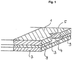
- FIG. 1 shows an enlarged detail in perspective view of a sample application zone in a particularly preferred embodiment of the test element according to the invention.
- the test element comprises a support (1) with a recess (5) which facilitates the penetration of a sample liquid from the sample application zone (4) into a capillary-active channel (3), in the present case by the support (1), an intermediate layer ( 9) and a cover (7) is formed.
- the channel (3) leads to the detection zone of the test element (not shown).
- the recess may, in addition to the shape shown, to any other, any shape that is useful for the purpose of the invention.
- the coating according to the invention can be present on the shaded surface areas of the carrier (1) of the cover (7) of the intermediate layer (9) and on the underside of the cover (7), not shown.
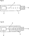
- FIGS. 2a and b show by way of example possible application ranges of the coating according to the invention on a test element.
- the test element contains a carrier (1), a detection zone (2) and a sample application zone (4) which is connected to the detection zone (2) via a channel (3).
- the coating according to the invention (hatched) can, as in Fig. 2a shown - only present on a limited part of the support in the area of the sample application zone (4) or - as in Fig. 2b shown - extend over much of the test element.
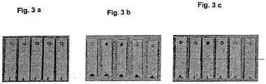
- FIG. 3 is a comparison of the blood uptake properties of test elements with lotus effect surface ( Fig. 3a ), an untreated surface ( Fig. 3b ) and a Teflon-coated surface ( Fig. 3c ).
- the test elements have a sample application zone with a recess (below) which communicates with a detection zone via a capillary channel.
- test element was coated on the outside with a spray (lotus effect spray, Creavis), which is coated with the surface of the carrier film with hydrophobic nanoparticles, so that a hydrophobic structure is formed with protrusions.
- a spray lotus effect spray, Creavis
- Creavis coated with the surface of the carrier film with hydrophobic nanoparticles, so that a hydrophobic structure is formed with protrusions.
Landscapes
- Chemical & Material Sciences (AREA)
- Health & Medical Sciences (AREA)
- Dispersion Chemistry (AREA)
- Analytical Chemistry (AREA)
- General Health & Medical Sciences (AREA)
- Hematology (AREA)
- Clinical Laboratory Science (AREA)
- Chemical Kinetics & Catalysis (AREA)
- Investigating Or Analysing Biological Materials (AREA)
- Automatic Analysis And Handling Materials Therefor (AREA)
- Investigating Or Analysing Materials By The Use Of Chemical Reactions (AREA)
Description
- Die Erfindung betrifft beschichtete Testelemente, insbesondere Testelemente mit einem Kapillarspalt, die zumindest in dem den Kapillarspalt umgebenden Bereich eine hydrophobe strukturierte Beschichtung aufweisen.
- Testelemente für diagnostische Vorrichtungen, z.B. Blutzuckermesssysteme, werden vielfach von den Patienten selbst angewendet. Die Anwendung umfasst im Allgemeinen das Aufbringen einer Probe von Körperflüssigkeit, z.B. Blut, auf das Testelement, das Einführen des Testelements in eine Messvorrichtung und die Bestimmung eines Analyten aus der Körperflüssigkeit in der Messvorrichtung. Dabei war bisher der Verbleib von überschüssigem Probenmaterial, z.B. Blut, alleine dem Anwender überlassen. Bei Entsorgung des Testelements konnte dieses Probenmaterial je nach Entsorgungsort eine ernste Verschmutzungsgefahr und ein Hygieneproblem darstellen. Besonders relevant war dieses Problem bei Teststreifen mit Kapillarspalt, bei denen es oftmals zum Anhaften von Blut an der Außenseite der Kapillare kam.
- Der aktuelle Trend bei Blutzuckermesssystemen läuft auf eine zunehmende Integration der Handhabungsschritte und Systemeinzelteile hinaus. Dabei werden die Testelemente oftmals in bzw. durch die Messvorrichtung gezogen. Auf dem Weg des Testelements durch die Vorrichtung stellt jedes außen am Testelement anhaftende Probenmaterial ein Verschmutzungsrisiko des Messgeräts dar. Insbesondere besteht dieses Verschmutzungsrisiko des Messgeräts bei der Remagazinierung der Teststreifen. Hierbei werden Teststreifen, nachdem eine Probenaufgabe an einem Teststreifen erfolgt ist, innerhalb des Messgerätes transportiert. Ein Verschmutzungsrisiko besteht folglich zum einen während des Testelementtransports, nachdem eine Probe aufgegeben wurde, und zum anderen durch die Lagerung bereits verwendeter Testelemente innerhalb des Magazins. Hierbei besteht das Risiko, dass getrocknetes Blut vom Testelement abfällt, sodass eine Verschmutzung des Magazingehäuses bzw. eine Kontamination noch zur Verwendung vorgesehener Testelemente bedingt wird.
- Ein weiteres Problem ist, dass an der Außenseite von Testelementen angetrocknetes Probenmaterial abkrümeln und Geräteteile, Optik und die Umwelt kontaminieren kann.
-
WO 97/46887 WO 99/29429 - Es besteht deshalb ein Bedarf nach Testelementen und Testverfahren, bei denen eine Verschmutzung durch Probenmaterial, insbesondere bei der Remagazinierung, möglichst weitgehend vermieden werden kann. Versuche zur hydrophoben Beschichtung von Testelementen mit Tensiden und Wachsen, mit Teflonfolien und Spray sowie mit Silikon-haltigen Hydrophobisierungsmitteln erwiesen sich jedoch weitgehend als erfolglos.
- Bei Beschichtung von Testelementen mit hydrophoben strukturierten Oberflächen, welche auch unter dem Namen Lotus-Oberflächen bekannt sind, wurde überraschenderweise gefunden, dass eine Verschmutzung mit Probenmaterial, insbesondere mit Blut, weitestgehend ausgeschlossen werden kann. Insbesondere bei Testelementen, die eine Kanalöffnung bzw. einen Spalt zur Aufnahme und zum Transport von Probenmaterial aufweisen, konnte gezeigt werden, dass durch Lotus-Oberflächen eine ausschließliche Benetzung der Kanalöffnung bzw. des Spaltes erzielt wird
- Darüber hinaus hat die Beschichtung mit Lotus-Oberflächen den Vorteil, dass eine genaue Dosierung und somit eine Reduktion des Probenvolumens möglich ist, wie es im Folgenden ausführlich dargelegt wird.
- Insbesondere eignet sich die Lotus-Oberflächen-Beschichtung für Testelemente mit hydrophiler Kapillarstruktur, da bei derartigen Testelementen mit einer Verschmutzung des Randbereiches der Testelemente und somit des Messgerätes gerechnet werden muss. Bei derartigen Systemen ragen die Testelemente während der Blutaufgabe zunächst aus dem Gerät heraus. Das Blut wird von dem Benutzer auf dem aus dem Gerät hervorstehenden Ende des Testelements, an dem die Öffnung der Kapillare angeordnet ist, aufgetragen. Bei Beschichtung des Testelements mit einer Lotus-Oberfläche, zumindest im Bereich der Öffnung, wird überschüssiges Blut entweder in die Kapillare eingesaugt oder tropft am Testelementrand ab, sodass ausschließlich der Kapillarspalt des Testelements benetzt wird, wobei an dem den Kapillarspalt umgebenden Bereich des Testelements kein Blut anhaftet.
- Ein Gegenstand der Erfindung ist somit ein analytisches Testelement zur Bestimmung eines Analyten in einer Flüssigkeit entsprechend Anspruch 1. Bei hydrophob strukturierten Oberflächen bzw. Lotus-Effekt-Oberflächen handelt es sich um selbstreinigende Oberflächen, die Erhebungen aufweisen, wobei der mittlere Abstand zwischen Erhebungen vorzugsweise im Bereich von 50 nm bis 200 µm, besonders bevorzugt im Bereich von 50 nm bis 10 µm und die mittlere Höhe der Erhebungen vorzugsweise im Bereich von 50 nm bis 100 µm, besonders bevorzugt im Bereich von 50 nm bis 10 um, liegt. Weiterhin zeichnen sich Lotus-Effekt-Oberflächen vorzugsweise durch eine Oberflächenenergie von weniger als vorzugsweise 20 mN/m sowie erfindungsgemäß durch einen Kontaktwinkel von ≥ 120° und bis zu 160° gegenüber wässrigen Systemen auf. Zumindest die Erhebungen bestehen aus hydrophoben Materialen, beispielsweise Nanopartikeln mit hydrophoben Eigenschaften. Bevorzugte Beispiele für Oberflächen mit Lotus-Effekt sind in
EP-B-0 772 514 ,EP-B-0 933 388 ,EP-A-1 018 531 ,EP-A-1 040 874 ,EP-B-1 171 529 ,EP-A-1 249 280 undEP-A-1 249 467 beschrieben. Strukturierte hydrophobe Oberflächen mit Lotus-Effekt können, wie in den oben genannten Dokumenten beschrieben, durch viele verschiedene Methoden erzeugt werden, z.B. durch Beschichten, Tränken, Sprühen, Koextrudieren oder durch Spritzguss. Bevorzugt ist das Aufsprühen einer Suspension von hydrophoben Nanopartikein. - Besonders bevorzugt ist ein Verfahren, welches eine Fixierung der hydrophoben strukturierten Beschichtung auf der Oberfläche des Testelements beinhaltet. Dabei wird vorzugsweise zunächst eine härtbare Substanz auf die zu beschichtenden Bereiche des Testelements aufgebracht, anschließend werden hydrophobe Partikel, mit günstigerweise zerklüfteten Strukturen, auf die zu beschichtenden Bereiche aufgebracht und danach werden die Partikel durch Härten fixiert, wie in
EP-A-1 249 280 beschrieben ist. Als härtbare Substanzen sind z.B. Lacke geeignet, die einfach oder/und mehrfach ungesättigte Acrylate oder/und Methacrylate oder/und Polyurethane oder/und Silikonacrylate oder/und Urethanacrylate aufweisen. Die Lacke weisen vorzugsweise hydrophobe Eigenschaften auf. Die Partikel können selbst hydrophob, z.B. pulverförmige Polymere, insbesondere halogenierte Kohlenwasserstoffe wie etwa Polytetrafluorethylen, oder hydrophobierte Partikel, z.B. hydrophobe Aerosile, sein. Gegebenenfalls kann die Hydrophobisierung der Partikel auch nach dem Fixieren auf dem Träger erfolgen. Das Fixieren der Partikel erfolgt durch Härten, beispielsweise durch thermische oder chemische Energie oder/und durch Lichtenergie. Eine durch ein solches mehrstufiges Verfahren aufgebrachte hydrophobe Schicht ist besonders stabil gegen Abrieb und mechanische Belastungen. - Durch Bereitstellung eines Testelements, das eine Lotus-Effekt-Oberfläche in einem Bereich um die Aufgabezone und insbesondere um eine Kanalöffnung bzw. einen Spalt im Bereich der Aufgabezone aufweist, wird eine erleichterte Dosierung der Probenflüssigkeit ermöglicht, da die Probenflüssigkeit automatisch zur Kanalöffnung hingeleitet und ein Anhaften an die Kanalöffnung umgebenden Bereiche des Testelements verhindert wird. Dies ist insbesondere für Diabetespatienten, bei denen es sich oft um ältere oder sehbehinderte Personen handelt, von besonderem Interesse.
- Aufgrund der exakten Dosierbarkeit durch die hydrophobe strukturierte Oberfläche ist es weiterhin möglich, das Probenvolumen zu reduzieren, sodass eine schmerzarme Blutentnahme von nur noch sehr geringen Blutmengen ermöglicht wird. Darüber hinaus zeigt sich, dass insbesondere bei Remagazinierung von Testelementen eine hydrophobe Beschichtung der Testelemente vorteilhaft ist. Bei einer derartigen Remagazinierung wird das Testelement, das zunächst aus einem gegebenenfalls in die Messvorrichtung integrierten Magazin zur Probenaufgabe, z.B. zur Aufgabe von Blut, hinausgeschoben wird, anschließend wieder in dieses zurückgezogen. Bei erfindungsgemäßer Beschichtung des Testelements zeigt sich, dass eine Verschmutzung der Außenseite nicht zu befürchten ist.
- Das erfindungsgemäß beschichtete analytische Testelement besitzt eine Kanalöffnung bzw. einen Spalt im Bereich der Aufgabezone, wobei die Oberfläche des Testelements zumindest um die Kanalöffnung herum eine hydrophobe Strukturierung aufweist. Gegebenenfalls kann die Oberfläche des Testelements, zumindest die Teile, die vom Träger sowie von eventuell vorhandenen Abdeckungen oder Zwischenschichten gebildet werden, vollständig mit einer hydrophob strukturierten Beschichtung belegt sein. Der Kanal ist vorzugsweise ein Kapillarkanal bzw. Kapillarspalt, d.h. ein zum kapillaren Flüssigkeitstransport zur Nachweiszone des Testelements befähigter Kanal bzw. Spalt, der neben einer Öffnung in der Aufgabezone an seinem anderen Ende gegebenenfalls eine Entlüftungsöffnung besitzen kann. Der Kanal weist in seinem Inneren vorzugsweise zumindest teilweise eine hydrophile oder hydrophil beschichtete Oberfläche auf, z.B. eine metallische oder oxidische Oberfläche.
- Der Kanal- oder Spaltquerschnitt kann grundsätzlich beliebig sein. Vorzugsweise hat der Kanal bzw. Spalt einen im Wesentlichen rechteckigen Querschnitt, dessen Dimensionen durch die physikalischen Grenzen der Kapillaraktivität vorgegeben sind. Die Höhe des Kanals bzw. Spalts liegt beispielsweise für wässrige Probenflüssigkeiten in der Größenordnung von 10 bis 500 µm, bevorzugt zwischen 20 und 300 µm. Je nach gewünschtem Kanal- bzw. Spaltvolumen kann die Breite dann mehrere mm, bevorzugt 1 bis 10 mm, besonders bevorzugt 1 bis 3 mm, und die Länge bis zu einigen cm, bevorzugt 0.5 bis 5 cm, ganz bevorzugt 1 bis 3 cm, betragen.
- Vorzugsweise weist die Kante des Testelements, die die Probenaufgabezone bildet, eine Aussparung im Bereich der den Kanal bzw. Spalt bildenden Fläche auf, um den Eintritt der Probenflüssigkeit in den Kanal zu erleichtern. Die Dimension der Aussparung, z.B. deren Breite, wird vorzugsweise so gewählt, dass der Durchmesser des Tropfens der Probenflüssigkeit, der auf das Testelement aufgebracht wird, geringfügig größer ist als die gewählte Dimension der Aussparung. So hat sich für ein Tropfenvolumen von 3 µl eine Breite der Aussparung von etwa 1 mm als geeignet erwiesen. Die durch die Aussparung freiliegende Fläche weist - ebenso wie der Kanal oder Spalt selbst - vorzugsweise eine hydrophile oder hydrophil beschichtete Oberfläche auf.
- Desweiteren enthält das Testelement einen Teil oder alle der zur Bestimmung des Analyten notwendigen Reagenzien und gegebenenfalls Hilfsstoffe. Diese Reagenzien umfassen beispielsweise Enzyme, Enzymsubstrate, Indikatoren, Puffersalze, inerte Füllstoffe und dergleichen. Die Reagenzien sind vorzugsweise im Bereich der Nachweiszone enthalten. Die Nachweiszone kann aus einem oder mehreren Bereichen aufgebaut sein und enthält üblicherweise saugfähige Materialien, die mit den Reagenzien imprägniert sind. Beispiele für saugfähige Materialien sind Vliese, Gewebe, Gewirke oder poröse Kunststoffmaterialien, die in Form von beispielsweise Schichten vorliegen können. Bevorzugte Materialien sind Papiere oder poröse Kunststoffmaterialien wie Membranen. Besonders bevorzugt enthält die Nachweiszone offene Filme, wie sie z.B. in
EP-B-0 016 387 beschrieben sind. Die Filme können aus einer oder mehreren Schichten bestehen und auf einem Träger des Testelements aufgebracht sein. - Die Nachweiszone kann außerdem über Bestandteile verfügen, die einen Ausschluss störender Probenanteile von der Nachweisreaktion erlauben und somit als Filter, beispielsweise für partikuläre Probenbestandteile wie Blutzellen, wirken. Geeignete Beispiele hierfür sind semipermeable Membranen oder Glasfaservliese, wie sie aus
EP-B-0 045 476 bekannt sind. - Die Bestimmung des Analyten in der Nachweiszone kann durch optische Methoden, z.B. durch visuelle oder photometrische Bestimmung, durch elektrochemische Methoden oder andere geeignete Nachweismethoden erfolgen.
- Das Testelement kann weiterhin Abdeckungen oder/und Zwischenschichten enthalten, die zusammen mit dem Träger und gegebenenfalls der Nachweiszone die Begrenzung des Probentransportkanals bzw. -spalts bilden. Die Abdeckungen und Zwischenschichten können in ihren Eigenschaften, wie z.B. Material und Beschichtung, gleich oder ähnlich dem inerten Träger sein. Besonders bevorzugt ist dabei auf der dem Kanal bzw.
- Spalt hinzugewandten Seite einer Abdeckung eine flexible inerte Folie angebracht, die über die gesamte Länge der Abdeckung reicht, den Kanal bzw. Spalt auf der gesamten Breite bedeckt und die, zumindest teilweise zwischen den sich gegenüber liegenden Flächen der Abeckung und des Nachweiselements, eingeschlossen ist, sodass der kapillare Flüssigkeitstransport an der Berührungsstelle von Nachweiszone und Abdeckung nicht abreißt.
- Besonders bevorzugt sind analytische Testelemente mit einem Kapillarkanal, wie sie etwa in
WO 99/29429 - Das erfindungsgemäß beschichtete Testelement ist vorzugsweise für die Aufnahme innerhalb eines Magazins vorgesehen, das ein oder mehrere Testelemente enthalten kann.
- Bevorzugt ist das Testelement für eine Remagazinierung vorgesehen, d.h. zur Aufnahme in einem Magazin, das gemeinsam gebrauchte und ungebrauchte Testelemente enthalten kann, wobei ein ungebrauchtes Testelement vor Gebrauch aus dem Magazin entnommen und nach Gebrauch wieder in das Magazin rückgeführt wird. Die Entnahme oder/und Rückführung kann manuell oder automatisch erfolgen.
- Das einzelne Testelement kann ein Wegwerf-Testelement oder ein mehrfach benutzbares Testelement kann. Das Magazin kann innerhalb einer Messvorrichtung angeordnet sein, die beispielsweise für einen optischen oder elektrochemischen Nachweis vorgesehen ist.
- Das Testelement kann zum Nachweis beliebiger Analyten in flüssigen Probenmaterialien, insbesondere Körperflüssigkeiten wie Blut, Speichel oder Urin eingesetzt werden. Besonders bevorzugt ist die Bestimmung von Glucose in Blut. Andere bevorzugte Beispiele für die Anwendung der Testelemente sind die Koagulationsmessung oder die Messung von HBA1C.
- Ein weiterer Gegenstand der vorliegenden Erfindung ist eine Messvorrichtung zur Bestimmung eines Analyten in einer Flüssigkeit, die ein erfindungsgemäß beschichtetes Testelement enthält. Die Messvorrichtung kann ein oder mehrere Magazine zur Aufnahme von einem oder mehreren Testelementen integriert enthalten. Bevorzugt ist eine Messvorrichtung mit remagazinierten Testelementen, wobei gebrauchte und ungebrauchte Testelemente gemeinsam in einem Magazin vorliegen können.
- Noch ein weiterer Gegenstand der vorliegenden Erfindung ist ein Verfahren zur Bestimmung eines Analyten in einer Flüssigkeit, umfassend
- Aufbringen einer Probenflüssigkeit auf ein erfindungsgemäß beschichtetes Testelement und
- qualitatives und/oder quantitatives Bestimmen des in der Probenflüssigkeit vorhandenen Analyten.
- Vorzugsweise wird ein Volumen der Probenflüssigkeit, z.B. ein Volumen von 1 bis 10 µl, auf das Testelement aufgebracht. Das Aufbringen erfolgt im Bereich der Aufgabezone des Testelements, wobei die Oberfläche zumindest im Bereich um die Aufgabezone erfindungsgemäß hydrophob strukturiert beschichtet ist, um eine Verschmutzung durch überschüssiges oder/und ungenau aufgebrachtes Probenmaterial zu vermeiden.
- Die Bestimmung des Analyten erfolgt vorzugsweise in einer integrierten Messvorrichtung, wobei das Testelement von einer ersten Position in der Vorrichtung, z.B. in einem ersten Magazin, zu einer zweiten Position, z.B. einer Position zur Probenaufgabe, dann zu einer dritten Position, z.B. einer Position zur Bestimmung des Analyten und dann aus der Vorrichtung hinaus oder zu einer vierten Position, z.B. im ersten oder einem anderen Magazin, transportiert wird. Die Vorrichtung kann ein oder mehrere Magazine enthalten, die jeweils zur Aufnahme von einem oder mehreren Testelementen vorgesehen sind. Besonders bevorzugt ist eine Vorrichtung mit einem Magazin, in dem gebrauchte und ungebrauchte Testelemente gemeinsam vorliegen.
- Bevorzugte Ausführungsformen der vorliegenden Erfindungen werden durch die beigefügten Figuren und Beispiele erläutert:
Figur 1 zeigt eine Detailvergrößerung in perspektivischer Ansicht einer Probenaufgabezone in einer besonders bevorzugten Ausführungsform des erfindungsgemäßen Testelements. Das Testelement enthält einen Träger (1) mit einer Aussparung (5), die das Eindringen einer Probenflüssigkeit von der Probenaufgabezone (4) in einen Kapillar-aktiven Kanal (3) erleichtert, der im vorliegenden Fall vom Träger (1), einer Zwischenschicht (9) und einer Abdeckung (7) gebildet wird. Der Kanal (3) führt zur Nachweiszone des Testelements (nicht gezeigt). Die Aussparung kann neben der gezeigten Form auf jede andere, beliebige Form besitzen, die dem erfindungsgemäßen Zweck dienlich ist. - Die erfindungsgemäße Beschichtung kann auf den schraffiert gezeichneten Oberflächenbereichen des Trägers (1) der Abdeckung (7) der Zwischenschicht (9) sowie auf der nicht gezeigten Unterseite der Abdeckung (7) vorhanden sein.
- Die
Figuren 2a und b zeigen beispielhaft mögliche Applikationsbereiche der erfindungsgemäßen Beschichtung auf einem Testelement. Das Testelement enthält einen Träger (1), eine Nachweiszone (2) sowie eine Probenaufgabezone (4), die über einen Kanal (3) mit der Nachweiszone (2) in Verbindung steht. Die erfindungsgemäße Beschichtung (schraffiert gezeichnet) kann -wie inFig. 2a gezeigt - nur auf einem begrenzten Teil des Trägers im Bereich der Probenaufgabezone (4) vorliegen oder - wie inFig. 2b gezeigt - sich über einen Großteil des Testelements erstrecken. - In
Figur 3 ist ein Vergleich der Blutaufnahmeeigenschaften von Testelementen mit Lotus-Effekt-Oberfläche (Fig. 3a ), einer unbehandelten Oberfläche (Fig. 3b ) und einer Teflon-beschichteten Oberfläche (Fig. 3c ). Die Testelemente weisen eine Probenaufgabezone mit Aussparung (unten) auf, die über einen Kapillarkanal mit einer Nachweiszone in Verbindung steht. - Ein gemäß
WO 99/29429 Fig. 3a ). Dagegen wurden bei einem Standard-Testelement mit gewachster Außenseite (Fig. 3b ) sowie einem mit Teflonspray behandelten Testelement (Fig. 3c ) starke Verschmutzungen durch Blut im Bereich der Aufgabezone gefunden.
Claims (20)
- Analytisches Testelement zur Bestimmung eines Analyten in einer Flüssigkeit, umfassend- einen inerten Träger (1),- eine Aufgabezone für Probenmaterial (4),- eine Nachweiszone zur Bestimmung des Analyten (2), und- einen Kanal oder Spalt (3) zum Transport von Flüssigkeit von der Aufgabezone zur Nachweiszone,wobei das Testelement zumindest in einem Bereich um die Aufgabezone (4) eine hydrophobe strukturierte Oberfläche aufweist, dadurch gekennzeichnet,
dass die hydrophobe strukturierte Oberfläche einen Kontaktwinkel mit wässrigen Systemen ≥ 120° aufweist. - Testelement nach Anspruch 1,
dadurch gekennzeichnet,
dass der Kanal oder Spalt (3) im Bereich der Aufgabezone (4) eine Öffnung aufweist und die Oberfläche des Testelements zumindest um die Öffnung herum die hydrophobe strukturierte Oberfläche aufweist. - Testelement nach Anspruch 1 oder 2,
dadurch gekennzeichnet,
dass der Kanal oder Spalt (3) ein Kapillarkanal oder Kapillarspalt ist. - Testelement nach einem der Ansprüche 1 bis 3,
dadurch gekennzeichnet,
dass der Kanal oder Spalt (3) im Inneren zumindest teilweise eine hydrophile Oberfläche aufweist. - Testelement nach einem der Ansprüche 1 bis 4,
dadurch gekennzeichnet,
dass der mittlere Abstand zwischen Erhebungen auf der hydrophoben strukturierten Oberfläche im Bereich von 50 nm bis 200 µm und die mittlere Höhe der Erhebungen im Bereich von 50 nm bis 100 µm liegt. - Testelement nach einem der Ansprüche 1 bis 5,
dadurch gekennzeichnet,
dass die hydrophobe strukturierte Oberfläche eine Oberflächenenergie von ≤ 20 mN/m aufweist. - Testelement nach einem der Ansprüche 1 bis 6,
dadurch gekennzeichnet,
dass die hydrophobe strukturierte Oberfläche durch Aufsprühen einer Suspension von hydrophoben Nanopartikeln erhältlich ist. - Testelement nach einem der Ansprüche 1 bis 7,
dadurch gekennzeichnet,
dass die hydrophobe strukturierte Oberfläche auf dem Testelement fixiert ist. - Testelement nach Anspruch 8,
dadurch gekennzeichnet,
dass die hydrophobe strukturierte Oberfläche durch Aufbringen einer härtbaren Substanz auf die zu beschichtenden Bereiche des Testelements, Aufbringen von hydrophoben, hydrophobisierten oder hydrophobisierbaren Partikeln auf die zu beschichtenden Bereiche und Fixieren der Partikel durch Härten erhältlich ist. - Testelement nach einem der Ansprüche 1 bis 9 zur Bestimmung von Glucose in Blut.
- Verwendung des Testelements nach einem der Ansprüche 1 bis 10, zur Aufnahme innerhalb eines Magazins.
- Verwendung des Testelements nach Anspruch 11 in einem Magazin, welches für die gemeinsame Aufnahme von gebrauchten und ungebrauchten Testelementen vorgesehen ist.
- Verwendung eines Testelements nach Anspruch 11 oder 12 in einem Magazin, welches innerhalb einer Messvorrichtung angeordnet ist.
- Verwendung des Testelements nach Anspruch 13, wobei die Messvorrichtung eine optische oder elektronische Messvorrichtung ist.
- Magazin für die Aufnahme von Testelementen zur Bestimmung eines Analyten in einer Flüssigkeit, umfassend mindestens ein Testelement nach einem der Ansprüche 1 bis 10.
- Magazin nach Anspruch 15,
dadurch gekennzeichnet,
dass es für die gemeinsame Aufnahme von gebrauchten und ungebrauchten Testelementen vorgesehen ist. - Messvorrichtung zur Bestimmung eines Analyten in einer Flüssigkeit,
dadurch gekennzeichnet,
dass sie mindestens ein Testelement nach einem der Ansprüche 1 bis 10 enthält. - Messvorrichtung nach Anspruch 17,
dadurch gekennzeichnet,
dass sie mindestens ein Magazin zur Aufnahme von einem oder mehreren der Testelemente enthält. - Messvorrichtung nach Anspruch 18,
dadurch gekennzeichnet,
dass das Magazin für die gemeinsame Aufnahme von gebrauchten und ungebrauchten Testelementen vorgesehen ist. - Verfahren zur Bestimmung eines Analyten in einer Flüssigkeit, umfassend- Aufbringen einer Probenflüssigkeit auf ein Testelement nach einem der Ansprüche 1 bis 10, und- qualitatives oder/und quantitatives Bestimmen des in der Probenflüssigkeit vorhandenen Analyten.
Applications Claiming Priority (2)
| Application Number | Priority Date | Filing Date | Title |
|---|---|---|---|
| DE10356752A DE10356752A1 (de) | 2003-12-04 | 2003-12-04 | Beschichtete Testelemente |
| PCT/EP2004/013782 WO2005054845A1 (de) | 2003-12-04 | 2004-12-03 | Beschichtete testelemente |
Publications (2)
| Publication Number | Publication Date |
|---|---|
| EP1690087A1 EP1690087A1 (de) | 2006-08-16 |
| EP1690087B1 true EP1690087B1 (de) | 2018-05-09 |
Family
ID=34625557
Family Applications (1)
| Application Number | Title | Priority Date | Filing Date |
|---|---|---|---|
| EP04803503.4A Expired - Lifetime EP1690087B1 (de) | 2003-12-04 | 2004-12-03 | Beschichtete testelemente |
Country Status (6)
| Country | Link |
|---|---|
| US (1) | US8163560B2 (de) |
| EP (1) | EP1690087B1 (de) |
| JP (1) | JP4520468B2 (de) |
| CA (1) | CA2549143C (de) |
| DE (1) | DE10356752A1 (de) |
| WO (1) | WO2005054845A1 (de) |
Families Citing this family (18)
| Publication number | Priority date | Publication date | Assignee | Title |
|---|---|---|---|---|
| JP4602311B2 (ja) | 2006-11-09 | 2010-12-22 | 株式会社日阪製作所 | 蒸気接触式加熱殺菌装置 |
| EP2011630A1 (de) * | 2007-07-03 | 2009-01-07 | F. Hoffmann-La Roche AG | Verfahren zur Herstellung eines Analyseelementes |
| EP2011629A1 (de) | 2007-07-03 | 2009-01-07 | F. Hoffman-la Roche AG | Verfahren zur Herstellung eines mikrofluiden Systems auf einer Polymeroberfläche |
| KR101460837B1 (ko) * | 2007-10-31 | 2014-11-11 | 아크레이 가부시키가이샤 | 분석 용구 |
| JPWO2012081695A1 (ja) * | 2010-12-17 | 2014-05-22 | 株式会社堀場製作所 | 被検液分析用チップ |
| CN102507552B (zh) * | 2011-10-24 | 2013-06-12 | 北京市药品检验所 | 快速检测他达拉非或其衍生物的方法 |
| ES2816075T3 (es) * | 2015-08-06 | 2021-03-31 | Lia Diagnostics Inc | Pruebas dispersables en agua |
| US11040345B2 (en) * | 2016-03-30 | 2021-06-22 | Sharp Life Science (Eu) Limited | Microfluidic device |
| US11325103B2 (en) | 2016-07-15 | 2022-05-10 | Lia Diagnostics, Inc. | Temporary hydrophobic matrix material treatments, materials, kits, and methods |
| US11673134B2 (en) | 2017-06-06 | 2023-06-13 | Northwestern University | Trans-interfacial magnetic separation |
| US12533047B2 (en) | 2020-04-19 | 2026-01-27 | John J. Daniels | Mask-based diagnostic system using exhaled breath condensate |
| WO2021216386A1 (en) * | 2020-04-19 | 2021-10-28 | Daniels John J | Mask-based diagnostic system using exhaled breath condensate |
| US12369816B2 (en) | 2020-04-19 | 2025-07-29 | John J. Daniels | Mask-based diagnostic system using exhaled breath condensate |
| US12442726B2 (en) | 2020-04-19 | 2025-10-14 | John J. Daniels | Mask-based testing system for detecting biomarkers in exhaled breath condensate, aerosols and gases |
| US12031982B2 (en) | 2020-04-19 | 2024-07-09 | John J. Daniels | Using exhaled breath condensate for testing for a biomarker of COVID-19 |
| AU2021379053A1 (en) | 2020-11-12 | 2023-02-23 | F. Hoffmann-La Roche Ag | Method for manufacturing at least one electrode of an analyte sensor |
| CN113267618B (zh) * | 2021-07-20 | 2021-09-28 | 北京华益精点生物技术有限公司 | 一种生物传感器 |
| US20240347190A1 (en) | 2023-04-17 | 2024-10-17 | John J. Daniels | Mask-based diagnostic utilizing ai algorithms for improved patient outcomes |
Citations (3)
| Publication number | Priority date | Publication date | Assignee | Title |
|---|---|---|---|---|
| DE19944256A1 (de) * | 1999-09-15 | 2001-04-12 | Ernst Markart | Teststreifen und Meßgerät zu seiner Vermessung |
| DE19942928A1 (de) * | 1999-09-08 | 2001-04-12 | Ernst Markart | Teststreifen |
| EP1362551A1 (de) * | 2002-05-09 | 2003-11-19 | Lifescan, Inc. | Analysegerät mit minimalem Handhabungsaufwand |
Family Cites Families (37)
| Publication number | Priority date | Publication date | Assignee | Title |
|---|---|---|---|---|
| IT964886B (it) | 1971-08-24 | 1974-01-31 | Cabot Corp | Composizione in polvere per tecni di esecuzione di rivestimenti senza solvente |
| CA1129498A (en) | 1978-10-25 | 1982-08-10 | Richard L. Columbus | Structural configuration and method for transport of a liquid drop through an ingress aperture |
| DE2910134A1 (de) | 1979-03-15 | 1980-09-25 | Boehringer Mannheim Gmbh | Diagnostisches mittel zum nachweis von bestandteilen von koerperfluessigkeiten |
| US4301115A (en) | 1979-06-22 | 1981-11-17 | Miles Laboratories, Inc. | Test device resistant to cross contamination between reactant areas and process for making it |
| DE3029579C2 (de) | 1980-08-05 | 1985-12-12 | Boehringer Mannheim Gmbh, 6800 Mannheim | Verfahren und Mittel zur Abtrennung von Plasma oder Serum aus Vollblut |
| CA2062027C (en) * | 1991-03-04 | 1998-05-19 | William Aldrich | Liquid control system for diagnostic cartridges used in analytical instruments |
| GR1002549B (el) | 1992-05-12 | 1997-01-28 | Lifescan Inc. | Λωρις εξετασεως με μεταφορικο μεσο δια μεταφορα ρευστου. |
| EP0621478B1 (de) | 1993-04-20 | 2003-06-25 | Fuji Photo Film Co., Ltd. | Trockener analytischer Film-Chip |
| EP0772514B1 (de) | 1994-07-29 | 1998-12-23 | Wilhelm Barthlott | Selbstreinigende oberflächen von gegenständen sowie verfahren zur herstellung derselben |
| US6605471B1 (en) | 1996-05-30 | 2003-08-12 | Radiometer Medical A/S | Method and system for determining at least one parameter of at least one sample of a physiological liquid, a holder and a test device |
| CN1171966C (zh) | 1996-05-31 | 2004-10-20 | 东陶机器株式会社 | 防污性构件及防污涂层组合物 |
| JPH10136972A (ja) | 1996-11-11 | 1998-05-26 | Nissui Pharm Co Ltd | 試験用具 |
| US6040195A (en) | 1997-06-10 | 2000-03-21 | Home Diagnostics, Inc. | Diagnostic sanitary test strip |
| DE19753847A1 (de) * | 1997-12-04 | 1999-06-10 | Roche Diagnostics Gmbh | Analytisches Testelement mit Kapillarkanal |
| WO1999036481A1 (en) | 1998-01-16 | 1999-07-22 | Cabot Corporation | Powder coating composition |
| DE19803787A1 (de) | 1998-01-30 | 1999-08-05 | Creavis Tech & Innovation Gmbh | Strukturierte Oberflächen mit hydrophoben Eigenschaften |
| JP2000103882A (ja) | 1998-09-28 | 2000-04-11 | Dow Corning Asia Ltd | 表面処理されたポリシルメチレン成形体及びその表面処理方法 |
| JP2000146892A (ja) | 1998-11-11 | 2000-05-26 | Nec Corp | プレーナ型化学センサ素子とその製造方法 |
| DE19860139C1 (de) | 1998-12-24 | 2000-07-06 | Bayer Ag | Verfahren zur Herstellung einer ultraphoben Oberfläche auf der Basis von Nickelhydroxid, ultraphobe Oberfläche und ihre Verwendung |
| ATE314147T1 (de) | 1998-12-24 | 2006-01-15 | Sumitomo Bakelite Co | Behälter für immunoassays |
| DE19900494A1 (de) | 1999-01-08 | 2000-07-13 | Creavis Tech & Innovation Gmbh | Hydrophobierungsverfahren für polymere Substrate |
| DE19913601C1 (de) | 1999-03-25 | 2000-08-10 | Wilhelm Barthlott | Vorrichtung und Verfahren zum verlustfreien Transport von Flüssigkeiten |
| PL191143B1 (pl) | 1999-03-25 | 2006-03-31 | Wilhelm Barthlott | Sposób wytwarzania samoczyszczących powierzchni |
| CA2302720C (en) | 1999-03-29 | 2009-07-14 | Ed Geistlich Sohne Ag Fur Chemische Industrie | Anticoagulant/sterilizing compositions and methods |
| DE19914007A1 (de) | 1999-03-29 | 2000-10-05 | Creavis Tech & Innovation Gmbh | Strukturierte flüssigkeitsabweisende Oberflächen mit ortsdefinierten flüssigkeitsbenetzenden Teilbereichen |
| DE19917367A1 (de) | 1999-04-16 | 2000-10-19 | Inst Neue Mat Gemein Gmbh | Verfahren zur Herstellung von Überzügen auf Basis fluorhaltiger Kondensate |
| CN1169188C (zh) | 1999-04-29 | 2004-09-29 | 赛弗根生物系统股份有限公司 | 具有憎水覆层的气相质谱仪样品支架 |
| EP1144773B1 (de) | 1999-05-26 | 2006-09-13 | Basf Corporation | Metalldachschindelvorrat und verfahren zur herstellung davon |
| DE19952314C2 (de) | 1999-10-29 | 2002-06-20 | Abb Patent Gmbh | Sensor, insbesondere Sensor mit planarer wirksamer Sensorfläche |
| DE10062203A1 (de) | 2000-12-13 | 2002-06-20 | Creavis Tech & Innovation Gmbh | Verfahren zur Abformung von hydrophoben Polymeren zur Erzeugung von Oberflächen mit beständig wasser- und ölabweisenden Eigenschaften |
| EP1343587A2 (de) * | 2000-12-18 | 2003-09-17 | Institut Für Physikalische Hochtechnologie E.V. | Vorrichtung zur aufnahme und abgabe von flüssigen substanzen |
| DE10118352A1 (de) * | 2001-04-12 | 2002-10-17 | Creavis Tech & Innovation Gmbh | Selbstreinigende Oberflächen durch hydrophobe Strukturen und Verfahren zu deren Herstellung |
| DE10118351A1 (de) | 2001-04-12 | 2002-10-17 | Creavis Tech & Innovation Gmbh | Selbstreinigende Oberflächen durch hydrophobe Strukturen und Verfahren zu deren Herstellung |
| DE10134362A1 (de) | 2001-07-14 | 2003-01-30 | Creavis Tech & Innovation Gmbh | Strukturierte Oberflächen mit Lotus-Effekt |
| DE10134477A1 (de) | 2001-07-16 | 2003-02-06 | Creavis Tech & Innovation Gmbh | Selbstreinigende Oberflächen durch hydrophobe Strukturen und Verfahren zu deren Herstellung |
| DE10138036A1 (de) | 2001-08-03 | 2003-02-20 | Creavis Tech & Innovation Gmbh | Strukturierte Oberflächen mit Lotus-Effekt |
| DE10142802A1 (de) | 2001-08-31 | 2003-03-20 | Bosch Gmbh Robert | Verschmutzungssicherer Sensor |
-
2003
- 2003-12-04 DE DE10356752A patent/DE10356752A1/de not_active Ceased
-
2004
- 2004-12-03 EP EP04803503.4A patent/EP1690087B1/de not_active Expired - Lifetime
- 2004-12-03 US US10/581,409 patent/US8163560B2/en active Active
- 2004-12-03 JP JP2006541911A patent/JP4520468B2/ja not_active Expired - Fee Related
- 2004-12-03 WO PCT/EP2004/013782 patent/WO2005054845A1/de not_active Ceased
- 2004-12-03 CA CA2549143A patent/CA2549143C/en not_active Expired - Fee Related
Patent Citations (3)
| Publication number | Priority date | Publication date | Assignee | Title |
|---|---|---|---|---|
| DE19942928A1 (de) * | 1999-09-08 | 2001-04-12 | Ernst Markart | Teststreifen |
| DE19944256A1 (de) * | 1999-09-15 | 2001-04-12 | Ernst Markart | Teststreifen und Meßgerät zu seiner Vermessung |
| EP1362551A1 (de) * | 2002-05-09 | 2003-11-19 | Lifescan, Inc. | Analysegerät mit minimalem Handhabungsaufwand |
Also Published As
| Publication number | Publication date |
|---|---|
| JP4520468B2 (ja) | 2010-08-04 |
| CA2549143C (en) | 2012-04-17 |
| JP2007513345A (ja) | 2007-05-24 |
| US20070110613A1 (en) | 2007-05-17 |
| DE10356752A1 (de) | 2005-06-30 |
| WO2005054845A1 (de) | 2005-06-16 |
| US8163560B2 (en) | 2012-04-24 |
| EP1690087A1 (de) | 2006-08-16 |
| CA2549143A1 (en) | 2005-06-16 |
Similar Documents
| Publication | Publication Date | Title |
|---|---|---|
| WO2005054845A1 (de) | Beschichtete testelemente | |
| EP1789192B1 (de) | Analytisches testelement | |
| EP0949002B1 (de) | Verfahren zur Herstellung von analytischen Hilfsmitteln | |
| EP1035921B1 (de) | Analytisches testelement mit kapillarkanal | |
| DE69524324T2 (de) | Pipettierspitze | |
| EP2257784B1 (de) | Küvette zur optischen Untersuchung kleiner Flüssigkeitsmengen | |
| EP1035920A1 (de) | Kapillaraktives testelement mit träger und abdeckung | |
| WO1999030158A1 (de) | Analytisches testelement mit sich verjüngendem kapillarkanal | |
| DE3151291A1 (de) | Geraet zur analyse von biologischen fluiden | |
| EP3025780B1 (de) | Inkubationswanne | |
| EP1035919B1 (de) | Vorrichtung zum kapillaren flüssigkeitstransport | |
| EP1507589A1 (de) | Vorrichtung zur probennahme von flüssigen proben | |
| EP2194873B1 (de) | Diagnostisches einmalteil | |
| DE29822031U1 (de) | Vorrichtung zur Wischprobenahme und Probenverdünnung | |
| WO2020244864A1 (de) | Überführungssystem für proben, insbesondere zu analysierende proben | |
| DE102023121081A1 (de) | Mikrofluidischer Testträger | |
| DE102023121082A1 (de) | Reaktionskammereinheit und mikrofluidischer Testträger | |
| EP2693943A1 (de) | Analysesystem mit messvorrichtung und testelement | |
| DE102023121083A1 (de) | Fluidspeichernde Testträger-Kanalstruktur und mikrofluidischer Testträger | |
| DE69407886T2 (de) | Verfahren zur Vorbehandlung von diagnostischen Testelementen | |
| DE10112298B4 (de) | Verwendung eines Messkammeraufsatzes für mehrfach verwendbare Chemo- und Biosensoren | |
| DE102019007512A1 (de) | Mikrofluidische Vorrichtung zur Aufnahme von Flüssigkeiten und zugehöriges Verfahren | |
| DE20121774U1 (de) | Probenaufnahmevorrichtung |
Legal Events
| Date | Code | Title | Description |
|---|---|---|---|
| PUAI | Public reference made under article 153(3) epc to a published international application that has entered the european phase |
Free format text: ORIGINAL CODE: 0009012 |
|
| 17P | Request for examination filed |
Effective date: 20060320 |
|
| AK | Designated contracting states |
Kind code of ref document: A1 Designated state(s): AT BE BG CH CY CZ DE DK EE ES FI FR GB GR HU IE IS IT LI LT LU MC NL PL PT RO SE SI SK TR |
|
| RIN1 | Information on inventor provided before grant (corrected) |
Inventor name: SCHMID, WILFRIED Inventor name: FRANK, MARTIN Inventor name: BABIC, BRANISLAV Inventor name: HOFERER, JUERGEN Inventor name: PACHL, RUDOLF |
|
| DAX | Request for extension of the european patent (deleted) | ||
| 17Q | First examination report despatched |
Effective date: 20130307 |
|
| RAP1 | Party data changed (applicant data changed or rights of an application transferred) |
Owner name: F. HOFFMANN-LA ROCHE AG Owner name: ROCHE DIABETES CARE GMBH |
|
| STAA | Information on the status of an ep patent application or granted ep patent |
Free format text: STATUS: EXAMINATION IS IN PROGRESS |
|
| GRAP | Despatch of communication of intention to grant a patent |
Free format text: ORIGINAL CODE: EPIDOSNIGR1 |
|
| STAA | Information on the status of an ep patent application or granted ep patent |
Free format text: STATUS: GRANT OF PATENT IS INTENDED |
|
| INTG | Intention to grant announced |
Effective date: 20171122 |
|
| GRAS | Grant fee paid |
Free format text: ORIGINAL CODE: EPIDOSNIGR3 |
|
| GRAA | (expected) grant |
Free format text: ORIGINAL CODE: 0009210 |
|
| STAA | Information on the status of an ep patent application or granted ep patent |
Free format text: STATUS: THE PATENT HAS BEEN GRANTED |
|
| AK | Designated contracting states |
Kind code of ref document: B1 Designated state(s): AT BE BG CH CY CZ DE DK EE ES FI FR GB GR HU IE IS IT LI LT LU MC NL PL PT RO SE SI SK TR |
|
| REG | Reference to a national code |
Ref country code: GB Ref legal event code: FG4D Free format text: NOT ENGLISH |
|
| REG | Reference to a national code |
Ref country code: CH Ref legal event code: EP Ref country code: AT Ref legal event code: REF Ref document number: 998043 Country of ref document: AT Kind code of ref document: T Effective date: 20180515 |
|
| REG | Reference to a national code |
Ref country code: DE Ref legal event code: R096 Ref document number: 502004015681 Country of ref document: DE Ref country code: IE Ref legal event code: FG4D Free format text: LANGUAGE OF EP DOCUMENT: GERMAN |
|
| REG | Reference to a national code |
Ref country code: NL Ref legal event code: MP Effective date: 20180509 |
|
| REG | Reference to a national code |
Ref country code: LT Ref legal event code: MG4D |
|
| PG25 | Lapsed in a contracting state [announced via postgrant information from national office to epo] |
Ref country code: ES Free format text: LAPSE BECAUSE OF FAILURE TO SUBMIT A TRANSLATION OF THE DESCRIPTION OR TO PAY THE FEE WITHIN THE PRESCRIBED TIME-LIMIT Effective date: 20180509 Ref country code: SE Free format text: LAPSE BECAUSE OF FAILURE TO SUBMIT A TRANSLATION OF THE DESCRIPTION OR TO PAY THE FEE WITHIN THE PRESCRIBED TIME-LIMIT Effective date: 20180509 Ref country code: BG Free format text: LAPSE BECAUSE OF FAILURE TO SUBMIT A TRANSLATION OF THE DESCRIPTION OR TO PAY THE FEE WITHIN THE PRESCRIBED TIME-LIMIT Effective date: 20180809 Ref country code: FI Free format text: LAPSE BECAUSE OF FAILURE TO SUBMIT A TRANSLATION OF THE DESCRIPTION OR TO PAY THE FEE WITHIN THE PRESCRIBED TIME-LIMIT Effective date: 20180509 Ref country code: LT Free format text: LAPSE BECAUSE OF FAILURE TO SUBMIT A TRANSLATION OF THE DESCRIPTION OR TO PAY THE FEE WITHIN THE PRESCRIBED TIME-LIMIT Effective date: 20180509 |
|
| PG25 | Lapsed in a contracting state [announced via postgrant information from national office to epo] |
Ref country code: NL Free format text: LAPSE BECAUSE OF FAILURE TO SUBMIT A TRANSLATION OF THE DESCRIPTION OR TO PAY THE FEE WITHIN THE PRESCRIBED TIME-LIMIT Effective date: 20180509 Ref country code: GR Free format text: LAPSE BECAUSE OF FAILURE TO SUBMIT A TRANSLATION OF THE DESCRIPTION OR TO PAY THE FEE WITHIN THE PRESCRIBED TIME-LIMIT Effective date: 20180810 |
|
| PG25 | Lapsed in a contracting state [announced via postgrant information from national office to epo] |
Ref country code: CZ Free format text: LAPSE BECAUSE OF FAILURE TO SUBMIT A TRANSLATION OF THE DESCRIPTION OR TO PAY THE FEE WITHIN THE PRESCRIBED TIME-LIMIT Effective date: 20180509 Ref country code: RO Free format text: LAPSE BECAUSE OF FAILURE TO SUBMIT A TRANSLATION OF THE DESCRIPTION OR TO PAY THE FEE WITHIN THE PRESCRIBED TIME-LIMIT Effective date: 20180509 Ref country code: DK Free format text: LAPSE BECAUSE OF FAILURE TO SUBMIT A TRANSLATION OF THE DESCRIPTION OR TO PAY THE FEE WITHIN THE PRESCRIBED TIME-LIMIT Effective date: 20180509 Ref country code: EE Free format text: LAPSE BECAUSE OF FAILURE TO SUBMIT A TRANSLATION OF THE DESCRIPTION OR TO PAY THE FEE WITHIN THE PRESCRIBED TIME-LIMIT Effective date: 20180509 Ref country code: PL Free format text: LAPSE BECAUSE OF FAILURE TO SUBMIT A TRANSLATION OF THE DESCRIPTION OR TO PAY THE FEE WITHIN THE PRESCRIBED TIME-LIMIT Effective date: 20180509 Ref country code: SK Free format text: LAPSE BECAUSE OF FAILURE TO SUBMIT A TRANSLATION OF THE DESCRIPTION OR TO PAY THE FEE WITHIN THE PRESCRIBED TIME-LIMIT Effective date: 20180509 |
|
| REG | Reference to a national code |
Ref country code: DE Ref legal event code: R097 Ref document number: 502004015681 Country of ref document: DE |
|
| PG25 | Lapsed in a contracting state [announced via postgrant information from national office to epo] |
Ref country code: IT Free format text: LAPSE BECAUSE OF FAILURE TO SUBMIT A TRANSLATION OF THE DESCRIPTION OR TO PAY THE FEE WITHIN THE PRESCRIBED TIME-LIMIT Effective date: 20180509 |
|
| PLBE | No opposition filed within time limit |
Free format text: ORIGINAL CODE: 0009261 |
|
| STAA | Information on the status of an ep patent application or granted ep patent |
Free format text: STATUS: NO OPPOSITION FILED WITHIN TIME LIMIT |
|
| 26N | No opposition filed |
Effective date: 20190212 |
|
| PG25 | Lapsed in a contracting state [announced via postgrant information from national office to epo] |
Ref country code: SI Free format text: LAPSE BECAUSE OF FAILURE TO SUBMIT A TRANSLATION OF THE DESCRIPTION OR TO PAY THE FEE WITHIN THE PRESCRIBED TIME-LIMIT Effective date: 20180509 |
|
| REG | Reference to a national code |
Ref country code: CH Ref legal event code: PL |
|
| GBPC | Gb: european patent ceased through non-payment of renewal fee |
Effective date: 20181203 |
|
| PG25 | Lapsed in a contracting state [announced via postgrant information from national office to epo] |
Ref country code: MC Free format text: LAPSE BECAUSE OF FAILURE TO SUBMIT A TRANSLATION OF THE DESCRIPTION OR TO PAY THE FEE WITHIN THE PRESCRIBED TIME-LIMIT Effective date: 20180509 Ref country code: LU Free format text: LAPSE BECAUSE OF NON-PAYMENT OF DUE FEES Effective date: 20181203 |
|
| REG | Reference to a national code |
Ref country code: IE Ref legal event code: MM4A |
|
| REG | Reference to a national code |
Ref country code: BE Ref legal event code: MM Effective date: 20181231 |
|
| PG25 | Lapsed in a contracting state [announced via postgrant information from national office to epo] |
Ref country code: IE Free format text: LAPSE BECAUSE OF NON-PAYMENT OF DUE FEES Effective date: 20181203 Ref country code: FR Free format text: LAPSE BECAUSE OF NON-PAYMENT OF DUE FEES Effective date: 20181231 |
|
| PG25 | Lapsed in a contracting state [announced via postgrant information from national office to epo] |
Ref country code: BE Free format text: LAPSE BECAUSE OF NON-PAYMENT OF DUE FEES Effective date: 20181231 |
|
| PG25 | Lapsed in a contracting state [announced via postgrant information from national office to epo] |
Ref country code: CH Free format text: LAPSE BECAUSE OF NON-PAYMENT OF DUE FEES Effective date: 20181231 Ref country code: GB Free format text: LAPSE BECAUSE OF NON-PAYMENT OF DUE FEES Effective date: 20181203 Ref country code: LI Free format text: LAPSE BECAUSE OF NON-PAYMENT OF DUE FEES Effective date: 20181231 |
|
| REG | Reference to a national code |
Ref country code: AT Ref legal event code: MM01 Ref document number: 998043 Country of ref document: AT Kind code of ref document: T Effective date: 20181203 |
|
| PG25 | Lapsed in a contracting state [announced via postgrant information from national office to epo] |
Ref country code: TR Free format text: LAPSE BECAUSE OF FAILURE TO SUBMIT A TRANSLATION OF THE DESCRIPTION OR TO PAY THE FEE WITHIN THE PRESCRIBED TIME-LIMIT Effective date: 20180509 |
|
| PG25 | Lapsed in a contracting state [announced via postgrant information from national office to epo] |
Ref country code: AT Free format text: LAPSE BECAUSE OF NON-PAYMENT OF DUE FEES Effective date: 20181203 |
|
| PG25 | Lapsed in a contracting state [announced via postgrant information from national office to epo] |
Ref country code: PT Free format text: LAPSE BECAUSE OF FAILURE TO SUBMIT A TRANSLATION OF THE DESCRIPTION OR TO PAY THE FEE WITHIN THE PRESCRIBED TIME-LIMIT Effective date: 20180509 |
|
| PG25 | Lapsed in a contracting state [announced via postgrant information from national office to epo] |
Ref country code: CY Free format text: LAPSE BECAUSE OF FAILURE TO SUBMIT A TRANSLATION OF THE DESCRIPTION OR TO PAY THE FEE WITHIN THE PRESCRIBED TIME-LIMIT Effective date: 20180509 Ref country code: HU Free format text: LAPSE BECAUSE OF FAILURE TO SUBMIT A TRANSLATION OF THE DESCRIPTION OR TO PAY THE FEE WITHIN THE PRESCRIBED TIME-LIMIT; INVALID AB INITIO Effective date: 20041203 |
|
| PG25 | Lapsed in a contracting state [announced via postgrant information from national office to epo] |
Ref country code: IS Free format text: LAPSE BECAUSE OF FAILURE TO SUBMIT A TRANSLATION OF THE DESCRIPTION OR TO PAY THE FEE WITHIN THE PRESCRIBED TIME-LIMIT Effective date: 20180909 |
|
| PGFP | Annual fee paid to national office [announced via postgrant information from national office to epo] |
Ref country code: DE Payment date: 20231121 Year of fee payment: 20 |
|
| REG | Reference to a national code |
Ref country code: DE Ref legal event code: R071 Ref document number: 502004015681 Country of ref document: DE |