EP1689504B1 - Brennstoffzellensystem mit einem ionenfilter - Google Patents
Brennstoffzellensystem mit einem ionenfilter Download PDFInfo
- Publication number
- EP1689504B1 EP1689504B1 EP04811877.2A EP04811877A EP1689504B1 EP 1689504 B1 EP1689504 B1 EP 1689504B1 EP 04811877 A EP04811877 A EP 04811877A EP 1689504 B1 EP1689504 B1 EP 1689504B1
- Authority
- EP
- European Patent Office
- Prior art keywords
- fuel cell
- fuel
- cell system
- filter
- ion
- Prior art date
- Legal status (The legal status is an assumption and is not a legal conclusion. Google has not performed a legal analysis and makes no representation as to the accuracy of the status listed.)
- Expired - Lifetime
Links
Images

Classifications
-
- H—ELECTRICITY
- H01—ELECTRIC ELEMENTS
- H01M—PROCESSES OR MEANS, e.g. BATTERIES, FOR THE DIRECT CONVERSION OF CHEMICAL ENERGY INTO ELECTRICAL ENERGY
- H01M8/00—Fuel cells; Manufacture thereof
- H01M8/04—Auxiliary arrangements, e.g. for control of pressure or for circulation of fluids
- H01M8/04082—Arrangements for control of reactant parameters, e.g. pressure or concentration
- H01M8/04186—Arrangements for control of reactant parameters, e.g. pressure or concentration of liquid-charged or electrolyte-charged reactants
-
- B—PERFORMING OPERATIONS; TRANSPORTING
- B01—PHYSICAL OR CHEMICAL PROCESSES OR APPARATUS IN GENERAL
- B01D—SEPARATION
- B01D15/00—Separating processes involving the treatment of liquids with solid sorbents; Apparatus therefor
- B01D15/02—Separating processes involving the treatment of liquids with solid sorbents; Apparatus therefor with moving adsorbents
-
- B—PERFORMING OPERATIONS; TRANSPORTING
- B01—PHYSICAL OR CHEMICAL PROCESSES OR APPARATUS IN GENERAL
- B01D—SEPARATION
- B01D24/00—Filters comprising loose filtering material, i.e. filtering material without any binder between the individual particles or fibres thereof
- B01D24/28—Filters comprising loose filtering material, i.e. filtering material without any binder between the individual particles or fibres thereof with the filter bed moving during the filtration
- B01D24/32—Rotation
-
- B—PERFORMING OPERATIONS; TRANSPORTING
- B01—PHYSICAL OR CHEMICAL PROCESSES OR APPARATUS IN GENERAL
- B01D—SEPARATION
- B01D29/00—Filters with filtering elements stationary during filtration, e.g. pressure or suction filters, not covered by groups B01D24/00 - B01D27/00; Filtering elements therefor
- B01D29/62—Regenerating the filter material in the filter
-
- H—ELECTRICITY
- H01—ELECTRIC ELEMENTS
- H01M—PROCESSES OR MEANS, e.g. BATTERIES, FOR THE DIRECT CONVERSION OF CHEMICAL ENERGY INTO ELECTRICAL ENERGY
- H01M8/00—Fuel cells; Manufacture thereof
- H01M8/02—Details
- H01M8/0289—Means for holding the electrolyte
-
- H—ELECTRICITY
- H01—ELECTRIC ELEMENTS
- H01M—PROCESSES OR MEANS, e.g. BATTERIES, FOR THE DIRECT CONVERSION OF CHEMICAL ENERGY INTO ELECTRICAL ENERGY
- H01M8/00—Fuel cells; Manufacture thereof
- H01M8/04—Auxiliary arrangements, e.g. for control of pressure or for circulation of fluids
-
- H—ELECTRICITY
- H01—ELECTRIC ELEMENTS
- H01M—PROCESSES OR MEANS, e.g. BATTERIES, FOR THE DIRECT CONVERSION OF CHEMICAL ENERGY INTO ELECTRICAL ENERGY
- H01M8/00—Fuel cells; Manufacture thereof
- H01M8/10—Fuel cells with solid electrolytes
- H01M8/1009—Fuel cells with solid electrolytes with one of the reactants being liquid, solid or liquid-charged
- H01M8/1011—Direct alcohol fuel cells [DAFC], e.g. direct methanol fuel cells [DMFC]
-
- H—ELECTRICITY
- H01—ELECTRIC ELEMENTS
- H01M—PROCESSES OR MEANS, e.g. BATTERIES, FOR THE DIRECT CONVERSION OF CHEMICAL ENERGY INTO ELECTRICAL ENERGY
- H01M8/00—Fuel cells; Manufacture thereof
- H01M8/10—Fuel cells with solid electrolytes
- H01M8/1016—Fuel cells with solid electrolytes characterised by the electrolyte material
- H01M8/1018—Polymeric electrolyte materials
- H01M8/102—Polymeric electrolyte materials characterised by the chemical structure of the main chain of the ion-conducting polymer
- H01M8/1023—Polymeric electrolyte materials characterised by the chemical structure of the main chain of the ion-conducting polymer having only carbon, e.g. polyarylenes, polystyrenes or polybutadiene-styrenes
-
- H—ELECTRICITY
- H01—ELECTRIC ELEMENTS
- H01M—PROCESSES OR MEANS, e.g. BATTERIES, FOR THE DIRECT CONVERSION OF CHEMICAL ENERGY INTO ELECTRICAL ENERGY
- H01M8/00—Fuel cells; Manufacture thereof
- H01M8/10—Fuel cells with solid electrolytes
- H01M8/1016—Fuel cells with solid electrolytes characterised by the electrolyte material
- H01M8/1018—Polymeric electrolyte materials
- H01M8/1039—Polymeric electrolyte materials halogenated, e.g. sulfonated polyvinylidene fluorides
-
- Y—GENERAL TAGGING OF NEW TECHNOLOGICAL DEVELOPMENTS; GENERAL TAGGING OF CROSS-SECTIONAL TECHNOLOGIES SPANNING OVER SEVERAL SECTIONS OF THE IPC; TECHNICAL SUBJECTS COVERED BY FORMER USPC CROSS-REFERENCE ART COLLECTIONS [XRACs] AND DIGESTS
- Y02—TECHNOLOGIES OR APPLICATIONS FOR MITIGATION OR ADAPTATION AGAINST CLIMATE CHANGE
- Y02E—REDUCTION OF GREENHOUSE GAS [GHG] EMISSIONS, RELATED TO ENERGY GENERATION, TRANSMISSION OR DISTRIBUTION
- Y02E60/00—Enabling technologies; Technologies with a potential or indirect contribution to GHG emissions mitigation
- Y02E60/30—Hydrogen technology
- Y02E60/50—Fuel cells
-
- Y—GENERAL TAGGING OF NEW TECHNOLOGICAL DEVELOPMENTS; GENERAL TAGGING OF CROSS-SECTIONAL TECHNOLOGIES SPANNING OVER SEVERAL SECTIONS OF THE IPC; TECHNICAL SUBJECTS COVERED BY FORMER USPC CROSS-REFERENCE ART COLLECTIONS [XRACs] AND DIGESTS
- Y02—TECHNOLOGIES OR APPLICATIONS FOR MITIGATION OR ADAPTATION AGAINST CLIMATE CHANGE
- Y02P—CLIMATE CHANGE MITIGATION TECHNOLOGIES IN THE PRODUCTION OR PROCESSING OF GOODS
- Y02P70/00—Climate change mitigation technologies in the production process for final industrial or consumer products
- Y02P70/50—Manufacturing or production processes characterised by the final manufactured product
Definitions
- This invention generally relates to fuel systems using fuel cells and fuel cartridges, and more particularly this invention relates to an ion filter incorporated into such systems.
- Fuel cells are devices that directly convert chemical energy of reactants, i.e ., fuel and oxidant, into direct current (DC) electricity.
- fuel cells are more efficient than conventional power generation, such as combustion of fossil fuel and more efficient than portable power storage, such as lithiumion batteries.
- fuel cell technologies include a variety of different fuel cells, such as alkali fuel cells, polymer electrolyte fuel cells, phosphoric acid fuel cells, molten carbonate fuel cells, solid oxide fuel cells and enzyme fuel cells.
- Today's more important fuel cells can be divided into three general categories, namely fuel cells utilizing compressed hydrogen (H 2 ) as fuel, proton exchange membrane (PEM) fuel cells that use methanol (CH 3 OH), sodium borohydride (NaBH 4 ), hydrocarbons (such as butane) or other fuels reformed into hydrogen fuel, and PEM fuel cells that use methanol (CH 3 OH) fuel directly (“direct methanol fuel cells” or DMFC).
- Compressed hydrogen is generally kept under high pressure, and is therefore difficult to handle.
- DMFC where methanol is reacted directly with oxidant in the fuel cell, is the simplest and potentially smallest fuel cell, and also has promising power application for consumer electronic devices.
- DMFC for relatively larger applications typically comprises a fan or compressor to supply an oxidant, typically air or oxygen, to the cathode electrode, a pump to supply a water/methanol mixture to the anode electrode and a membrane electrode assembly (MEA).
- the MEA typically includes a cathode, a PEM and an anode.
- the water/methanol liquid fuel mixture is supplied directly to the anode, and the oxidant is supplied to the cathode.
- the chemical-electrical reaction at each electrode and the overall reaction for a direct methanol fuel cell are described as follows:
- the external circuit may be any useful consumer electronic devices, such as mobile or cell phones, calculators, personal digital assistants and laptop computers, among others.
- DMFC is discussed in United States patent nos. 5,992,008 and 5,945,231 .
- the PEM is made from a polymer, such as Nafion® available from DuPont, which is a perfluorinated sulfonic acid polymer having a thickness in the range of about 0.05 mm to about 0.50 mm, or other suitable membranes.
- a polymer such as Nafion® available from DuPont, which is a perfluorinated sulfonic acid polymer having a thickness in the range of about 0.05 mm to about 0.50 mm, or other suitable membranes.
- the electrochemical cell reactions take place at a membrane electrode assembly typically comprised of an anode diffusion layer, comprised of a carbon paper support treated with a fluoropolymer, such as Teflon@ available from DuPont, an anode catalyst layer comprised of catalyst, such as platinum-ruthenium, and a proton conductor, such as Nafion® perfluorinated sulfonic acid polymer, the PEM, a cathode catalyst layer comprised of catalyst, such as platinum and a proton conductor and a cathode diffusion layer comprised of a carbon paper support treated with a fluoropolymer.
- an anode diffusion layer comprised of a carbon paper support treated with a fluoropolymer, such as Teflon@ available from DuPont
- an anode catalyst layer comprised of catalyst, such as platinum-ruthenium
- a proton conductor such as Nafion® perfluorinated sulfonic acid polymer
- the cell reaction for a sodium borohydride reformer fuel cell is as follows: NaBH 4 (aqueous) + 2H 2 O ⁇ (heat or catalyst) ⁇ 4(H 2 ) + (NaBO 2 ) (aqueous) H 2 ⁇ 2H + + 2e - (at the anode) 2(2H + + 2e - ) + O 2 ⁇ 2H 2 O (at the cathode)
- Suitable catalysts include platinum and ruthenium, among other metals.
- the hydrogen fuel produced from reforming sodium borohydride is reacted in the fuel cell with an oxidant, such as O 2 , to create electricity (or a flow of electrons) and water byproduct.
- Sodium borate (NaBO 2 ) byproduct is also produced by the reforming process.
- Sodium borohydride fuel cell is discussed in United States published patent application no. 2003/0082427 .
- Cations other than protons reduce the conductivity of the PEM.
- Especially damaging to the membrane conductivity are multivalent metal ions which tend to get trapped in the PEM.
- the conductivity is sufficiently reduced or when the level of trapped ions reaches a threshold level, the PEM has to be replaced or refurbished.
- United States patent no. US 6,265,093 B 1 discloses a direct methanol feed fuel cell system that includes a fuel filter located in front the MEA. This filter is a sieve-type filter that traps particles based on particle size to remove hydrocarbon impurities from the fuel.
- United States patent no. US 6,630,518 B1 discloses a polymer membrane that is irradiated and then sulfonated to link the sulfonic acid group to the membrane. The membrane is usable as the PEM in fuel cells and is usable as ion-exchange member or in ion-selective purification systems, among other uses.
- EP-A-1468857 discloses a zeolite - based filter which removes sulfur and any other odorizing 3 agent from the fuel.
- the present invention is directed to a fuel cell system comprising: a fuel cell having a polymer electrolyte membrane in a membrane electrode assembly, wherein during operation said polymer electrolyte membrane converts a fuel cell fuel to electricity; a fuel supply storing the fuel cell fuel to be transported to the fuel cell; and an ion filter comprising a filter medium, wherein said filter medium is made from a perfluorinated sulfonic acid polymer which is the same material as the material of the polymer electrolyte membrane in the membrane electrode assembly of the fuel cell, and at least one catalyst, wherein the filter medium is attractive to metal ions, and wherein the ion filter is in fluid communication with said fuel and located upstream from the polymer electrolyte membrane between the fuel supply and said fuel cell and removes metal ions from the fuel cell fuel.
- the ion filter can be positioned at any location in the fluidic system of a fuel cell.
- the fuel cell may comprise an inlet, an outlet and a medium made from a perfluorinated sulfonic acid polymer and disposed between the inlet and the outlet.
- the fuel exiting the filter contains less metal ion particles than fuel entering the filter.
- the perfluorinated sulfonic acid polymeric medium is substantially similar to the polymer exchange membrane in the membrane electrode assembly of the fuel cell.
- the filter can be connected to a fuel supply or to a fuel cell component.
- the filter may also have a housing that encases the filter medium, and the filter medium can be shredded or can be in the form of ingots to increase the surface area of the medium.
- the fuel supply for a fuel cell may comprise an outer casing containing fuel with a first amount of ions therein, and an ion filter supported by the casing.
- the ion filter is in fluid communication with fuel so that the fuel exiting the ion filter has a second amount of ions less than the first amount of ions.
- This ion filter is substantially similar to the ion filter described above.
- a perfluorinated sulfonic acid polymer filter medium is adapted to attract metal ions from fuel usable in a fuel cell and from liquid byproduct produced in the fuel cell.
- the filter medium is substantially similar to the polymer exchange membrane in the membrane electrode assembly of the fuel cell, and the filter medium is positioned within the fluidic flow path related to the fuel cell, e. g., the fuel cartridge, the mixing chamber and/or the byproduct chamber.
- the present invention is directed to a fuel supply, which stores fuel cell fuels such as methanol and water, methanol/water mixture, methanol/water mixtures of varying concentrations or pure methanol.
- Methanol is usable in many types of fuel cells, e.g ., DMFC, enzyme fuel cell, reformat fuel cell, among others.
- the fuel supply may contain other types of fuel cell fuels, such as ethanol or alcohols, chemicals that can be reformatted into hydrogen, or other chemicals that may improve the performance or efficiency of fuel cells.
- Fuels also include potassium hydroxide (KOH) electrolyte, which is usable with metal fuel cells or alkali fuel cells, and can be stored in fuel supplies.
- KOH potassium hydroxide
- fuel is in the form of fluid borne zinc particles immersed in a KOH electrolytic reaction solution, and the anodes within the cell cavities are particulate anodes formed of the zinc particles.
- KOH electrolytic solution is disclosed in United States published patent application no. 2003/0077493 , entitled “Method of Using Fuel Cell System Configured to Provide Power to One or more Loads,” published on April 24, 2003.
- Fuels also include a mixture of methanol, hydrogen peroxide and sulfuric acid, which flows past a catalyst formed on silicon chips to create a fuel cell reaction.
- Fuels also include aqueous sodium borohydride (NaBH 4 ) and water discussed above.
- Fuels further include hydrocarbon fuels, which include, but are not limited to, butane, kerosene, alcohol and natural gas, disclosed in United States published patent application no. 2003/0096150 , entitled “Liquid Hereto-Interface Fuel Cell Device,” published on May 22, 2003.
- Fuels also include liquid oxidants that react with fuels.
- the present invention is, therefore, not limited to any type of fuels, electrolytic solutions, oxidant solutions or liquids contained in the supply.
- fuel as used herein includes all fuels that can be reacted in fuel cells or in the fuel supply, and includes, but is not limited to, all of the above suitable fuels, electrolytic solutions, oxidant solutions, liquids, and/or chemicals and mixtures thereof.
- fuel supply includes, but is not limited to, disposable cartridges, refillable/reusable cartridges, containers, cartridges that reside inside the electronic device, removable cartridges, cartridges that are outside of the electronic device, fuel tanks, fuel refilling tanks, other containers that store fuel and the tubings connected to the fuel tanks and containers. While a cartridge is described below in conjunction with the exemplary embodiments of the present invention, it is noted that these embodiments are also applicable to other fuel supplies and the present invention is not limited to any particular type of fuel supplies.
- the fuel cell system possesses an ability to filter the fuel to significantly reduce the metal ion particles in the fuel.
- the present invention is directed to a fuel cell 10 for powering electronic device 11.
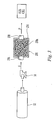
- FIG. 1 illustrates one embodiment of the present invention and the fuel cell system contains two sets of connecting lines.
- the first set of connecting lines comprises fluid, i.e ., liquid and gas, lines, which have arrows to show the direction of flow.
- the second set of connecting lines comprises electrical lines, which have darkened circles at the intersections to show electrical connectivity. While this embodiment is described with respect to direct methanol fuel cell, it is understood that this embodiment is suitable for any fuel cell.
- Cartridge 12 is connected to fuel cell 10, which powers electronic device 11.
- Cartridge 12 can be formed with or without an inner liner or bladder.
- Cartridges without liners and related components are disclosed in co-pending United States patent application serial no. 10/356,793 , entitled “Fuel Cartridge for Fuel Cells,” filed on January 31, 2003.
- Cartridges with inner liners or bladders are disclosed in co-pending United States patent application serial no. 10/629,004 , entitled “Fuel Cartridge with Flexible Liner,” filed on July 29, 2003.
- the fuel cell system shown in FIG. 1 is fully described in co-pending United States patent application entitled “Fuel Cell System including Information Storage Device and Control System,” filed on even date herewith.
- Electronic device 11 is typically larger than fuel cell 10 and usually houses the fuel cell. In FIG. 1 , electronic device 11 is shown schematically to surround fuel cell 10. It is also represented by a box drawn by broken lines and is powered by the electrical current produced by MEA 16. The electrical device can also be a charger that recharges batteries.
- valve 24 which preferably is a two-component valve.
- Valve component 24a is attached to the cartridge and valve component 24b is connected to pump 14.
- Each valve component is capable of forming a seal when the fuel cartridge is separated from the fuel cell.
- Two component valves are fully disclosed in co-pending patent application serial no. 10/629,006 entitled “Fuel Cartridge with Connecting Valve,” filed on July 29, 2003.
- valve component 24b may directly connect to pump 14 and provides a seal for pump 14, when the fuel cartridge is disconnected. Alternatively, valve component 24b may be attached to other fuel cell components.
- Pump 14 is connected to optional valve 252, which functions as a flow regulating device, and the flow rate through pump 14 and valve 252 can be measured with flow meter 254, such as a Venturi meter or other electronic flow meters.
- Fuel is then pumped into mixing chamber 250. From mixing chamber 250, fuel/water mixture is pump directly to MEA 16 to generate electricity to power electrical device 11.
- Liquid and gas byproducts e.g ., water and carbon dioxide, can be pumped or flowed under pressure from the carbon dioxide gas to byproduct chamber 256. The water byproduct is then transported back to mixing chamber 250.
- Mixing chamber 250 has relief valve 258 to vent the gas byproduct and excess water outside the fuel cell.
- Relief valves can be poppet-type valve disclosed in the '004 application.
- the water is mixed with fuel in mixing chamber 250 to achieve an optimal fuel concentration.
- Fuel concentration is measured by fuel concentration sensor 260, and these sensors are disclosed in United States patent publication nos. 2003/0131663 and 2003/0134162 and in United States patent nos. 6,254,748 and 6,306,285 .
- regulating valve 252 regulates the flow of fuel to MEA 16. Regulating valve 252 is fully disclosed in co-pending patent application entitled "Fuel Cell System including Information Storage Device and Control System.”
- the byproducts except for the water required for the fuel cell reaction, are transferred back to fuel cartridge 12 for disposal.
- Relief valve 258 can be disposed on the fuel cartridge to vent the gas byproduct to atmosphere.
- byproduct chamber 256 can be omitted and the byproducts are transported directly from MEA 16 to mixing chamber 250.
- chamber 250 can be divided into two portions as illustrated by the broken line in chamber 250.
- Chamber 250a is adapted to receive fuel from the fuel cartridge and chamber 250b is the byproducts.
- Each chamber 250a and 250b is individually connected directly to MEA 16 or to another mixing chamber upstream of the MEA.
- Each chamber 250a, 250b can be individually connected to a pump, e.g ., pump 262, to regulate the flow from each chamber to the MEA to obtain optimal fuel concentration.
- controller 18 is setup to control the flow of fuel through the fuel cell.
- Controller 18 can be positioned within fuel cell 10 or in electronic device 11.
- the controller can also be positioned on the fuel cartridge, or the functions of the controller can be performed by the central processing unit (CPU) or controller of the electronic device 11.
- Controller 18 can read information stored on information storage devices 23, 266, 268 and write information to these information storage devices.
- Controller 18 can also read electrically readable fuel gauge 264 to ascertain the amount of remaining fuel. Such gauge is disclosed in co-pending patent application serial no. 10/725,236 , entitled “Fuel Gages for Fuel Cartridges,” filed on even date herewith.
- Controller 18 can also be connected to two-component valve 24, so that the controller can control the opening and closing of valve 24.
- the controller can also read sensors, such as flow meter 254, fuel concentration sensor 260 and ion sensor 272.
- Controller 18 can also set the pumping rate of pump 14 or how wide regulating valve 252 should be opened to control the flow rate.
- the controller is also connected to optional pump 262, which pumps fuel or fuel mixture from mixing chamber 250 to the MEA, to control the flow rate.
- optional pump 262 which pumps fuel or fuel mixture from mixing chamber 250 to the MEA, to control the flow rate.
- another regulating valve similar to valve 252, is connected to pump 262 to control the flow rate.
- an ion filter is provided to fuel cell 10 and/or cartridge 12.
- Filter 270 comprises a Nafion® perfluorinated sulfonic acid polymer (available from DuPont). Since ion particles are known to permeate and reduces the effectiveness of Nafion® polymers used as the PEM in the MEA, when the filter material is made from the substantially same material as the PEM and the filter is located upstream of the MEA, the ion particles would be attracted to the filter and be removed from the fuel before the fuel reaches the MEA. Hence, the filter material is selected to be substantially the same as the PEM material. Filter material can also be made from ion exchange resins such as Amberlyst® from Rohm & Haas.
- the polymer material is shredded into discrete pieces or be made into ingots 270a that are packed together to form filter 270.
- Providing a filter material of discrete pieces increases the surface area of the filter material exposed to the fuel F so that the filter can be compact and effective.
- the filter material can be provided in a fine powder or the like.
- the discrete polymer pieces 270a are bound together in an optional binder. Suitable binders should be resistant to the fuel used.
- the filter material can be contained within an open mesh fuel-resistant grid such as the matrix disclosed in co-pending '004 patent application.
- the metal ions in the fuel are absorbed or attracted to the filter material within the filter via diffusion so that the fuel F' exiting the filter has a second amount of ions less than the first amount of ions in the entering fuel F. Diffusion allows the filter material to collect ions when fuel flows through the filter, while requiring a relatively small pressure drop across the filter. Filter 270 does not discriminate based on particle size, and therefore is a non-sieve filter.
- the density and permeability of the filter material in filter 270 determine the flow characteristics of the fuel F through the filter.
- the filter material is wetted before it is assembled into the cartridge so that it expands to between about 5% to about 25% of its initial volume. More preferably, the filter material is wetted to expand to about 15% of its initial volume.
- the filter material may include the one or more catalysts, such as platinum and/or ruthenium that are "unsupported," i.e ., without a base material. Again, the filter material can be shredded or provided in a fine powder and used as previously discussed.
- the polymeric filter material can also be extruded to form a textile mat including woven and nonwoven, which is the disposed in the fuel flow path.
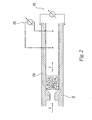
- Filter 270 when disposed in nozzle 22, as shown in FIG. 2 is downstream of the fuel supply and upstream of pump 14.
- pump 14 transports fuel from the fuel supply and through the filter under pressure.
- filter 270 is located downstream of fuel cartridge 12 and pump 14.
- Filter 270 may include discrete pieces 270a of filter material contained within housing 274.
- Housing 274 has inlet 276 and outlet 278.
- housing 274 is made from a fuel compatible material.
- the filter can also be located on the cartridge.
- filter 270 also acts as a flow regulator to slow down the flow of fuel when the shut-off valve opens.
- the filter and shut-off valves are fully disclosed in the co-pending '006 patent application.
- the filter can be positioned upstream or downstream from the shut-off valve.
- ion sensor 272 is provided to ascertain the effectiveness of the filter and to determine when the filter should be replaced.
- Ion sensor 272 is preferably located within fuel cell 10 as shown, or be disposed on the fuel cartridge.
- Ion sensor 272 is electrically connected with controller 18, and is readable by the controller.
- Ion sensor 272 applies an electrical field to the fuel, e.g ., across the tube carrying fuel or within the tube, as illustrated in FIG. 2 .
- This electrical field is either a constant voltage across the fuel or a constant current though the fuel.
- the electrical conductivity of the fuel depends on the concentration of ion particles in the fuel.
- the ion population is directly proportional to either the current flowing through the fuel if a constant voltage is applied across the fuel or the voltage across the fuel if a constant current is flowing through the fuel.
- a real-time ion measurement is compared to a base-line measurement of low ion fuel to determine whether the ion level is acceptable.
- a calibration curve or table can be drawn from data points representing low ion level, unacceptable ion level and one or more points therebetween. The real-time measurement can be compared to this calibration curve to ascertain the ion level during use.
- Controller 18 periodically reads this voltage or current and when the voltage or current reaches a predetermined level, the controller displays a message or other signal such as a visual or audible signal, to the user to change the ion filter, possibly at the next refill of the fuel supply.
Landscapes
- Chemical & Material Sciences (AREA)
- Chemical Kinetics & Catalysis (AREA)
- Sustainable Development (AREA)
- Life Sciences & Earth Sciences (AREA)
- Sustainable Energy (AREA)
- Manufacturing & Machinery (AREA)
- Engineering & Computer Science (AREA)
- Electrochemistry (AREA)
- General Chemical & Material Sciences (AREA)
- Crystallography & Structural Chemistry (AREA)
- Fuel Cell (AREA)
- Analytical Chemistry (AREA)
- Investigating Or Analyzing Non-Biological Materials By The Use Of Chemical Means (AREA)
Claims (18)
- Brennstoffzellensystem mit:einer Brennstoffzelle (10), die eine Polymerelektrolytmembran (PEM) in einer Membranelektrodenanordnung (16) aufweist, wobei die Polymerelektrolytmembran (PEM) während des Betriebs einen Brennstoffzellenbrennstoff in elektrischen Strom umwandelt;einer Brennstoffzufuhr (12), die den zu der Brennstoffzelle (10) zu transportierenden Brennstoffzellenbrennstoff speichert; undeinem Ionenfilter (270) mit einem Filtermedium, wobei das Filtermedium aus einem perfluorierten Schwefelsäurepolymer besteht, welches dasselbe Material ist wie das Material der Polymerelektrolytmembran (PEM) in der Membranelektrodenanordnung (16) der Brennstoffzelle (10), und wenigstens einem Katalysator, wobei das Filtermedium Metallionen anzieht, und wobei der Ionenfilter (270) in Fließverbindung mit dem Brennstoff steht und stromaufwärts der Polymerelektrolytmembran (PEM) zwischen der Brennstoffzufuhr (12) und der Brennstoffzelle (10) liegt und Metallionen aus dem Brennstoffzellenbrennstoff entfernt.
- Brennstoffzellensystem gemäß Anspruch 1, wobei sich der Ionenfilter (270) in einem Auslass (22) der Brennstoffzufuhr (12) befindet.
- Brennstoffzellensystem gemäß Anspruch 1, wobei sich der Ionenfilter (270) auf der Brennstoffzufuhr (12) befindet.
- Brennstoffzellensystem gemäß Anspruch 1, wobei der Ionenfilter (270) weiterhin einen Einlass (276) und einen Auslass (278) aufweist, und das Filtermedium zwischen dem Einlass (276) und dem Auslass (278) angeordnet ist.
- Brennstoffzellensystem gemäß Anspruch 4, weiterhin aufweisend ein Gehäuse (274), das das Filtermedium umschließt.
- Brennstoffzellensystem gemäß Anspruch 1, wobei der Ionenfilter (270) einzelne Teile (270a) des Filtermediums aufweist.
- Brennstoffzellensystem gemäß Anspruch 1, wobei das perfluorierte Schwefelsäurepolymermedium zerkleinert ist.
- Brennstoffzellensystem gemäß Anspruch 1, wobei das perfluorierte Schwefelsäurepolymermedium in der Form von Blöcken vorliegt.
- Brennstoffzellensystem gemäß Anspruch 1, wobei das perfluorierte Schwefelsäurepolymermedium aus einer Textilbahn besteht.
- Brennstoffzellensystem gemäß Anspruch 9, wobei die Textilbahn eine nicht gewebte Bahn ist.
- Brennstoffzellensystem gemäß Anspruch 9, wobei die Textilbahn eine gewebte Bahn ist.
- Brennstoffzellensystem gemäß Anspruch 1, wobei das perfluorierte Schwefelsäurepolymermedium in Pulverform vorliegt.
- Brennstoffzellensystem gemäß Anspruch 1, wobei das Filtermedium vor Gebrauch befeuchtet wird.
- Brennstoffzellensystem gemäß Anspruch 3, wobei die Brennstoffzufuhr (12) für die Brennstoffzelle (10) ein Außengehäuse umfasst, das den Brennstoffzellenbrennstoff enthält, und der Ionenfilter (270) von dem Gehäuse getragen wird.
- Brennstoffzellensystem gemäß Anspruch 1, wobei das Filtermedium innerhalb des Fluidfließwegs bezüglich der Brennstoffzelle (10) positioniert ist.
- Brennstoffzellensystem gemäß Anspruch 1, wobei der Ionenfilter (270) mit einem Ionensensor (272) versehen ist, um die elektrische Leitfähigkeit des Brennstoffs zu messen.
- Brennstoffzellensystem gemäß Anspruch 1, wobei der wenigstens eine Katalysator kein Basismaterial enthält.
- Brennstoffzellensystem gemäß Anspruch 1, wobei der wenigstens eine Katalysator Platin oder Ruthenium umfasst.
Applications Claiming Priority (2)
| Application Number | Priority Date | Filing Date | Title |
|---|---|---|---|
| US10/725,235 US7329348B2 (en) | 2003-12-01 | 2003-12-01 | Fuel cell system including an ion filter |
| PCT/US2004/039234 WO2005055336A2 (en) | 2003-12-01 | 2004-11-24 | Fuel cell system including an ion filter |
Publications (3)
| Publication Number | Publication Date |
|---|---|
| EP1689504A2 EP1689504A2 (de) | 2006-08-16 |
| EP1689504A4 EP1689504A4 (de) | 2008-03-19 |
| EP1689504B1 true EP1689504B1 (de) | 2013-05-01 |
Family
ID=34620259
Family Applications (1)
| Application Number | Title | Priority Date | Filing Date |
|---|---|---|---|
| EP04811877.2A Expired - Lifetime EP1689504B1 (de) | 2003-12-01 | 2004-11-24 | Brennstoffzellensystem mit einem ionenfilter |
Country Status (12)
| Country | Link |
|---|---|
| US (2) | US7329348B2 (de) |
| EP (1) | EP1689504B1 (de) |
| JP (2) | JP2007514281A (de) |
| KR (1) | KR101155849B1 (de) |
| CN (1) | CN1890008B (de) |
| AR (1) | AR047321A1 (de) |
| AU (1) | AU2004296030A1 (de) |
| BR (1) | BRPI0416893A (de) |
| CA (1) | CA2544407A1 (de) |
| ES (1) | ES2424776T3 (de) |
| TW (1) | TWI251369B (de) |
| WO (1) | WO2005055336A2 (de) |
Cited By (1)
| Publication number | Priority date | Publication date | Assignee | Title |
|---|---|---|---|---|
| DE102022101301B3 (de) | 2022-01-20 | 2023-07-20 | Schaeffler Technologies AG & Co. KG | Brennstoffzellensystem |
Families Citing this family (25)
| Publication number | Priority date | Publication date | Assignee | Title |
|---|---|---|---|---|
| US20060127711A1 (en) * | 2004-06-25 | 2006-06-15 | Ultracell Corporation, A California Corporation | Systems and methods for fuel cartridge distribution |
| WO2005004258A2 (en) * | 2003-06-27 | 2005-01-13 | Ultracell Corporation | Portable fuel cartridge for fuel cells |
| JP4569096B2 (ja) * | 2003-11-13 | 2010-10-27 | 日産自動車株式会社 | 燃料電池の冷却装置 |
| US7655331B2 (en) | 2003-12-01 | 2010-02-02 | Societe Bic | Fuel cell supply including information storage device and control system |
| US20050162122A1 (en) * | 2004-01-22 | 2005-07-28 | Dunn Glenn M. | Fuel cell power and management system, and technique for controlling and/or operating same |
| US7217470B2 (en) * | 2004-05-11 | 2007-05-15 | Societe Bic | Cartridge with fuel supply and membrane electrode assembly stack |
| US8246817B2 (en) * | 2004-06-10 | 2012-08-21 | Ford Motor Company | Deionization filter for fuel cell vehicle coolant |
| US7648792B2 (en) * | 2004-06-25 | 2010-01-19 | Ultracell Corporation | Disposable component on a fuel cartridge and for use with a portable fuel cell system |
| US7968250B2 (en) | 2004-06-25 | 2011-06-28 | Ultracell Corporation | Fuel cartridge connectivity |
| JP2007005051A (ja) * | 2005-06-22 | 2007-01-11 | Toshiba Corp | 燃料電池装置 |
| KR100707599B1 (ko) * | 2005-06-24 | 2007-04-13 | 삼성에스디아이 주식회사 | 연료혼합탱크 및 이를 구비한 연료전지장치 |
| JP2007149432A (ja) * | 2005-11-25 | 2007-06-14 | Fdk Corp | 直接メタノール型燃料電池 |
| US7922574B2 (en) | 2006-10-18 | 2011-04-12 | Aruze Gaming America, Inc. | Slot machine and playing method thereof |
| JP2009123442A (ja) * | 2007-11-13 | 2009-06-04 | Toshiba Corp | 燃料電池 |
| US8986404B2 (en) | 2009-11-03 | 2015-03-24 | Societe Bic | Gas generator with starter mechanism and catalyst shield |
| US8636826B2 (en) | 2009-11-03 | 2014-01-28 | Societe Bic | Hydrogen membrane separator |
| US8518254B2 (en) | 2009-12-02 | 2013-08-27 | Hyundai Motor Company | Coolant demineralizer for a fuel cell vehicle |
| US9757528B2 (en) | 2010-08-23 | 2017-09-12 | Darren Rubin | Nebulizer having different negative pressure threshold settings |
| CA2808836C (en) | 2010-08-23 | 2020-05-12 | Darren Rubin | Systems and methods of aerosol delivery with airflow regulation |
| WO2013080415A1 (ja) * | 2011-11-30 | 2013-06-06 | パナソニック株式会社 | 燃料電池システム |
| CN104591088A (zh) * | 2013-10-30 | 2015-05-06 | 扬光绿能股份有限公司 | 燃料处理装置及其氢气纯化装置 |
| US9876240B2 (en) | 2014-04-07 | 2018-01-23 | Intelligent Energy Limited | Multi-functional fuel cable |
| KR20160071873A (ko) | 2014-12-12 | 2016-06-22 | 현대자동차주식회사 | 연료 전지 차량용 이온필터 수명 감지 장치 |
| KR101684121B1 (ko) | 2015-05-29 | 2016-12-07 | 현대자동차주식회사 | 연료전지용 냉각수 이온필터 및 이의 제조 방법 |
| CN108232246B (zh) * | 2016-12-15 | 2020-03-10 | 中国科学院大连化学物理研究所 | 一种铝空气电池系统及其工作方法 |
Family Cites Families (17)
| Publication number | Priority date | Publication date | Assignee | Title |
|---|---|---|---|---|
| US64258A (en) * | 1867-04-30 | Anthony j | ||
| US175569A (en) * | 1876-04-04 | Improvement in smoke-preventives for railroad-cars | ||
| US4038365A (en) * | 1975-12-03 | 1977-07-26 | Basf Wyandotte Corporation | Removal of low level hardness impurities from brine feed to chlorine cells |
| US5773162A (en) * | 1993-10-12 | 1998-06-30 | California Institute Of Technology | Direct methanol feed fuel cell and system |
| FI107932B (fi) * | 1999-02-16 | 2001-10-31 | Mikael Paronen | Polymeerikalvo ja menetelmä sen valmistamiseksi |
| JP2001160408A (ja) * | 1999-12-01 | 2001-06-12 | Asahi Glass Co Ltd | 固体高分子電解質型燃料電池 |
| DE10032419A1 (de) * | 2000-07-04 | 2002-05-02 | Xcellsis Gmbh | Brennstoffzellensystem und Verfahren zum Betreiben des Brennstoffzellensystems |
| JP3404739B2 (ja) * | 2000-10-16 | 2003-05-12 | 株式会社豊田中央研究所 | フィルタ、並びにそれを用いた空気清浄機及びエアーコンディショナー |
| JP2002319427A (ja) * | 2001-04-19 | 2002-10-31 | Toshiba Corp | 燃料電池発電システム及び燃料電池発電方法 |
| US6503378B1 (en) * | 2001-04-23 | 2003-01-07 | Motorola, Inc. | Polymer electrolyte membrane and method of fabrication |
| US6921593B2 (en) | 2001-09-28 | 2005-07-26 | Hewlett-Packard Development Company, L.P. | Fuel additives for fuel cell |
| US6924054B2 (en) | 2001-10-29 | 2005-08-02 | Hewlett-Packard Development Company L.P. | Fuel supply for a fuel cell |
| US7122258B2 (en) * | 2001-10-31 | 2006-10-17 | Plug Power Inc. | Fuel cell air system and method |
| JP2003257464A (ja) | 2002-02-27 | 2003-09-12 | Nippei Toyama Corp | 燃料電池用の水素発生システム |
| JP3894002B2 (ja) | 2002-03-07 | 2007-03-14 | 株式会社豊田中央研究所 | 膜電極接合体並びにこれを備える燃料電池及び電気分解セル |
| US6630265B1 (en) * | 2002-08-13 | 2003-10-07 | Hoku Scientific, Inc. | Composite electrolyte for fuel cells |
| US7419060B2 (en) * | 2003-03-05 | 2008-09-02 | Hewlett-Packard Development Company, L.P. | Integrated fuel container and impurity removal cartridge |
-
2003
- 2003-12-01 US US10/725,235 patent/US7329348B2/en not_active Expired - Lifetime
-
2004
- 2004-11-09 TW TW093134172A patent/TWI251369B/zh not_active IP Right Cessation
- 2004-11-24 EP EP04811877.2A patent/EP1689504B1/de not_active Expired - Lifetime
- 2004-11-24 ES ES04811877T patent/ES2424776T3/es not_active Expired - Lifetime
- 2004-11-24 CN CN200480035616.7A patent/CN1890008B/zh not_active Expired - Fee Related
- 2004-11-24 KR KR1020067010426A patent/KR101155849B1/ko not_active Expired - Fee Related
- 2004-11-24 CA CA002544407A patent/CA2544407A1/en not_active Abandoned
- 2004-11-24 AU AU2004296030A patent/AU2004296030A1/en not_active Abandoned
- 2004-11-24 JP JP2006542620A patent/JP2007514281A/ja active Pending
- 2004-11-24 WO PCT/US2004/039234 patent/WO2005055336A2/en not_active Ceased
- 2004-11-24 BR BRPI0416893-3A patent/BRPI0416893A/pt not_active IP Right Cessation
- 2004-11-29 AR ARP040104434A patent/AR047321A1/es active IP Right Grant
-
2007
- 2007-12-14 US US11/956,538 patent/US7655147B2/en not_active Expired - Lifetime
-
2011
- 2011-03-03 JP JP2011046690A patent/JP5554265B2/ja not_active Expired - Fee Related
Cited By (1)
| Publication number | Priority date | Publication date | Assignee | Title |
|---|---|---|---|---|
| DE102022101301B3 (de) | 2022-01-20 | 2023-07-20 | Schaeffler Technologies AG & Co. KG | Brennstoffzellensystem |
Also Published As
| Publication number | Publication date |
|---|---|
| AR047321A1 (es) | 2006-01-18 |
| JP2007514281A (ja) | 2007-05-31 |
| TWI251369B (en) | 2006-03-11 |
| JP2011151031A (ja) | 2011-08-04 |
| CN1890008B (zh) | 2014-08-13 |
| AU2004296030A1 (en) | 2005-06-16 |
| WO2005055336A3 (en) | 2005-07-28 |
| CA2544407A1 (en) | 2005-06-16 |
| KR101155849B1 (ko) | 2012-07-03 |
| EP1689504A4 (de) | 2008-03-19 |
| BRPI0416893A (pt) | 2007-03-06 |
| EP1689504A2 (de) | 2006-08-16 |
| KR20060114700A (ko) | 2006-11-07 |
| US20050115882A1 (en) | 2005-06-02 |
| US20080118785A1 (en) | 2008-05-22 |
| ES2424776T3 (es) | 2013-10-08 |
| TW200525808A (en) | 2005-08-01 |
| US7329348B2 (en) | 2008-02-12 |
| CN1890008A (zh) | 2007-01-03 |
| WO2005055336A2 (en) | 2005-06-16 |
| US7655147B2 (en) | 2010-02-02 |
| JP5554265B2 (ja) | 2014-07-23 |
Similar Documents
| Publication | Publication Date | Title |
|---|---|---|
| US7655147B2 (en) | Method of removing ions from a fuel cell system | |
| US10090547B2 (en) | Fuel cell supply including information storage device and control system | |
| JP5518114B2 (ja) | 燃料サプライおよび膜電極組立体スタックを具備するカートリッジ |
Legal Events
| Date | Code | Title | Description |
|---|---|---|---|
| PUAI | Public reference made under article 153(3) epc to a published international application that has entered the european phase |
Free format text: ORIGINAL CODE: 0009012 |
|
| 17P | Request for examination filed |
Effective date: 20060503 |
|
| AK | Designated contracting states |
Kind code of ref document: A2 Designated state(s): AT BE BG CH CY CZ DE DK EE ES FI FR GB GR HU IE IS IT LI LU MC NL PL PT RO SE SI SK TR |
|
| DAX | Request for extension of the european patent (deleted) | ||
| A4 | Supplementary search report drawn up and despatched |
Effective date: 20080215 |
|
| RIC1 | Information provided on ipc code assigned before grant |
Ipc: H01M 8/10 20060101ALI20080211BHEP Ipc: H01M 8/02 20060101AFI20080211BHEP Ipc: H01M 8/04 20060101ALI20080211BHEP |
|
| 17Q | First examination report despatched |
Effective date: 20090710 |
|
| GRAP | Despatch of communication of intention to grant a patent |
Free format text: ORIGINAL CODE: EPIDOSNIGR1 |
|
| GRAS | Grant fee paid |
Free format text: ORIGINAL CODE: EPIDOSNIGR3 |
|
| GRAA | (expected) grant |
Free format text: ORIGINAL CODE: 0009210 |
|
| AK | Designated contracting states |
Kind code of ref document: B1 Designated state(s): AT BE BG CH CY CZ DE DK EE ES FI FR GB GR HU IE IS IT LI LU MC NL PL PT RO SE SI SK TR |
|
| REG | Reference to a national code |
Ref country code: GB Ref legal event code: FG4D |
|
| REG | Reference to a national code |
Ref country code: AT Ref legal event code: REF Ref document number: 610416 Country of ref document: AT Kind code of ref document: T Effective date: 20130515 Ref country code: CH Ref legal event code: EP |
|
| REG | Reference to a national code |
Ref country code: IE Ref legal event code: FG4D |
|
| REG | Reference to a national code |
Ref country code: DE Ref legal event code: R096 Ref document number: 602004042007 Country of ref document: DE Effective date: 20130627 |
|
| REG | Reference to a national code |
Ref country code: AT Ref legal event code: MK05 Ref document number: 610416 Country of ref document: AT Kind code of ref document: T Effective date: 20130501 |
|
| REG | Reference to a national code |
Ref country code: ES Ref legal event code: FG2A Ref document number: 2424776 Country of ref document: ES Kind code of ref document: T3 Effective date: 20131008 |
|
| REG | Reference to a national code |
Ref country code: NL Ref legal event code: VDEP Effective date: 20130501 |
|
| PG25 | Lapsed in a contracting state [announced via postgrant information from national office to epo] |
Ref country code: IS Free format text: LAPSE BECAUSE OF FAILURE TO SUBMIT A TRANSLATION OF THE DESCRIPTION OR TO PAY THE FEE WITHIN THE PRESCRIBED TIME-LIMIT Effective date: 20130901 Ref country code: SE Free format text: LAPSE BECAUSE OF FAILURE TO SUBMIT A TRANSLATION OF THE DESCRIPTION OR TO PAY THE FEE WITHIN THE PRESCRIBED TIME-LIMIT Effective date: 20130501 Ref country code: PT Free format text: LAPSE BECAUSE OF FAILURE TO SUBMIT A TRANSLATION OF THE DESCRIPTION OR TO PAY THE FEE WITHIN THE PRESCRIBED TIME-LIMIT Effective date: 20130902 Ref country code: FI Free format text: LAPSE BECAUSE OF FAILURE TO SUBMIT A TRANSLATION OF THE DESCRIPTION OR TO PAY THE FEE WITHIN THE PRESCRIBED TIME-LIMIT Effective date: 20130501 Ref country code: GR Free format text: LAPSE BECAUSE OF FAILURE TO SUBMIT A TRANSLATION OF THE DESCRIPTION OR TO PAY THE FEE WITHIN THE PRESCRIBED TIME-LIMIT Effective date: 20130802 Ref country code: SI Free format text: LAPSE BECAUSE OF FAILURE TO SUBMIT A TRANSLATION OF THE DESCRIPTION OR TO PAY THE FEE WITHIN THE PRESCRIBED TIME-LIMIT Effective date: 20130501 Ref country code: AT Free format text: LAPSE BECAUSE OF FAILURE TO SUBMIT A TRANSLATION OF THE DESCRIPTION OR TO PAY THE FEE WITHIN THE PRESCRIBED TIME-LIMIT Effective date: 20130501 |
|
| PG25 | Lapsed in a contracting state [announced via postgrant information from national office to epo] |
Ref country code: CY Free format text: LAPSE BECAUSE OF FAILURE TO SUBMIT A TRANSLATION OF THE DESCRIPTION OR TO PAY THE FEE WITHIN THE PRESCRIBED TIME-LIMIT Effective date: 20130501 Ref country code: PL Free format text: LAPSE BECAUSE OF FAILURE TO SUBMIT A TRANSLATION OF THE DESCRIPTION OR TO PAY THE FEE WITHIN THE PRESCRIBED TIME-LIMIT Effective date: 20130501 Ref country code: BG Free format text: LAPSE BECAUSE OF FAILURE TO SUBMIT A TRANSLATION OF THE DESCRIPTION OR TO PAY THE FEE WITHIN THE PRESCRIBED TIME-LIMIT Effective date: 20130801 |
|
| PG25 | Lapsed in a contracting state [announced via postgrant information from national office to epo] |
Ref country code: BE Free format text: LAPSE BECAUSE OF FAILURE TO SUBMIT A TRANSLATION OF THE DESCRIPTION OR TO PAY THE FEE WITHIN THE PRESCRIBED TIME-LIMIT Effective date: 20130501 Ref country code: SK Free format text: LAPSE BECAUSE OF FAILURE TO SUBMIT A TRANSLATION OF THE DESCRIPTION OR TO PAY THE FEE WITHIN THE PRESCRIBED TIME-LIMIT Effective date: 20130501 Ref country code: EE Free format text: LAPSE BECAUSE OF FAILURE TO SUBMIT A TRANSLATION OF THE DESCRIPTION OR TO PAY THE FEE WITHIN THE PRESCRIBED TIME-LIMIT Effective date: 20130501 Ref country code: CZ Free format text: LAPSE BECAUSE OF FAILURE TO SUBMIT A TRANSLATION OF THE DESCRIPTION OR TO PAY THE FEE WITHIN THE PRESCRIBED TIME-LIMIT Effective date: 20130501 Ref country code: DK Free format text: LAPSE BECAUSE OF FAILURE TO SUBMIT A TRANSLATION OF THE DESCRIPTION OR TO PAY THE FEE WITHIN THE PRESCRIBED TIME-LIMIT Effective date: 20130501 |
|
| PG25 | Lapsed in a contracting state [announced via postgrant information from national office to epo] |
Ref country code: RO Free format text: LAPSE BECAUSE OF FAILURE TO SUBMIT A TRANSLATION OF THE DESCRIPTION OR TO PAY THE FEE WITHIN THE PRESCRIBED TIME-LIMIT Effective date: 20130501 Ref country code: NL Free format text: LAPSE BECAUSE OF FAILURE TO SUBMIT A TRANSLATION OF THE DESCRIPTION OR TO PAY THE FEE WITHIN THE PRESCRIBED TIME-LIMIT Effective date: 20130501 Ref country code: IT Free format text: LAPSE BECAUSE OF FAILURE TO SUBMIT A TRANSLATION OF THE DESCRIPTION OR TO PAY THE FEE WITHIN THE PRESCRIBED TIME-LIMIT Effective date: 20130501 |
|
| PLBE | No opposition filed within time limit |
Free format text: ORIGINAL CODE: 0009261 |
|
| STAA | Information on the status of an ep patent application or granted ep patent |
Free format text: STATUS: NO OPPOSITION FILED WITHIN TIME LIMIT |
|
| 26N | No opposition filed |
Effective date: 20140204 |
|
| REG | Reference to a national code |
Ref country code: DE Ref legal event code: R097 Ref document number: 602004042007 Country of ref document: DE Effective date: 20140204 |
|
| REG | Reference to a national code |
Ref country code: CH Ref legal event code: PL |
|
| PG25 | Lapsed in a contracting state [announced via postgrant information from national office to epo] |
Ref country code: MC Free format text: LAPSE BECAUSE OF FAILURE TO SUBMIT A TRANSLATION OF THE DESCRIPTION OR TO PAY THE FEE WITHIN THE PRESCRIBED TIME-LIMIT Effective date: 20130501 Ref country code: LI Free format text: LAPSE BECAUSE OF NON-PAYMENT OF DUE FEES Effective date: 20131130 Ref country code: CH Free format text: LAPSE BECAUSE OF NON-PAYMENT OF DUE FEES Effective date: 20131130 |
|
| REG | Reference to a national code |
Ref country code: FR Ref legal event code: ST Effective date: 20140731 |
|
| REG | Reference to a national code |
Ref country code: IE Ref legal event code: MM4A |
|
| PG25 | Lapsed in a contracting state [announced via postgrant information from national office to epo] |
Ref country code: IE Free format text: LAPSE BECAUSE OF NON-PAYMENT OF DUE FEES Effective date: 20131124 |
|
| PG25 | Lapsed in a contracting state [announced via postgrant information from national office to epo] |
Ref country code: FR Free format text: LAPSE BECAUSE OF NON-PAYMENT OF DUE FEES Effective date: 20131202 |
|
| REG | Reference to a national code |
Ref country code: ES Ref legal event code: FD2A Effective date: 20150330 |
|
| PG25 | Lapsed in a contracting state [announced via postgrant information from national office to epo] |
Ref country code: ES Free format text: LAPSE BECAUSE OF NON-PAYMENT OF DUE FEES Effective date: 20131125 |
|
| PG25 | Lapsed in a contracting state [announced via postgrant information from national office to epo] |
Ref country code: TR Free format text: LAPSE BECAUSE OF FAILURE TO SUBMIT A TRANSLATION OF THE DESCRIPTION OR TO PAY THE FEE WITHIN THE PRESCRIBED TIME-LIMIT Effective date: 20130501 |
|
| REG | Reference to a national code |
Ref country code: GB Ref legal event code: 732E Free format text: REGISTERED BETWEEN 20150611 AND 20150617 |
|
| PG25 | Lapsed in a contracting state [announced via postgrant information from national office to epo] |
Ref country code: HU Free format text: LAPSE BECAUSE OF FAILURE TO SUBMIT A TRANSLATION OF THE DESCRIPTION OR TO PAY THE FEE WITHIN THE PRESCRIBED TIME-LIMIT; INVALID AB INITIO Effective date: 20041124 Ref country code: LU Free format text: LAPSE BECAUSE OF NON-PAYMENT OF DUE FEES Effective date: 20131124 |
|
| REG | Reference to a national code |
Ref country code: DE Ref legal event code: R082 Ref document number: 602004042007 Country of ref document: DE Representative=s name: MITSCHERLICH, PATENT- UND RECHTSANWAELTE PARTM, DE Ref country code: DE Ref legal event code: R081 Ref document number: 602004042007 Country of ref document: DE Owner name: INTELLIGENT ENERGY LIMITED, LOUGHBOROUGH, GB Free format text: FORMER OWNER: SOCIETE BIC, CLICHY, FR |
|
| PGFP | Annual fee paid to national office [announced via postgrant information from national office to epo] |
Ref country code: GB Payment date: 20181127 Year of fee payment: 15 |
|
| GBPC | Gb: european patent ceased through non-payment of renewal fee |
Effective date: 20191124 |
|
| PG25 | Lapsed in a contracting state [announced via postgrant information from national office to epo] |
Ref country code: GB Free format text: LAPSE BECAUSE OF NON-PAYMENT OF DUE FEES Effective date: 20191124 |
|
| PGFP | Annual fee paid to national office [announced via postgrant information from national office to epo] |
Ref country code: DE Payment date: 20220225 Year of fee payment: 18 |
|
| REG | Reference to a national code |
Ref country code: DE Ref legal event code: R119 Ref document number: 602004042007 Country of ref document: DE |
|
| PG25 | Lapsed in a contracting state [announced via postgrant information from national office to epo] |
Ref country code: DE Free format text: LAPSE BECAUSE OF NON-PAYMENT OF DUE FEES Effective date: 20230601 |