EP1689323B1 - Schnell austauschbare ablagesysteme für selbstexpandierende stents - Google Patents
Schnell austauschbare ablagesysteme für selbstexpandierende stents Download PDFInfo
- Publication number
- EP1689323B1 EP1689323B1 EP04795690.9A EP04795690A EP1689323B1 EP 1689323 B1 EP1689323 B1 EP 1689323B1 EP 04795690 A EP04795690 A EP 04795690A EP 1689323 B1 EP1689323 B1 EP 1689323B1
- Authority
- EP
- European Patent Office
- Prior art keywords
- guide wire
- proximal
- outer member
- stent
- catheter
- Prior art date
- Legal status (The legal status is an assumption and is not a legal conclusion. Google has not performed a legal analysis and makes no representation as to the accuracy of the status listed.)
- Expired - Lifetime
Links
- 239000000463 material Substances 0.000 claims description 39
- 229920001778 nylon Polymers 0.000 claims description 15
- 239000004677 Nylon Substances 0.000 claims description 14
- 230000000452 restraining effect Effects 0.000 claims description 12
- 239000004642 Polyimide Substances 0.000 claims description 10
- 229920001721 polyimide Polymers 0.000 claims description 10
- 239000012530 fluid Substances 0.000 claims description 8
- 238000011010 flushing procedure Methods 0.000 claims description 5
- 239000002131 composite material Substances 0.000 description 14
- 230000023597 hemostasis Effects 0.000 description 11
- 238000000034 method Methods 0.000 description 10
- 230000006835 compression Effects 0.000 description 7
- 238000007906 compression Methods 0.000 description 7
- 210000005166 vasculature Anatomy 0.000 description 7
- 229920002614 Polyether block amide Polymers 0.000 description 6
- 210000001367 artery Anatomy 0.000 description 5
- 210000003484 anatomy Anatomy 0.000 description 4
- 230000000694 effects Effects 0.000 description 4
- 238000003780 insertion Methods 0.000 description 4
- 230000037431 insertion Effects 0.000 description 4
- 239000010935 stainless steel Substances 0.000 description 4
- 239000000758 substrate Substances 0.000 description 4
- HZEWFHLRYVTOIW-UHFFFAOYSA-N [Ti].[Ni] Chemical compound [Ti].[Ni] HZEWFHLRYVTOIW-UHFFFAOYSA-N 0.000 description 3
- 239000011248 coating agent Substances 0.000 description 3
- 238000000576 coating method Methods 0.000 description 3
- 210000004351 coronary vessel Anatomy 0.000 description 3
- 230000002439 hemostatic effect Effects 0.000 description 3
- 229910001092 metal group alloy Inorganic materials 0.000 description 3
- 229910001000 nickel titanium Inorganic materials 0.000 description 3
- 230000008569 process Effects 0.000 description 3
- 210000002254 renal artery Anatomy 0.000 description 3
- 229910001220 stainless steel Inorganic materials 0.000 description 3
- JHWNWJKBPDFINM-UHFFFAOYSA-N Laurolactam Chemical compound O=C1CCCCCCCCCCCN1 JHWNWJKBPDFINM-UHFFFAOYSA-N 0.000 description 2
- 229920000299 Nylon 12 Polymers 0.000 description 2
- 239000000853 adhesive Substances 0.000 description 2
- 230000001070 adhesive effect Effects 0.000 description 2
- 230000002411 adverse Effects 0.000 description 2
- 230000000712 assembly Effects 0.000 description 2
- 238000000429 assembly Methods 0.000 description 2
- 210000004204 blood vessel Anatomy 0.000 description 2
- 210000001715 carotid artery Anatomy 0.000 description 2
- 238000007887 coronary angioplasty Methods 0.000 description 2
- 230000003247 decreasing effect Effects 0.000 description 2
- 238000013461 design Methods 0.000 description 2
- 239000007943 implant Substances 0.000 description 2
- 238000007373 indentation Methods 0.000 description 2
- 239000003550 marker Substances 0.000 description 2
- 229920000728 polyester Polymers 0.000 description 2
- 238000010926 purge Methods 0.000 description 2
- 229910052715 tantalum Inorganic materials 0.000 description 2
- GUVRBAGPIYLISA-UHFFFAOYSA-N tantalum atom Chemical compound [Ta] GUVRBAGPIYLISA-UHFFFAOYSA-N 0.000 description 2
- 230000002792 vascular Effects 0.000 description 2
- 210000003462 vein Anatomy 0.000 description 2
- 238000012800 visualization Methods 0.000 description 2
- 229920004934 Dacron® Polymers 0.000 description 1
- 239000004698 Polyethylene Substances 0.000 description 1
- FAPWRFPIFSIZLT-UHFFFAOYSA-M Sodium chloride Chemical compound [Na+].[Cl-] FAPWRFPIFSIZLT-UHFFFAOYSA-M 0.000 description 1
- 238000004026 adhesive bonding Methods 0.000 description 1
- 229910045601 alloy Inorganic materials 0.000 description 1
- 239000000956 alloy Substances 0.000 description 1
- 238000002399 angioplasty Methods 0.000 description 1
- 238000013459 approach Methods 0.000 description 1
- 239000004760 aramid Substances 0.000 description 1
- 229920003235 aromatic polyamide Polymers 0.000 description 1
- 239000008280 blood Substances 0.000 description 1
- 210000004369 blood Anatomy 0.000 description 1
- 230000036760 body temperature Effects 0.000 description 1
- 150000001875 compounds Chemical class 0.000 description 1
- 238000010276 construction Methods 0.000 description 1
- 238000002586 coronary angiography Methods 0.000 description 1
- 238000005516 engineering process Methods 0.000 description 1
- 210000001105 femoral artery Anatomy 0.000 description 1
- 239000000835 fiber Substances 0.000 description 1
- 239000002874 hemostatic agent Substances 0.000 description 1
- 238000004519 manufacturing process Methods 0.000 description 1
- 229910052751 metal Inorganic materials 0.000 description 1
- 239000002184 metal Substances 0.000 description 1
- 150000002739 metals Chemical class 0.000 description 1
- 238000012986 modification Methods 0.000 description 1
- 230000004048 modification Effects 0.000 description 1
- 239000012120 mounting media Substances 0.000 description 1
- 230000002093 peripheral effect Effects 0.000 description 1
- 239000004033 plastic Substances 0.000 description 1
- 229920003023 plastic Polymers 0.000 description 1
- 229920000573 polyethylene Polymers 0.000 description 1
- 239000005020 polyethylene terephthalate Substances 0.000 description 1
- -1 polyethylenes Polymers 0.000 description 1
- 229920002635 polyurethane Polymers 0.000 description 1
- 239000004814 polyurethane Substances 0.000 description 1
- 230000008439 repair process Effects 0.000 description 1
- 239000011347 resin Substances 0.000 description 1
- 229920005989 resin Polymers 0.000 description 1
- 230000004044 response Effects 0.000 description 1
- 239000011780 sodium chloride Substances 0.000 description 1
- 239000003381 stabilizer Substances 0.000 description 1
- 229910001256 stainless steel alloy Inorganic materials 0.000 description 1
- 238000001356 surgical procedure Methods 0.000 description 1
- 230000003245 working effect Effects 0.000 description 1
Images



Classifications
-
- A—HUMAN NECESSITIES
- A61—MEDICAL OR VETERINARY SCIENCE; HYGIENE
- A61F—FILTERS IMPLANTABLE INTO BLOOD VESSELS; PROSTHESES; DEVICES PROVIDING PATENCY TO, OR PREVENTING COLLAPSING OF, TUBULAR STRUCTURES OF THE BODY, e.g. STENTS; ORTHOPAEDIC, NURSING OR CONTRACEPTIVE DEVICES; FOMENTATION; TREATMENT OR PROTECTION OF EYES OR EARS; BANDAGES, DRESSINGS OR ABSORBENT PADS; FIRST-AID KITS
- A61F2/00—Filters implantable into blood vessels; Prostheses, i.e. artificial substitutes or replacements for parts of the body; Appliances for connecting them with the body; Devices providing patency to, or preventing collapsing of, tubular structures of the body, e.g. stents
- A61F2/95—Instruments specially adapted for placement or removal of stents or stent-grafts
-
- A—HUMAN NECESSITIES
- A61—MEDICAL OR VETERINARY SCIENCE; HYGIENE
- A61F—FILTERS IMPLANTABLE INTO BLOOD VESSELS; PROSTHESES; DEVICES PROVIDING PATENCY TO, OR PREVENTING COLLAPSING OF, TUBULAR STRUCTURES OF THE BODY, e.g. STENTS; ORTHOPAEDIC, NURSING OR CONTRACEPTIVE DEVICES; FOMENTATION; TREATMENT OR PROTECTION OF EYES OR EARS; BANDAGES, DRESSINGS OR ABSORBENT PADS; FIRST-AID KITS
- A61F2/00—Filters implantable into blood vessels; Prostheses, i.e. artificial substitutes or replacements for parts of the body; Appliances for connecting them with the body; Devices providing patency to, or preventing collapsing of, tubular structures of the body, e.g. stents
- A61F2/95—Instruments specially adapted for placement or removal of stents or stent-grafts
- A61F2/962—Instruments specially adapted for placement or removal of stents or stent-grafts having an outer sleeve
- A61F2/966—Instruments specially adapted for placement or removal of stents or stent-grafts having an outer sleeve with relative longitudinal movement between outer sleeve and prosthesis, e.g. using a push rod
-
- A—HUMAN NECESSITIES
- A61—MEDICAL OR VETERINARY SCIENCE; HYGIENE
- A61M—DEVICES FOR INTRODUCING MEDIA INTO, OR ONTO, THE BODY; DEVICES FOR TRANSDUCING BODY MEDIA OR FOR TAKING MEDIA FROM THE BODY; DEVICES FOR PRODUCING OR ENDING SLEEP OR STUPOR
- A61M25/00—Catheters; Hollow probes
- A61M25/01—Introducing, guiding, advancing, emplacing or holding catheters
- A61M2025/0183—Rapid exchange or monorail catheters
Definitions
- the invention relates to stent delivery systems, which are used to implant a stent into a patient's body lumen to maintain the patency thereof.
- the stent delivery system is useful in the treatment and repair of body lumens, including coronary arteries, renal arteries, carotid arteries, and other body lumens.
- Stents are generally cylindrically-shaped devices which function to hold open and sometimes expand a segment of a blood vessel or other body lumen. They are particularly suitable for use to support and hold back a dissected arterial lining which can occlude the fluid passageway therethrough. Stents also are useful in maintaining the patency of a body lumen, such as a coronary artery, after a percutaneous transluminal coronary angioplasty (PTCA) procedure or an atherectomy procedure to open a stenosed area of the artery.
- PTCA percutaneous transluminal coronary angioplasty
- a stent is delivered intraluminally through a percutaneous incision through the femoral or renal arteries.
- the stent is mounted on the distal end of an elongated catheter and the catheter and stent are advanced intraluminally to the site where the stent is to be implanted.
- a variety of devices are known in the art for use as stents and have included coiled wires in a variety of patterns that are expanded after being placed intraluminally.
- Three different approaches for expanding stents have been developed in the art, namely, balloon expanded stents, elastically self-expanding stents, and heat expanded stents. Balloon expanded stents are placed over a deflated balloon mounted on the catheter.
- Elastically self-expanding stents are adapted to be delivered in an elastically compressed state while confined within an outer restraining sheath, but to elastically expand when the sheath is removed and to provide support to the vessel within which it is implanted.
- Heat expanded stents are made from heat-sensitive materials such as nickel-titanium, are cooled in a compressed shape before insertion into the patient, but assume a pre-existing expanded shape when exposed to the body temperature of a patient.
- a retractable sheath is positioned over the self-expanding stent which is mounted on the distal end of the catheter. Once the catheter has been advanced intraluminally to the site where the stent is to be implanted, the sheath is withdrawn thereby allowing the self-expanding stent to expand radially outwardly into contact with the arterial wall, thereby holding open and supporting the artery.
- Both balloon expanded stents and heat sensitive self-expanding stents may also be delivered within a retractable sheath, similar to that used with a self-expanding stent In such cases the sheath may function to secure the stent on the catheter during insertion or to prevent sharp edges of the stent from tearing at the wall of the lumen during insertion.
- catheter delivery system is the so-called “over-the-wire” delivery system, in which a catheter is introduced into the patient over a guide wire which has been previously introduced. In this system, the guide wire runs within a lumen extending the entire length of the catheter.
- catheter delivery system is the so-called “rapid-exchange” delivery system, in which the guide wire runs within a lumen in the catheter extending from the distal tip of the catheter to a point just proximal of where the stent is positioned on the catheter, at which point the lumen terminates on the outside of the catheter and the guide wire emerges from the catheter to extend proximally, outside of the catheter.
- the catheter of a "rapid-exchange" delivery system has a guide wire lumen port at the distal end of the catheter, and a proximal port spaced a relatively short distance from the distal end and a relatively long distance from the proximal end of the catheter.
- This "rapid-exchange" configuration allows the surgeon to rapidly and single-handedly place the delivery system over the guide wire or to exchange one delivery system for another, because the length of the guide wire lumen in the catheter is much shorter than that used in an over-the-wire delivery system.
- catheter delivery systems still need to utilize a catheter, upon which the self-expanding stent is mounted, that provides a rigid column to allow the physician to push the entire catheter over the pre-deployed guide wire to reach the target area.
- This stent-mounted catheter also must have sufficient strength to prevent compression or tensile forces from acting on the catheter as it is being delivered over the guide wire.
- the stent-mounted catheter must be able to slide forward and backwards without tangling, kinking or adversely affecting the deployment of the stent.
- a rapid exchange stent delivery catheter which includes an inner tubular member and an outer tubular member slidably disposed thereon.
- the inner tubular member and the outer tubular member have rapid exchange type guide wire openings.
- the guide wire opening of the outer tubular member is preferably shorter in length than the guide wire opening of the inner tubular member to protect the inner workings of the catheter.
- the outer tubular member may include a guide wire access sleeve having a guide wire ramp extending into the guide wire lumen of the inner tubular member.
- the guide wire sleeve may be a separate component from the remainder of the outer tubular member to facilitate efficient manufacture.
- a vascular catheter having a tubular member of composite structure with a tubular substrate and a resin-impregnated fibrous covering extending over a substantial part of the length thereof.
- the tubular substrate which is longitudinally flexible but relatively inextendible, is preferably polyimide tubing with a lubricious coating on the inner surface thereof defining an inner lumen.
- the fibrous covering is preferably epoxy-impregnated aramid or polyester (Dacron) multi-filament fibers. The strands are snugly wrapped around the tubular substrate and then impregnated with a suitable resin.
- One or more of the strands in the distal portion are at an angle with respect to the longitudinal axis of the tubular substrate between about 20° and about 45° greater than the angle of one or more strands in the proximal portions.
- Individual strand wraps in the distal portion are at an angle of about 60° to about 85° and strand wraps in the proximal portion are at an angle of about 30° to about 60°.
- the composite tubular member is preferably utilized in balloon dilatation catheters used in angioplasty procedures.
- EP-A-1,095,634 there is described a self-expanding stent delivery system for medical treatment of a patient that has a rapid exchange configuration.
- the system includes a stent, a proximal and distal shaft section, a cartridge for holding the stent compressed until deployment, a stabilizer for holding the stent in position as an outer sheath is retracted, and a flexible tapered introducer tip.
- the stent is mounted about the distal shaft section and compressed to an initial diameter within the cartridge.
- the introducer tip is affixed to the distal end of the catheter system.
- a guidewire may be back-loaded into a distal port at the catheter system distal end. The guidewire extends through a guidewire tube through the location of the stent, and escapes through a proximal guidewire port, which is located at a point intermediate the catheter system proximal and distal ends.
- the present invention is directed to a catheter delivery system having improved flexibility characteristics.
- the invention is directed to a rapid-exchange catheter delivery system having an outer member including a restraining sheath portion, in which the sheath is held in rotational alignment with the catheter prior to and during the process of positioning the delivery system over a guide wire.
- Means for maintaining such rotational alignment may assume the form of a U-shaped member or a tab-like member formed on the outer member of the catheter assembly and adapted to protrude through a slot or opening defined in the stent-mounted portion of the catheter.
- a catheter assembly for removably attaching an intravascular stent in which an elongated catheter includes an inner member and an outer member extending along a longitudinal axis, wherein the inner member and the outer member are dimensioned for relative axial movement.
- a self-expanding stent having an open lattice structure, and being adapted to be expandable to an open configuration, is mounted on the inner member and restrained by the outer member.
- the inner member of the composite rapid-exchange catheter assembly includes a proximal portion made from a hypotube which minimizes the chance of compression or tensile forces acting on the catheter assembly.
- the hypotube also provides a channel for flushing the system with a fluid, such as saline, prior to usage.
- the inner member provides a conduit for helping evacuate air bubbles from the catheter assembly prior to usage.
- the proximal portion of the inner member can be made from polymeric coated coil tubing which is utilized to help prevent compression of the inner member without decreasing the flexibility of the rapid-exchange delivery system. Such a tubing also could be used in an over-the-wire stent delivery system.
- the polymeric coated coil tubing could be utilized as the guide wire receiving member for a rapid-exchange version of the self-expanding stent system.
- the use of this polymeric coated coil tubing should not reduce the flexibility or trackability of the catheter during usage, but should prevent compression or kinking when being deployed.
- the present invention includes an anti-rotation member formed on the outer member which is adjacent to the guide wire exit opening.
- the anti-rotation member takes on a U-shape or, alternatively, a tab-like member formed on the outer member which engages a similarly shaped lumen formed on the inner member so as to maintain the inner member and the outer member in rotational alignment.
- the shape in which the anti-rotation member is formed can be any one of a number of geometric shapes, including a square, V-shape, and the like. Accordingly, the lumen formed on the inner member would be similarly shaped to fit within the particular shape of the anti-rotation member.
- the anti-rotation member is adapted to extend radially inwardly and to engage the particular shaped slot in the inner member to allow the inner member and outer member to move axially relative to each other while preventing rotational motion between these components.
- a guide wire notch and exit opening extend through a slot in the outer member and through the slot in the inner member to create a rapid-exchange system. Axial motion between the inner member and outer member does not interfere with the positioning of the guide wire within the guide wire notch.
- the distal portion of the outer member which forms the restraining sheath portion of the self-expanding stent delivery system can be made from a Nylon-coated polyimide material that provides high-strength tubing with a low-wall thickness. Such a material can resist an equal amount of hoop stress at a much lower wall thickness than with a Nylon material alone.
- a Nylon material is bonded to the outside of a polyimide tubing. The inner surface of the polyimide tubing remains resistant to stent-strut indentation caused by the outward radial force exerted by the collapsed self-expanding stent.
- the Nylon material bonded to the outside of the sheath portion provides the necessary tubing strength to restrain the stent in a collapsed delivery position, but with a lower wall thickness.
- the profile of the stent delivery system can be reduced at its distal region by utilizing such a composite material.
- the present invention relates to rapid-exchange delivery catheter systems in which a stent is delivered intraluminally into a human patient's body lumen, such as a coronary artery, carotid artery, renal artery, peripheral artery and veins, and the like, and implanted therein.
- a stent is delivered intraluminally into a human patient's body lumen, such as a coronary artery, carotid artery, renal artery, peripheral artery and veins, and the like, and implanted therein.
- stent delivery systems which may be used in conjunction with the present invention.
- the stent delivery systems suitable for use with the present invention are "rapid-exchange" delivery systems which have an outer sheath adapted to slide over an inner catheter so as to cover a stent.
- the invention described in detail herein is described in the context of an elastically self-expanding stent delivery system. However, the invention is not limited to such use, and may equally be used with a delivery system for a balloon expanded stent or heat-expanded stent.
- a rapid-exchange catheter assembly 20 is provided to deliver and implant a stent 22.
- Rapid-exchange catheters are known in the art and details of the construction and examples of use are set forth in U.S. Pat. Nos. 5,458,613 ; 5,346,505 ; and 5,300,085 .
- Rapid-exchange catheter assembly 20 incorporates an inner catheter member 24 and an outer catheter member 26. Outer member 26 is slidably positioned over inner member 24 and relative axial movement between the two members is provided by a control handle 28.
- the control handle 28 can take numerous forms, but is depicted schematically for ease of illustration.
- control handle can take the form of a thumb-switch arrangement, a rotating-screw-type arrangement, or a ratcheting arrangement.
- Such control handles are well known in prior art catheter-delivery systems.
- a suitable control handle which can be used in accordance with the present invention is disclosed in U.S. Patent No. 6,375,676 .
- the inner member 24 is shown made from various components which form a composite assembly.
- the inner member 24 includes a proximal end 30 which is housed within the control handle 28 and a distal end 32 attached to an obturator 34 that is designed to help prevent a snow-plowing effect as the rapid-exchange catheter assembly 20 is delivered through the patient's vasculature.
- the inner member 24 further includes a distal portion 36 which includes a stent holder 38 utilized for mounting the stent 22 thereon. In this manner, a self-expanding stent 22 may be placed in a compressed state at the stent holder 38 and held in place by the outer member 26.
- a block element 40 is associated with the stent holder 38 to prevent proximal movement of the stent 22 relative to the inner member 24 as the outer member 26 is retracted proximally to uncover the stent for deployment.
- This block element 40 also may act as a radiopaque marker to provide enhanced visualization to the physician when utilizing visualization equipment such as a fluoroscope.
- the inner member 24 also includes a guide wire receiving member 42 which defines a lumen and is configured to extend from a proximal end 44 to a distal end 46 located in the region of the distal portion 36 of the inner member 24.
- the profile of this guide wire receiving member 42 extends distally along and adjacent to the catheter and then deflects from being adjacent to the catheter so that it extends coaxially therewith.
- the guide wire receiving member 42 terminates in a distal opening 48 at its distal end 46.
- a guide wire 50 is adapted to extend through this guide wire receiving member 42 utilizing "rapid-exchange" technology. In this regard, only a short portion of the guide wire receiving member 42 is necessary in order to steer the composite rapid-exchange catheter assembly 20 through the sometimes tortuous anatomy of the patient's vasculature.
- the inner member 24 further includes a substantially long proximal portion 52 made from a tubular member which is attached to the guide wire receiving member 42 and extends to the proximal end 30.
- This particular proximal portion can be a support hypotube made from, for example, stainless steel or nickel-titanium alloy, which provides support for the rapid-exchange catheter assembly 20 as well as providing compression and kink resistance to the overall catheter assembly 20.
- the proximal portion 52 creates a passage to allow a flushing fluid to be introduced into the catheter assembly in order to flush the catheter of unwanted air bubbles.
- a syringe or similar fluid introducing device can be attached to the luer fitting located on the control handle 28 which allows the flushing fluid to be introduced into the catheter assembly to flush air bubbles from the system.
- This proximal portion 52 provides a semi-rigid tubular column which creates a reduced profile to allow the composite catheter assembly 20 to reach smaller diameter locations in the patient's vasculature while minimizing the chance for compressive or tensile failures during deployment.
- the proximal portion 52 is cut or notched 55 proximal to the proximal opening of the guide wire receiving member 42.
- Suitable adhesives such as 411 Loctite or other compounds can be utilized to attach the proximal portion 52 to the guide wire receiving member 42.
- the distal portion 36 of the inner member 24 can be made from multiple layers of materials to form a composite unit.
- the guide wire receiving member 42 extends distally from its proximal end 44 and can be coaxially encapsulated by a tubular component 56 which can be made from a material such as Nylon 12 or other suitable materials known in the art.
- a third tubular member 58 which forms part of the stent holder 38 can encapsulate the distal most portion of this second layer 56 and can be made from a relatively softer material, such as Pebax 63D. This particular layer helps to form a support and mounting medium for mounting the self-expanding stent thereto.
- the outer member 26 is configured to surround the inner member 24 and may have a larger diameter at its distal region 60 than at its proximal region in order to accommodate all of the elements of the inner member.
- the self-expanding stent 22 in its compressed state is positioned on the stent holder 38 of the inner member 24 and is held in compressed state by a restraining sheath portion 62 which forms part of the outer member 26.
- the stent 22 is permitted to assume its expanded state so as to support the body lumen within which it is implanted.
- the outer member 26 is shown made up of various sections which create a composite assembly.
- the outer member 26 includes a proximal outer member 64 which has a proximal end 66 designed to be attached to the control handle 28.
- this proximal outer member 64 is designed to extend coaxially over the proximal portion 52 which forms part of the inner member 24.
- the distal end 68 of this proximal outer member 64 tapers at a point where the distal end of the guide wire receiving member 42 would be placed when the inner and outer members are assembled together.
- the proximal outer member 64 tapers down to a smaller lumen 70 which terminates proximal of the attachment point between the proximal end of the support tubing with the guide wire receiving member 42.
- the outer member 26 further includes an intermediate portion 72 which extends from a proximal end 74 where it is bonded utilizing laser, heat or adhesive to the distal end 68 of the proximal outer member 64.
- the intermediate portion 72 has a larger diameter than the much smaller diameter tapered region formed at the distal most end of the proximal outer member 64.
- This intermediate portion 72 can be made from a strong but flexible material, such as Nylon 12, and extends distally and is attached to the distal restraining sheath portion 62 which is adapted to extend over the compressed stent 22 to maintain it in a collapsed position until the stent is ready to be deployed. As can be best seen in FIG.
- this distal sheath portion 62 has a somewhat larger diameter than the diameter of the intermediate portion 72 in order to be disposed over the stent holder and the collapsed stent.
- this distal sheath portion 62 can be made from materials such as a Pebax-coated polymide or a Nylon-coated polymide which will be described in greater detail below.
- the proximal end 44 of the guide wire receiving member 42 is designed to extend between a space 76 formed between the proximal outer member 64 and the intermediate portion 72.
- the guide wire receiving member 42 remains unattached to the intermediate portion 72 which will move back proximally.
- the guide wire receiving member 42 remains independent from the outer member 26 to allow the outer member 26 to move freely in an axial direction to either cover or uncover the stent 22.
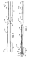
- FIGS. 4-8 another example of a rapid-exchange catheter assembly 80 is shown.
- the proximal portion of the inner member is not made from a tubular member, such as a hypertube but, rather, is replaced by a support mandrel 82 that includes a proximal end 84 connected to the control handle 28 and a distal end 86 connected to a guide wire receiving member.
- the guide wire rapid-exchange catheter assembly 80 also includes a similar outer member 88 coaxially disposed over an inner member 90.
- the arrangement of components includes a stent holder 92 and an obturator 94 which, again, is used to prevent a "snow-plowing" effect as the catheter assembly 80 is moved within the patient's vasculature.
- the guide wire receiving member 42 includes a proximal opening 96 and a distal opening 98 which creates a small conduit utilized to deliver the catheter assembly 80 over a pre-deployed guide wire (not shown).
- This inner member 90 functions in the same fashion as the previously described inner member 24 of the rapid-exchange catheter assembly 20 shown in FIGS. 1-3 .
- a support mandrel 82 rather than a hypotube, which forms the proximal portion of the inner member 90.
- the use of such a mandrel may allow for a lower delivery profile and may provide additional axial stiffness to the catheter assembly as the assembly is being pushed through the patient's anatomy.
- the outer member 88 of the rapid-exchange catheter assembly 80 is made up of several portions or sections which provide different functions. As is shown in FIGS. 4 and 5 , the outer member 88 includes a proximal portion 100 having a proximal end 102 and a distal end 104. This particular proximal portion 100 can be a tubular component which allows the proximal end 102 to be attached to the locking handle 28 which actuates the retraction of the outer member 88.
- the distal end 104 is, in turn, attached to an intermediate portion 106 which extends distally to a third section, namely, the restraining sheath portion 108 that is adapted to maintain the stent 22 in a collapsed position until it is ready to be deployed in the patient's vasculature.
- This intermediate portion 106 has a proximal end 110 attached to the distal end 104 of the proximal portion 100.
- the intermediate portion 106 also includes a distal end 112 attached to a proximal end 114 of the sheath portion 108.
- the material and shape of the component forming this section of the outer member 88 can be made from a single lumen tubing, using catheter material well known in the art.
- the intermediate portion 108 is made from a tubular member having a pair of lumens extending therethrough.
- the intermediate portion 106 has double D lumen which creates a first channel or lumen 116 through which the support mandrel 82 is designed to extend therethrough and a second channel or lumen 118 used to create a guide wire exit notch 120 that allows for positioning the movement of the guide wire receiving member 42 during deployment.
- FIG. 8 shows a cross sectional view at the bonding region of the proximal portion 100 and intermediate portion 106 and shows the two separate channels 116 and 118 which are formed in the intermediate portion 106..
- the guide wire notch 120 creates an opening to allow a guide wire to extend therethrough in the guide wire receiving member 42 formed on the inner member 90.
- the proximal end of the guide wire receiving member 42 is allowed to extend through and move axially through this second channel 118 which remains distal of the guide wire notch 120 formed in the second channel 118.
- FIG. 6 shows the cross-sectional arrangement of the guide wire receiving member 42 as it extends within the second channel 118 formed on the intermediary portion 106.
- FIGS. 9 and 10 an alternative embodiment of an inner member 130 which can be used in accordance with the present invention is disclosed.
- FIGS. 9 and 10 do not show an outer member which would be utilized in conjunction with this inner member 130 to form a composite rapid-exchange catheter assembly.
- the inner member 130 utilizes a proximal portion 132 which can be made from a tubular component such as a hypotube, as was previously disclosed in the embodiment of FIGS. 1-3 .
- the proximal portion 132 includes a proximal end 134 attached to the control handle (not shown) and a distal end 136 attached to a distal portion 138 of the inner member 130.
- the distal portion 138 is different from the previously disclosed embodiments in that the guide wire receiving member 140 is formed from a tubular material which includes a wire coil 142 encapsulated by a polymeric material, such as Pebax.
- the proximal portion 132 includes a notched region 144 which creates an opening through which a guide wire (not shown) can extend through.
- a second layer 146 which encapsulates at least a portion of the guide wire receiving member 140, could be made from a tubular material. In one aspect, the second layer 146 can be made from Nylon or similar material.
- a stent holder 148 is created between a marker band 150 which can be made from a highly radiopaque material, such as tantalum, and provides an abutting shoulder that helps to prevent the stent (not shown) from retracting proximally as the outer restraining sheath is retracted to expose the stent for deployment.
- An obturator 152 can be attached to an inner member 130.
- the guide wire receiving member helps to prevent compressibility of the inner member without decreasing the flexibility of the catheter assembly.
- the guide wire receiving member will support the direct amount of compression force that is placed on the inner member during deployment, preventing the inner member from compressing and providing accurate stent placement.
- Such a guide wire receiving member is valuable in situations in which high deployment forces can be developed during deployment. In other words, the higher the deployment force, the more the inner member will compress during deployment.
- a guide wire receiving member which utilizes a coil tubing should help to provide accurate stent placement and absorb the compression exerted on the assembly.
- Such a guide wire receiving member would still provide increased flexibility and trackability at the distal portion of the catheter assembly as it is delivered through tortuous anatomy.
- the guide wire receiving member is made from a coil which is coated with a polymeric material, such as Pebax.
- a polymeric material such as Pebax
- the intent of the use of a Pebax coating is to allow the wire coil to be easily heat bonded to other components of the inner member.
- the coil is shown coated with a polymeric material, such as Pebax, it should be noted that other similar materials could be utilized as well.
- a wire coil tubing, without a coating could possibly be utilized in creating the guide wire receiving member as well.
- the inner member 160 is shown including a proximal portion 162 made from a wire coil tubing, such as a tubing described above, and utilized to form the guide wire receiving member in the embodiment of FIGS. 9 and 10 .
- the proximal portion 162 has a proximal end 164 attached to the control handle 28 and a distal end 166 which extends into the stent holder 168 formed at the distal end of the inner member.
- a guide wire receiving member 170 also is attached to the proximal portion 162.
- a portion of the proximal portion and the guide wire receiving member 170 can be bonded together by an encapsulating layer 172 formed in the region of the stent holder 168.
- Flush holes 174 which extend into the surface of the stent holder 168 and encapsulating layer 172 allow for ease of flushing a fluid through the coil tubing to purge the catheter of air bubbles.
- the layer 172 can be made from a material such as Nylon or a similar polymeric material.
- the coil tubing which can be utilized to create the proximal portion 162 is similar to the coil tubing 142 utilized to form the guide wire receiving member 140 of the inner member 130 of FIGS. 9 and 10 .
- the coil tubing can be coated with a polymeric material, such as Pebex or similar polymeric material, to create an encapsulated tubing with a lumen extending there through to allow fluid to be introduced into the inner member to purge the composite assembly of any air bubbles.
- a polymeric material such as Pebex or similar polymeric material
- FIGS. 13A-15B an alternative design for an outer member 180 and inner member 182 made in accordance with the present invention is shown. These figures are intended to show a representative distal end portion of a composite catheter assembly which provides a guide wire exit opening 184 which is utilized to create the rapid exchange portion of the catheter assembly.
- the guide wire (not shown in FIG. 13A ) is designed to extend into an internal lumen formed in the distal portion 183 which is attached to a restraining sheath portion 185.
- the outer member 180 is shown including a anti-rotation member 186 formed adjacent to the guide wire exit opening 184.
- This anti-rotation member is designed to assume a shape which is similar to a lumen shape formed on the inner member 182. It should be remembered that for rapid-exchange catheter assemblies the inner member 182 and outer member 180 should move independent of each other, otherwise the outer member will be unable to retract proximally to deploy the self-expanding stent. While axial motion between the inner and outer members 180 and 182 is desirable, rotational motion between these components can result in undesirable misalignment of the guide wire exit notch formed within the inner and outer member. As a result, it is important to maintain the guide wire exit alignment between the inner and outer members for most rapid-exchange self-expanding stent systems. However, any design which prevents rotational motion between the inner and outer member should not affect the axial motion between members.
- the inner member 182 is shown with a proximal portion 188, made from a tubing such as hypotubing, with a taper at the distal end 190.
- the inner member includes a notched portion 192 formed on the proximal portion 188 and has a general U-shape lumen 194 for the guide wire to sit inside the lumen.
- the proximal portion 188 is attached to a guide wire receiving member 196 which extends through a stent holder 198 and obturator 200.
- the inner member has a generally U-shaped configuration for the guide wire to sit in, it is to be understood that other suitable shapes which allow the guide wire to sit within the lumen could also be utilized in conjunction with the present invention.
- the inner member 182 is shown placed within the outer member 180 in a coaxial arrangement.
- the anti-rotation member 186 of the outer member is formed in a U-shape and sits within the U-shaped lumen 190 of the inner member to keep the members aligned.
- the U-shaped anti-rotation member 186 slides within the U-shaped lumen 190 in order to affect axial movement between the inner and outer members, however, the anti-rotation member 186 prevents any rotational motion between these two members, since the similar U-shape of the anti-rotation member 186 basically encapsulates the U-shaped lumen 190 of the inner member 182 preventing any rotational movement, at least within the guide wire exit opening 184.
- the guide wire 202 normally will not move as the outer member 180 is retracted relative to the inner member 182.
- the guide wire exit opening 184 is formed on the outer member by piercing the tubular material forming the outer member with a mandrel for initially forming the guide wire exit opening.
- a guide wire which is larger than the diameter of the guide wire utilized with the rapid-exchange catheter assembly is used to create a notch within the outer member.
- the mandrel can be heated and pressed down onto the outer member to form the U-shaped anti-rotation member 186 adapted to the guide wire exit opening.
- this U-shaped member should match the same shape as the U-shaped lumen 190 formed on the inner member. With both the inner and outer member retaining the same U-shaped configuration, the two members will align together and slide axial to each other without independent rotation.
- the axial movement between the inner and outer members at the guide wire junction should not affect the positioning of the guide wire 202 within the guide wire exit notch since the inner and outer member will not rotate to misalign the respective notches formed therein. It should be appreciated to those skilled in the art that other methods for forming the U-shape on the anti-rotation member can be implemented without departing from the scope of the present invention. Also, as mentioned above, the anti-rotation member and the lumen of the inner member can be formed in shapes other than a U-shape.
- FIGS. 16-17B an alternative catheter assembly 204 is disclosed.
- This particular assembly is similar to the one shown in FIGS. 13A-15B except the means for preventing rotation which is formed on the outer member 206 differs somewhat from the previously disclosed embodiment.
- An inner member such as the one shown in FIGS. 14A and 14B , can be utilized in conjunction with this particular embodiment as well.
- the outer member 206 includes a tab-like projection or member 208 which extends into the inner lumen formed in the outer member 194.
- This tab-like member 208 has a generally U-shape and is designed to sit within the U-shaped lumen 210 which is formed in the inner member.
- This U-shaped, tab-like member 208 functions similarly as to the U-shaped anti rotation member 186 used in the previously described embodiment in that axial movement between the inner member and outer member can be achieved while preventing rotational motion between these two members.
- FIGS. 17A and 17B show the arrangement of the outer member 206 and the inner member utilizing this tab-like member 208. This shows just one particular shape which can be utilized in order to prevent rotational motion between the inner and outer members at the guide wire exit opening 212. It is to be understood that variations as to the size, location and shape of this tab-like member 208 could be implemented without departing from the scope of the present invention.
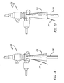
- FIGS. 18 and 19 a schematic representation of a hemostasis valve 214 is shown with a funnel introducer 216 utilized to relieve pressure which may be exerted on a catheter assembly 218 that may be placed within the hemostasis valve 214.
- a funnel introducer 216 utilized to relieve pressure which may be exerted on a catheter assembly 218 that may be placed within the hemostasis valve 214.
- One such technique utilizes the surgical insertion of a needle into a vein or artery utilizing a sheath which usually includes a hemostasis valve that inhibits blood loss as the guide wires, catheters and the like are introduced, passed through and manipulated in the introducer sheath.
- a hemostasis valve provides a fluid-tight seal at all times to prevent back-bleeding and usually offers relatively low friction when the intravascular devices are inserted therein.
- an outer member moves proximal when deployed, which motion can be hindered when clamped within the opening of the hemostasis valve.
- the outer member along with the guide wire are usually pinched between the hemostasis valve.
- the guide wire can be dragged proximal as well due to the tight fit at the hemostasis valve.
- there is a possible effect of deployment accuracy due to the friction developed between the outer member and the hemostasis valve during deployment, along with possible movement of the guide wire during stent deployment.
- any movement of the guide wire and/or catheter assembly can be critical to the accurate deployment of the stent within the patient's vasculature.
- the purpose of the funnel introducer 216 in conjunction with the hemostatic valve 214 is to relieve the pressure which may be exerted on the outer member 218 and guide wire 220.
- the introduction of the funnel introducer 216 into the hemostasis valve 214 allows the particular stent delivery system to be advanced with little force and friction caused by the hemostasis valve itself.
- the guide wire 220 can be placed within the funnel introducer 216, as is shown in FIG. 19 , or it can be placed outside the funnel introducer as is shown in FIG. 18 . When placed within the funnel introducer 216, as shown in FIG.
- the guide wire 220 is pinched between the funnel introducer 216 and the hemostasis valve 214 and does not make in contact with the catheter assembly 218 as it moves proximally during deployment. As a result, the possibility that the guide wire 220 will move in response to movement of the outer member of the catheter assembly is minimized. Additionally, when the guide wire 220 is placed within the funnel introducer 216, as is shown in FIG. 19 , movement of the guide wire is somewhat minimized while the pinching effect on the outer member should be minimized.
- the stent as described herein can be formed from any number of materials, including metals, metal alloys and polymeric materials.
- the stent may be formed from metal alloys such as stainless steel, tantalum, or the so-called heat sensitive metal alloys such as nickel titanium (NiTi).
- Stents formed from stainless steel or similar alloys typically are designed, such as in a helical coil or the like, so that they are spring biased outwardly.
- inner member and outer member can be formed from stainless steel or nickel-titanium hypotube, as noted above, or polymeric materials including polyethylenes, polyethylterpthalates, nylons, polyurethanes, elastomeric polyesters and the like.
- the more proximal portions of inner member and outer member can be formed from material that is stiffer than the distal section so that the proximal section has sufficient pushability to advance through the patient's vascular system.
- the more distal portion of inner member and outer member can be formed of a more flexible material so that the distal portion of the catheter will remain flexible and track more easily over the guide wire.
- the distal portion of the outer member which forms the restraining sheath portion of any of the embodiments of the self-expanding stent delivery system can be made with a Nylon-coated polyimide material that provides high-strength tubing, with a low-wall thickness. Such a material can resist an equal amount of hoop stress at a much lower wall thickness than with a Nylon material alone.
- a nylon material is bonded to the outside of a polyimide tubing.
- the inner surface of the polyimide tubing remains resistant to stent-strut indentation caused by the outward radial force exerted by the collapsed self-expanding stent
- the Nylon material bonded to the outside of the sheath provides the necessary tubing strength to restrain the stent in a collapsed delivery position, but with a lower wall thickness. As a result, the profile of the stent delivery system can be reduced at its distal region by utilizing such a composite material.
Landscapes
- Health & Medical Sciences (AREA)
- Engineering & Computer Science (AREA)
- Biomedical Technology (AREA)
- Cardiology (AREA)
- Oral & Maxillofacial Surgery (AREA)
- Transplantation (AREA)
- Heart & Thoracic Surgery (AREA)
- Vascular Medicine (AREA)
- Life Sciences & Earth Sciences (AREA)
- Animal Behavior & Ethology (AREA)
- General Health & Medical Sciences (AREA)
- Public Health (AREA)
- Veterinary Medicine (AREA)
- Media Introduction/Drainage Providing Device (AREA)
Claims (7)
- Kathetereinheit, die aufweist:einen Bediengriff (28),eine medizinische Vorrichtung (22),ein inneres Element (24), das einen distalen Abschnitt (36) für eine Befestigung der medizinischen Vorrichtung (22) und einen proximalen Abschnitt (52) mit einem proximalen Ende (30) aufweist, das an dem Bediengriff (28) angebracht ist, wobei das innere Element (24) außerdem ein Führungsdrahtaufnahmeelement (42) aufweist, das ein Lumen zur Aufnahme eines Führungsdrahts (50) festlegt und an dem proximalen Abschnitt (52) angebracht ist, und das Führungsdrahtaufnahmeelement (42) so ausgebildet ist, dass es sich von einem proximalen Ende (44) zu einem distalen Ende (46) erstreckt, undein äußeres Element (26), das ein proximales Ende (66) und ein distales Ende aufweist, wobei das proximale Ende (66) mit dem Bediengriff (28) verbunden ist, einen Rückhaltehülsenabschnitt (62), der einen Teil des äußeren Elements (26) bildet und so ausgebildet ist, dass er die medizinische Vorrichtung (22) zumindest teilweise bedeckt und über eine Betätigung des Bediengriffs (28) zum Freilegen der medizinischen Vorrichtung (22) zurückgezogen werden kann, wobei das äußere Element (26) ferner aufweist:einen mittleren Abschnitt (72), der sich von einem proximalen Ende (74) weg erstreckt und an dem distalen Rückhaltehülsenabschnitt (62) befestigt ist, undein proximales äußeres Element (64), das ein mit dem proximalen Ende (74) des mittleren Abschnitts (72) verbundenes distales Ende (68) aufweist, wobei sich das distale Ende (68) des proximalen äußeren Elements (64) in das proximale Ende (74) des mittleren Abschnitts (72) hinein erstreckt und der mittlere Abschnitt (72) einen größeren Durchmesser aufweist als das distale Ende (68) des proximalen äußeren Elements (64),wodurch zwischen dem proximalen äußeren Element (64) und dem mittleren Abschnitt (72) ein Raum (76) gebildet wird, der in dem äußeren Element (26) eine distale Öffnung bildet, die mit dem Führungsdrahtaufnahmeelement (42) in Verbindung steht,wobei das innere Element (24) und das äußere Element (26) für eine relative axiale Bewegung entlang einer Längsachse bemessen sind, sodass, auch wenn das äußere Element (26) über den Bediengriff (28) in proximaler Richtung zurückgezogen wird, das Führungsdrahtaufnahmeelement (42) nicht an dem sich in proximaler Richtung zurückbewegenden mittleren Abschnitt (72) fixiert wird,dadurch gekennzeichnet, dass der proximale Abschnitt (52) des inneren Elements (24) aus einem rohrförmigen Element gefertigt ist und eine Passage zum Einleiten eines Spülfluids in die Kathetereinheit ausbildet.
- Kathetereinheit nach Anspruch 1, worin der distale Rückhaltehülsenabschnitt (62) des äußeren Elements (26) aus einem mit Nylon beschichteten Polyimidwerkstoff gefertigt ist.
- Kathetereinheit nach Anspruch 2, worin der mit Nylon beschichteten Polyimidwerkstoff eine aus Polyimid gefertigte innere Lage und eine aus Nylon gefertigte äußere Lage aufweist.
- Kathetereinheit nach Anspruch 1, worin das proximale Ende (44) des Führungsdrahtaufnahmeelements (42) verschiebbar in dem Raum (76) angeordnet ist.
- Kathetereinheit nach Anspruch 1, worin das Führungsdrahtaufnahmeelement (42) innerhalb eines Lumens des mittleren Abschnitts (72) verschiebbar ist.
- Kathetereinheit nach Anspruch 1, worin das distale Ende (68) des proximalen äußeren Elements (64) sich zu einem Lumen (70) geringeren Durchmessers verjüngt.
- Kathetereinheit nach Anspruch 6, worin der am distalen Ende des proximalen äußeren Elements (64) ausgebildete, sich verjüngende Bereich und das proximale Ende (74) des mittleren Abschnitts (72) zur Ausbildung des Raums (76) zusammenwirken.
Applications Claiming Priority (2)
| Application Number | Priority Date | Filing Date | Title |
|---|---|---|---|
| US10/720,032 US7867271B2 (en) | 2003-11-20 | 2003-11-20 | Rapid-exchange delivery systems for self-expanding stents |
| PCT/US2004/034559 WO2005055881A2 (en) | 2003-11-20 | 2004-10-20 | Rapid-exchange delivery systems for self-expanding stents |
Publications (2)
| Publication Number | Publication Date |
|---|---|
| EP1689323A2 EP1689323A2 (de) | 2006-08-16 |
| EP1689323B1 true EP1689323B1 (de) | 2015-11-18 |
Family
ID=34591482
Family Applications (1)
| Application Number | Title | Priority Date | Filing Date |
|---|---|---|---|
| EP04795690.9A Expired - Lifetime EP1689323B1 (de) | 2003-11-20 | 2004-10-20 | Schnell austauschbare ablagesysteme für selbstexpandierende stents |
Country Status (6)
| Country | Link |
|---|---|
| US (1) | US7867271B2 (de) |
| EP (1) | EP1689323B1 (de) |
| CN (1) | CN1897892A (de) |
| AU (1) | AU2004296734B2 (de) |
| CA (1) | CA2548280C (de) |
| WO (1) | WO2005055881A2 (de) |
Families Citing this family (111)
| Publication number | Priority date | Publication date | Assignee | Title |
|---|---|---|---|---|
| US7018401B1 (en) | 1999-02-01 | 2006-03-28 | Board Of Regents, The University Of Texas System | Woven intravascular devices and methods for making the same and apparatus for delivery of the same |
| US8252014B2 (en) | 2004-03-03 | 2012-08-28 | Innovational Holdings Llc. | Rapid exchange balloon catheter with braided shaft |
| DE102005003632A1 (de) | 2005-01-20 | 2006-08-17 | Fraunhofer-Gesellschaft zur Förderung der angewandten Forschung e.V. | Katheter für die transvaskuläre Implantation von Herzklappenprothesen |
| WO2006113869A2 (en) * | 2005-04-20 | 2006-10-26 | Cook Incorporated | Internal cannulated joint for medical delivery systems |
| DE602006012464D1 (de) * | 2005-04-20 | 2010-04-08 | Cook Inc | Schmelzgebundenes gelenk für medizinprodukt |
| WO2006113863A2 (en) * | 2005-04-20 | 2006-10-26 | Cook Incorporated | Medical apparatus for rapid insertion |
| JP5033118B2 (ja) * | 2005-04-20 | 2012-09-26 | クック メディカル テクノロジーズ エルエルシー | テーパ状構成部品を有する医療用送達機器 |
| WO2006113866A2 (en) * | 2005-04-20 | 2006-10-26 | Cook Incorporated | Internal joint for medical devices |
| US9084694B2 (en) * | 2005-09-09 | 2015-07-21 | Boston Scientific Scimed, Inc. | Coil shaft |
| WO2007054014A1 (fr) * | 2005-11-09 | 2007-05-18 | Ning Wen | Dispositif de pose servant a la mise en place d'une endoprothese auto-expansible |
| US8529597B2 (en) | 2006-08-09 | 2013-09-10 | Coherex Medical, Inc. | Devices for reducing the size of an internal tissue opening |
| US9220487B2 (en) * | 2006-08-09 | 2015-12-29 | Coherex Medical, Inc. | Devices for reducing the size of an internal tissue opening |
| US8840655B2 (en) * | 2006-08-09 | 2014-09-23 | Coherex Medical, Inc. | Systems and devices for reducing the size of an internal tissue opening |
| WO2008051935A1 (en) | 2006-10-22 | 2008-05-02 | Idev Technologies, Inc. | Methods for securing strand ends and the resulting devices |
| JP5455633B2 (ja) | 2006-10-22 | 2014-03-26 | アイデブ テクノロジーズ インコーポレイテッド | ステント前進のためのデバイスおよび方法 |
| US9107736B2 (en) * | 2006-12-06 | 2015-08-18 | Abbott Cardiovascular Systems Inc. | Highly trackable balloon catheter system and method for collapsing an expanded medical device |
| US7815601B2 (en) * | 2007-02-05 | 2010-10-19 | Boston Scientific Scimed, Inc. | Rapid exchange enteral stent delivery system |
| EP2121100A2 (de) * | 2007-02-08 | 2009-11-25 | C.R.Bard, Inc. | Medizinische vorrichtung mit formspeicher und verfahren zu ihrer herstellung |
| US7896915B2 (en) | 2007-04-13 | 2011-03-01 | Jenavalve Technology, Inc. | Medical device for treating a heart valve insufficiency |
| US9149379B2 (en) * | 2007-07-16 | 2015-10-06 | Cook Medical Technologies Llc | Delivery device |
| US9044266B2 (en) * | 2007-09-19 | 2015-06-02 | Cook Medical Technologies Llc | Implant deployment device |
| CA2701576C (en) * | 2007-10-17 | 2016-06-21 | Angiomed Gmbh & Co. Medizintechnik Kg | Delivery system for a self-expanding device for placement in a bodily lumen |
| EP2224991B1 (de) * | 2007-11-30 | 2018-02-21 | Cook Medical Technologies LLC | Verfahren und vorrichtung für die gefässtherapie |
| US7566342B2 (en) * | 2007-12-27 | 2009-07-28 | Cook Incorporated | Delivery system for medical device |
| US8758421B2 (en) | 2008-01-30 | 2014-06-24 | Boston Scientific Scimed, Inc. | Medical systems and related methods |
| US9044318B2 (en) | 2008-02-26 | 2015-06-02 | Jenavalve Technology Gmbh | Stent for the positioning and anchoring of a valvular prosthesis |
| WO2011104269A1 (en) | 2008-02-26 | 2011-09-01 | Jenavalve Technology Inc. | Stent for the positioning and anchoring of a valvular prosthesis in an implantation site in the heart of a patient |
| GB0815339D0 (en) * | 2008-08-21 | 2008-10-01 | Angiomed Ag | Method of loading a stent into a sheath |
| WO2009135934A1 (en) * | 2008-05-09 | 2009-11-12 | Angiomed Gmbh & Co. Medizintechnik Kg | Method of loading a stent into a sheath |
| DE102008002472A1 (de) * | 2008-06-17 | 2009-12-24 | Biotronik Vi Patent Ag | Einführsystem für eine medizinische Einrichtung und Verfahren zum Betreiben eines Einführsystems für eine medizinische Einrichtung |
| US8888833B2 (en) * | 2008-11-14 | 2014-11-18 | Abbott Cardiovascular Systems Inc. | Delivery system having one piece inner member with flat distal end portion |
| US20100125324A1 (en) * | 2008-11-14 | 2010-05-20 | Medtronic Vascular, Inc. | Catheter Inner Member |
| US11406791B2 (en) | 2009-04-03 | 2022-08-09 | Scientia Vascular, Inc. | Micro-fabricated guidewire devices having varying diameters |
| US12220538B2 (en) | 2008-12-08 | 2025-02-11 | Scientia Vascular, Inc. | Micro-fabricated intravascular devices having varying diameters |
| CA2747748C (en) * | 2008-12-30 | 2014-05-20 | Wilson-Cook Medical Inc. | Delivery device |
| GB0823716D0 (en) * | 2008-12-31 | 2009-02-04 | Angiomed Ag | Stent delivery device with rolling stent retaining sheath |
| CH700478A1 (de) * | 2009-02-27 | 2010-08-31 | Schwager Medica | Katheter. |
| AU2010232448B2 (en) * | 2009-04-03 | 2013-11-14 | Scientia Vascular, Inc. | Micro-fabricated catheter and guidewire devices |
| GB0921238D0 (en) | 2009-12-03 | 2010-01-20 | Angiomed Ag | Stent device delivery system and method of making such |
| GB0921237D0 (en) | 2009-12-03 | 2010-01-20 | Angiomed Ag | Stent device delivery system and method of making such |
| GB0921236D0 (en) * | 2009-12-03 | 2010-01-20 | Angiomed Ag | Stent device delivery system and method of making such |
| GB0921240D0 (en) | 2009-12-03 | 2010-01-20 | Angiomed Ag | Stent device delivery system and method of making such |
| JP5671228B2 (ja) * | 2009-12-14 | 2015-02-18 | テルモ株式会社 | バルーンカテーテル |
| CN102113926B (zh) * | 2009-12-30 | 2013-01-23 | 微创医疗器械(上海)有限公司 | 一种医用导丝 |
| WO2011094527A1 (en) * | 2010-01-29 | 2011-08-04 | Cook Medical Technologies Llc | Mechanically expandable delivery and dilation systems |
| CN102145202B (zh) * | 2010-02-05 | 2012-12-26 | 微创医疗器械(上海)有限公司 | 一种医用导丝 |
| JPWO2011122444A1 (ja) * | 2010-03-30 | 2013-07-08 | テルモ株式会社 | ステントデリバリーシステム |
| US20120046729A1 (en) * | 2010-04-14 | 2012-02-23 | Abbott Vascular | Intraluminal scaffold having an enlarged portion |
| US8740976B2 (en) * | 2010-04-21 | 2014-06-03 | Medtronic, Inc. | Transcatheter prosthetic heart valve delivery system with flush report |
| US10856978B2 (en) | 2010-05-20 | 2020-12-08 | Jenavalve Technology, Inc. | Catheter system |
| CA2799459A1 (en) | 2010-05-25 | 2011-12-01 | Jenavalve Technology Inc. | Prosthetic heart valve and transcatheter delivered endoprosthesis comprising a prosthetic heart valve and a stent |
| US9023095B2 (en) | 2010-05-27 | 2015-05-05 | Idev Technologies, Inc. | Stent delivery system with pusher assembly |
| CA2801937C (en) | 2010-06-24 | 2021-10-19 | Cordis Corporation | Apparatus for and method of pulling a tensile member from a medical device |
| WO2012002944A1 (en) | 2010-06-29 | 2012-01-05 | Artventive Medical Group, Inc. | Reducing flow through a tubular structure |
| US9247942B2 (en) | 2010-06-29 | 2016-02-02 | Artventive Medical Group, Inc. | Reversible tubal contraceptive device |
| AU2011282909B2 (en) | 2010-07-30 | 2013-09-12 | Cook Medical Technologies Llc | Controlled release and recapture prosthetic deployment device |
| US10238833B2 (en) | 2010-08-12 | 2019-03-26 | C. R. Bard, Inc. | Access port and catheter assembly including catheter distal portion stability features |
| EP4122523A1 (de) | 2010-08-12 | 2023-01-25 | C. R. Bard, Inc. | Einstellbarer katheter mit stabilitätsfunktionen des distalen teils |
| US9149277B2 (en) * | 2010-10-18 | 2015-10-06 | Artventive Medical Group, Inc. | Expandable device delivery |
| US8540759B2 (en) | 2010-10-20 | 2013-09-24 | Stryker Corporation | Stent delivery catheter with rapid exchange capabilities |
| AU2011329446B2 (en) * | 2010-11-17 | 2015-12-24 | Boston Scientific Scimed, Inc. | Stent delivery systems and locking members for use with stent delivery systems |
| GB201020373D0 (en) | 2010-12-01 | 2011-01-12 | Angiomed Ag | Device to release a self-expanding implant |
| WO2012114780A1 (ja) * | 2011-02-24 | 2012-08-30 | テルモ株式会社 | ステントデリバリーシステム |
| CN102764168A (zh) * | 2011-05-03 | 2012-11-07 | 上海理工大学 | 弹性形状记忆可回收支架及其制作方法和使用方法 |
| US9339384B2 (en) * | 2011-07-27 | 2016-05-17 | Edwards Lifesciences Corporation | Delivery systems for prosthetic heart valve |
| WO2013056898A1 (en) | 2011-10-21 | 2013-04-25 | Jenavalve Technology Inc. | Catheter system for introducing an expandable heart valve stent into the body of a patient, insertion system with a catheter system and medical device for treatment of a heart valve defect |
| EP2849678B1 (de) | 2012-05-16 | 2022-08-10 | JenaValve Technology, Inc. | Katheterverabreichungssystem zur einführung einer dehnbaren herzklappenprothese sowie medizinische vorrichtung zur behandlung eines herzklappendefekts |
| KR101415902B1 (ko) * | 2012-05-18 | 2014-07-08 | 신경민 | 소작 겸용 스텐트 시술장치 |
| US9066828B2 (en) | 2012-06-15 | 2015-06-30 | Trivascular, Inc. | Endovascular delivery system with flexible and torqueable hypotube |
| US20140172068A1 (en) * | 2012-12-17 | 2014-06-19 | Cook Medical Technologies Llc | Restraining sheath with variable diameter medical device nesting region |
| US10413703B2 (en) * | 2012-12-31 | 2019-09-17 | Clearstream Technologies Limited | Catheter with markings to facilitate alignment |
| US8984733B2 (en) | 2013-02-05 | 2015-03-24 | Artventive Medical Group, Inc. | Bodily lumen occlusion |
| US9095344B2 (en) | 2013-02-05 | 2015-08-04 | Artventive Medical Group, Inc. | Methods and apparatuses for blood vessel occlusion |
| US9308108B2 (en) | 2013-03-13 | 2016-04-12 | Cook Medical Technologies Llc | Controlled release and recapture stent-deployment device |
| US9522057B2 (en) | 2013-03-14 | 2016-12-20 | Ethicon, Inc. | Delivery systems for the placement of surgical implants and methods of use |
| US9737308B2 (en) | 2013-06-14 | 2017-08-22 | Artventive Medical Group, Inc. | Catheter-assisted tumor treatment |
| US9737306B2 (en) | 2013-06-14 | 2017-08-22 | Artventive Medical Group, Inc. | Implantable luminal devices |
| US10149968B2 (en) | 2013-06-14 | 2018-12-11 | Artventive Medical Group, Inc. | Catheter-assisted tumor treatment |
| US9636116B2 (en) | 2013-06-14 | 2017-05-02 | Artventive Medical Group, Inc. | Implantable luminal devices |
| CN105491978A (zh) | 2013-08-30 | 2016-04-13 | 耶拿阀门科技股份有限公司 | 用于假体瓣膜的径向可折叠框架及其制造方法 |
| DE102013014523A1 (de) | 2013-09-03 | 2015-03-05 | Phenox Gmbh | Einführ- und Ablösesystem für Implantate |
| CA2944354C (en) | 2014-03-31 | 2021-08-03 | Clearstream Technologies Limited | Catheter structures for reducing fluoroscopy usage during endovascular procedures |
| US10363043B2 (en) | 2014-05-01 | 2019-07-30 | Artventive Medical Group, Inc. | Treatment of incompetent vessels |
| JP2016030033A (ja) * | 2014-07-28 | 2016-03-07 | ニプロ株式会社 | ステントデリバリーカテーテル |
| EP4088691B1 (de) * | 2014-10-13 | 2025-08-06 | Boston Scientific Medical Device Limited | Kathetereinführungssystem für eine stentklappe |
| EP3270825B1 (de) | 2015-03-20 | 2020-04-22 | JenaValve Technology, Inc. | Herzklappenprothesenzuführsystem |
| EP3632378B1 (de) | 2015-05-01 | 2024-05-29 | JenaValve Technology, Inc. | Vorrichtung mit reduzierter herzschrittmacherrate bei herzklappenersatz |
| AU2016305298B2 (en) * | 2015-08-11 | 2020-11-12 | Mokita Medical Gmbh I.Gr. | Systems and methods for removing air from medical devices |
| US10813644B2 (en) | 2016-04-01 | 2020-10-27 | Artventive Medical Group, Inc. | Occlusive implant and delivery system |
| US11065138B2 (en) | 2016-05-13 | 2021-07-20 | Jenavalve Technology, Inc. | Heart valve prosthesis delivery system and method for delivery of heart valve prosthesis with introducer sheath and loading system |
| US11052228B2 (en) | 2016-07-18 | 2021-07-06 | Scientia Vascular, Llc | Guidewire devices having shapeable tips and bypass cuts |
| US11207502B2 (en) | 2016-07-18 | 2021-12-28 | Scientia Vascular, Llc | Guidewire devices having shapeable tips and bypass cuts |
| US10646689B2 (en) | 2016-07-29 | 2020-05-12 | Cephea Valve Technologies, Inc. | Mechanical interlock for catheters |
| US11109967B2 (en) | 2016-08-29 | 2021-09-07 | Cephea Valve Technologies, Inc. | Systems and methods for loading and deploying an intravascular device |
| JP7131742B2 (ja) * | 2016-09-29 | 2022-09-06 | メリット・メディカル・システムズ・インコーポレイテッド | 血管プロテーゼを受容し、その展開を補助するための柔軟部材 |
| US11452541B2 (en) | 2016-12-22 | 2022-09-27 | Scientia Vascular, Inc. | Intravascular device having a selectively deflectable tip |
| CN110392557A (zh) | 2017-01-27 | 2019-10-29 | 耶拿阀门科技股份有限公司 | 心脏瓣膜模拟 |
| US10940030B2 (en) | 2017-03-10 | 2021-03-09 | Serenity Medical, Inc. | Method and system for delivering a self-expanding stent to the venous sinuses |
| CN106963529B (zh) * | 2017-03-27 | 2019-07-19 | 南京微创医学科技股份有限公司 | 一种快速交换支架置入系统 |
| EP4257173A3 (de) | 2017-05-26 | 2023-11-29 | Scientia Vascular, Inc. | Mikrofabrizierte medizinische vorrichtung mit nicht-helixförmiger schnittanordnung |
| US11305095B2 (en) | 2018-02-22 | 2022-04-19 | Scientia Vascular, Llc | Microfabricated catheter having an intermediate preferred bending section |
| CN111712291B (zh) | 2018-02-26 | 2022-08-16 | Cti血管公司 | 治疗血管病变的可用长度可选的导管 |
| CN110664523B (zh) * | 2018-07-03 | 2022-06-21 | 先健科技(深圳)有限公司 | 用于输送介入医疗器械的输送器 |
| US12011555B2 (en) | 2019-01-15 | 2024-06-18 | Scientia Vascular, Inc. | Guidewire with core centering mechanism |
| US12623049B2 (en) | 2019-05-02 | 2026-05-12 | Scientia Vascular, Inc. | Intravascular device with enhanced one-beam cut pattern |
| US12343485B2 (en) | 2020-01-23 | 2025-07-01 | Scientia Vascular, Inc. | High torque guidewire device |
| US12178975B2 (en) | 2020-01-23 | 2024-12-31 | Scientia Vascular, Inc. | Guidewire having enlarged, micro-fabricated distal section |
| US12296112B2 (en) | 2020-10-05 | 2025-05-13 | Scientia Vascular, Inc. | Microfabricated catheter devices with high axial strength |
| CN112263363A (zh) * | 2020-12-03 | 2021-01-26 | 李立 | 一种支架贴壁器 |
| US12171658B2 (en) | 2022-11-09 | 2024-12-24 | Jenavalve Technology, Inc. | Catheter system for sequential deployment of an expandable implant |
| TW202434330A (zh) * | 2023-01-13 | 2024-09-01 | 美商阿比奥梅德公司 | 流出管與流出管組件 |
Family Cites Families (64)
| Publication number | Priority date | Publication date | Assignee | Title |
|---|---|---|---|---|
| US3880483A (en) | 1972-04-28 | 1975-04-29 | Roberts Ind Inc | Locking device |
| US3856190A (en) | 1973-12-26 | 1974-12-24 | C Mole | Telescoping coat hanger |
| US5350395A (en) | 1986-04-15 | 1994-09-27 | Yock Paul G | Angioplasty apparatus facilitating rapid exchanges |
| US5061273A (en) | 1989-06-01 | 1991-10-29 | Yock Paul G | Angioplasty apparatus facilitating rapid exchanges |
| US4748982A (en) | 1987-01-06 | 1988-06-07 | Advanced Cardiovascular Systems, Inc. | Reinforced balloon dilatation catheter with slitted exchange sleeve and method |
| US5156594A (en) | 1990-08-28 | 1992-10-20 | Scimed Life Systems, Inc. | Balloon catheter with distal guide wire lumen |
| US6071273A (en) | 1988-02-29 | 2000-06-06 | Scimed Life Systems, Inc. | Fixed wire dilatation balloon catheter |
| US5514091A (en) | 1988-07-22 | 1996-05-07 | Yoon; Inbae | Expandable multifunctional manipulating instruments for various medical procedures |
| US5176661A (en) * | 1988-09-06 | 1993-01-05 | Advanced Cardiovascular Systems, Inc. | Composite vascular catheter |
| US5180368A (en) | 1989-09-08 | 1993-01-19 | Advanced Cardiovascular Systems, Inc. | Rapidly exchangeable and expandable cage catheter for repairing damaged blood vessels |
| US5516336A (en) | 1990-02-07 | 1996-05-14 | Advanced Cardiovascular Systems, Inc. | Readily exchangeable perfusion dilatation catheter |
| US5147379A (en) | 1990-11-26 | 1992-09-15 | Louisiana State University And Agricultural And Mechanical College | Insertion instrument for vena cava filter |
| US5743875A (en) | 1991-05-15 | 1998-04-28 | Advanced Cardiovascular Systems, Inc. | Catheter shaft with an oblong transverse cross-section |
| US5533968A (en) | 1991-05-15 | 1996-07-09 | Advanced Cardiovascular Systems, Inc. | Low profile catheter with expandable outer tubular member |
| US5154725A (en) | 1991-06-07 | 1992-10-13 | Advanced Cardiovascular Systems, Inc. | Easily exchangeable catheter system |
| US5135535A (en) | 1991-06-11 | 1992-08-04 | Advanced Cardiovascular Systems, Inc. | Catheter system with catheter and guidewire exchange |
| EP0600940B1 (de) | 1991-07-24 | 1999-02-24 | Advanced Cardiovascular Systems, Inc. | Dilatationskatheter mit niedrigem profil zur durchführung von perfusionen |
| US5389087A (en) | 1991-09-19 | 1995-02-14 | Baxter International Inc. | Fully exchangeable over-the-wire catheter with rip seam and gated side port |
| US5195978A (en) | 1991-12-11 | 1993-03-23 | Baxter International Inc. | Rapid exchange over-the-wire catheter with breakaway feature |
| CA2117386A1 (en) | 1992-01-09 | 1993-07-22 | Motasim M. Sirhan | Guidewire replacement device |
| CA2142992A1 (en) | 1992-08-25 | 1994-03-03 | Thomas Fitzmaurice | Dilatation catheter with stiffening wire |
| DE9321003U1 (de) * | 1992-12-30 | 1995-08-10 | Schneider (Usa) Inc., Plymouth, Minn. | Vorrichtung zum Ausbringen von körperimplantierbaren Stents |
| US5360401A (en) | 1993-02-18 | 1994-11-01 | Advanced Cardiovascular Systems, Inc. | Catheter for stent delivery |
| WO1995002430A1 (en) | 1993-07-15 | 1995-01-26 | Advanced Cardiovascular Systems, Inc. | Rapid exchange type intraluminal catheter with guiding element |
| US5443457A (en) | 1994-02-24 | 1995-08-22 | Cardiovascular Imaging Systems, Incorporated | Tracking tip for a short lumen rapid exchange catheter |
| US5545138A (en) * | 1994-02-28 | 1996-08-13 | Medtronic, Inc. | Adjustable stiffness dilatation catheter |
| FR2718645B1 (fr) | 1994-04-15 | 1996-07-12 | Nycomed Lab Sa | Cathéter de dilatation à échange rapide. |
| US5620417A (en) | 1994-07-07 | 1997-04-15 | Cardiovascular Imaging Systems Incorporated | Rapid exchange delivery catheter |
| US5743874A (en) * | 1994-08-29 | 1998-04-28 | Fischell; Robert E. | Integrated catheter for balloon angioplasty and stent delivery |
| EP0757570B1 (de) | 1995-02-24 | 2003-06-18 | Ave Connaught | Verstärkter schnell austauschbarer ballonkatheter |
| US5776141A (en) * | 1995-08-28 | 1998-07-07 | Localmed, Inc. | Method and apparatus for intraluminal prosthesis delivery |
| US6077295A (en) | 1996-07-15 | 2000-06-20 | Advanced Cardiovascular Systems, Inc. | Self-expanding stent delivery system |
| US6007522A (en) * | 1996-09-13 | 1999-12-28 | Boston Scientific Corporation | Single operator exchange biliary catheter |
| US5807355A (en) | 1996-12-09 | 1998-09-15 | Advanced Cardiovascular Systems, Inc. | Catheter with rapid exchange and OTW operative modes |
| US6045570A (en) * | 1997-02-11 | 2000-04-04 | Biointerventional Corporation | Biological sealant mixture and system for use in percutaneous occlusion of puncture sites and tracts in the human body and method |
| US5792144A (en) | 1997-03-31 | 1998-08-11 | Cathco, Inc. | Stent delivery catheter system |
| US5810871A (en) | 1997-04-29 | 1998-09-22 | Medtronic, Inc. | Stent delivery system |
| ATE265247T1 (de) | 1997-06-10 | 2004-05-15 | Schneider Europ Gmbh | Kathetersystem |
| US6475187B1 (en) | 1998-03-04 | 2002-11-05 | Scimed Life Systems, Inc. | Convertible catheter incorporating distal force transfer mechanism |
| US6019778A (en) * | 1998-03-13 | 2000-02-01 | Cordis Corporation | Delivery apparatus for a self-expanding stent |
| US5993460A (en) | 1998-03-27 | 1999-11-30 | Advanced Cardiovascular Systems, Inc. | Rapid exchange delivery system for stenting a body lumen |
| US6520983B1 (en) * | 1998-03-31 | 2003-02-18 | Scimed Life Systems, Inc. | Stent delivery system |
| US6132389A (en) | 1998-04-23 | 2000-10-17 | Advanced Cardiovascular Systems, Inc. | Proximally tapered guidewire tip coil |
| US6174316B1 (en) | 1998-05-28 | 2001-01-16 | Medtronic, Inc. | Stent delivery system |
| US6143021A (en) | 1998-07-10 | 2000-11-07 | American Medical Systems, Inc. | Stent placement instrument and method of assembly |
| WO2000018330A1 (en) | 1998-09-30 | 2000-04-06 | Impra, Inc. | Delivery mechanism for implantable stent |
| US6254609B1 (en) * | 1999-01-11 | 2001-07-03 | Scimed Life Systems, Inc. | Self-expanding stent delivery system with two sheaths |
| US6248122B1 (en) | 1999-02-26 | 2001-06-19 | Vascular Architects, Inc. | Catheter with controlled release endoluminal prosthesis |
| US6375676B1 (en) | 1999-05-17 | 2002-04-23 | Advanced Cardiovascular Systems, Inc. | Self-expanding stent with enhanced delivery precision and stent delivery system |
| US6290673B1 (en) | 1999-05-20 | 2001-09-18 | Conor Medsystems, Inc. | Expandable medical device delivery system and method |
| US6287329B1 (en) * | 1999-06-28 | 2001-09-11 | Nitinol Development Corporation | Stent keeper for a self-expanding stent delivery system |
| US6193686B1 (en) | 1999-06-30 | 2001-02-27 | Advanced Cardiovascular Systems, Inc. | Catheter with enhanced flexibility |
| US6179810B1 (en) | 1999-08-17 | 2001-01-30 | Advanced Cardiovascular Systems, Inc. | Catheter with a flexible and pushable shaft |
| US6613075B1 (en) | 1999-10-27 | 2003-09-02 | Cordis Corporation | Rapid exchange self-expanding stent delivery catheter system |
| US6299595B1 (en) | 1999-12-17 | 2001-10-09 | Advanced Cardiovascular Systems, Inc. | Catheters having rapid-exchange and over-the-wire operating modes |
| US6685734B1 (en) | 1999-12-17 | 2004-02-03 | Linvatec Biomaterials Oy | Urethral stent delivery system |
| US6589207B1 (en) * | 1999-12-21 | 2003-07-08 | Advanced Cardiovascular Systems, Inc. | Rapid exchange catheter having a support mandrel |
| US6436090B1 (en) * | 2000-12-21 | 2002-08-20 | Advanced Cardiovascular Systems, Inc. | Multi lumen catheter shaft |
| US6736839B2 (en) * | 2001-02-01 | 2004-05-18 | Charles Cummings | Medical device delivery system |
| US6592549B2 (en) * | 2001-03-14 | 2003-07-15 | Scimed Life Systems, Inc. | Rapid exchange stent delivery system and associated components |
| US7780693B2 (en) * | 2001-06-27 | 2010-08-24 | Salviac Limited | Catheter |
| EP1399085B1 (de) | 2001-06-27 | 2016-02-17 | Salviac Limited | Katheter |
| US7967837B2 (en) * | 2001-06-27 | 2011-06-28 | Salviac Limited | Catheter |
| US6679909B2 (en) * | 2001-07-31 | 2004-01-20 | Advanced Cardiovascular Systems, Inc. | Rapid exchange delivery system for self-expanding stent |
-
2003
- 2003-11-20 US US10/720,032 patent/US7867271B2/en not_active Expired - Fee Related
-
2004
- 2004-10-20 EP EP04795690.9A patent/EP1689323B1/de not_active Expired - Lifetime
- 2004-10-20 CA CA2548280A patent/CA2548280C/en not_active Expired - Fee Related
- 2004-10-20 WO PCT/US2004/034559 patent/WO2005055881A2/en not_active Ceased
- 2004-10-20 CN CNA2004800382068A patent/CN1897892A/zh active Pending
- 2004-10-20 AU AU2004296734A patent/AU2004296734B2/en not_active Ceased
Also Published As
| Publication number | Publication date |
|---|---|
| WO2005055881A3 (en) | 2005-08-25 |
| WO2005055881A2 (en) | 2005-06-23 |
| AU2004296734A1 (en) | 2005-06-23 |
| EP1689323A2 (de) | 2006-08-16 |
| CA2548280C (en) | 2013-08-20 |
| AU2004296734B2 (en) | 2011-08-11 |
| CN1897892A (zh) | 2007-01-17 |
| HK1088526A1 (zh) | 2006-11-10 |
| US7867271B2 (en) | 2011-01-11 |
| US20050113902A1 (en) | 2005-05-26 |
| CA2548280A1 (en) | 2005-06-23 |
Similar Documents
| Publication | Publication Date | Title |
|---|---|---|
| CA2548280C (en) | Rapid-exchange delivery systems for self-expanding stents | |
| US12186509B2 (en) | Intravascular delivery system and method for percutaneous coronary intervention | |
| JP7659579B2 (ja) | 経皮的冠動脈インターベンションのための血管内送入システム及び方法 | |
| CA2324577C (en) | Rapid exchange self-expanding stent delivery catheter system | |
| US10624739B2 (en) | Heart valve delivery system with valve catheter | |
| US5456667A (en) | Temporary stenting catheter with one-piece expandable segment | |
| US6786918B1 (en) | Stent delivery system | |
| US20150238336A1 (en) | Delivery of medical devices | |
| US20240123187A1 (en) | Intravascular delivery system and method for percutaneous coronary intervention including perfusion | |
| HK1088526B (en) | Rapid-exchange delivery systems for self-expanding stents | |
| KR102965807B1 (ko) | 경피적 관상 동맥 개입술을 위한 혈관 내 전달 시스템 및 방법 | |
| AU781743B2 (en) | Rapid exchange self-expanding stent delivery catheter system | |
| CA3270283A1 (en) | Intravascular delivery system and method for percutaneous coronary intervention including perfusion |
Legal Events
| Date | Code | Title | Description |
|---|---|---|---|
| PUAI | Public reference made under article 153(3) epc to a published international application that has entered the european phase |
Free format text: ORIGINAL CODE: 0009012 |
|
| 17P | Request for examination filed |
Effective date: 20060609 |
|
| AK | Designated contracting states |
Kind code of ref document: A2 Designated state(s): AT BE BG CH CY CZ DE DK EE ES FI FR GB GR HU IE IT LI LU MC NL PL PT RO SE SI SK TR |
|
| REG | Reference to a national code |
Ref country code: HK Ref legal event code: DE Ref document number: 1088526 Country of ref document: HK |
|
| DAX | Request for extension of the european patent (deleted) | ||
| RAP1 | Party data changed (applicant data changed or rights of an application transferred) |
Owner name: ABBOTT CARDIOVASCULAR SYSTEMS INC. |
|
| 17Q | First examination report despatched |
Effective date: 20100615 |
|
| GRAP | Despatch of communication of intention to grant a patent |
Free format text: ORIGINAL CODE: EPIDOSNIGR1 |
|
| INTG | Intention to grant announced |
Effective date: 20150518 |
|
| GRAS | Grant fee paid |
Free format text: ORIGINAL CODE: EPIDOSNIGR3 |
|
| GRAA | (expected) grant |
Free format text: ORIGINAL CODE: 0009210 |
|
| AK | Designated contracting states |
Kind code of ref document: B1 Designated state(s): AT BE BG CH CY CZ DE DK EE ES FI FR GB GR HU IE IT LI LU MC NL PL PT RO SE SI SK TR |
|
| REG | Reference to a national code |
Ref country code: GB Ref legal event code: FG4D |
|
| REG | Reference to a national code |
Ref country code: CH Ref legal event code: EP |
|
| REG | Reference to a national code |
Ref country code: AT Ref legal event code: REF Ref document number: 761130 Country of ref document: AT Kind code of ref document: T Effective date: 20151215 |
|
| REG | Reference to a national code |
Ref country code: IE Ref legal event code: FG4D |
|
| REG | Reference to a national code |
Ref country code: DE Ref legal event code: R096 Ref document number: 602004048272 Country of ref document: DE |
|
| REG | Reference to a national code |
Ref country code: NL Ref legal event code: FP |
|
| REG | Reference to a national code |
Ref country code: AT Ref legal event code: MK05 Ref document number: 761130 Country of ref document: AT Kind code of ref document: T Effective date: 20151118 |
|
| PG25 | Lapsed in a contracting state [announced via postgrant information from national office to epo] |
Ref country code: ES Free format text: LAPSE BECAUSE OF FAILURE TO SUBMIT A TRANSLATION OF THE DESCRIPTION OR TO PAY THE FEE WITHIN THE PRESCRIBED TIME-LIMIT Effective date: 20151118 Ref country code: IT Free format text: LAPSE BECAUSE OF FAILURE TO SUBMIT A TRANSLATION OF THE DESCRIPTION OR TO PAY THE FEE WITHIN THE PRESCRIBED TIME-LIMIT Effective date: 20151118 |
|
| PG25 | Lapsed in a contracting state [announced via postgrant information from national office to epo] |
Ref country code: PL Free format text: LAPSE BECAUSE OF FAILURE TO SUBMIT A TRANSLATION OF THE DESCRIPTION OR TO PAY THE FEE WITHIN THE PRESCRIBED TIME-LIMIT Effective date: 20151118 Ref country code: PT Free format text: LAPSE BECAUSE OF FAILURE TO SUBMIT A TRANSLATION OF THE DESCRIPTION OR TO PAY THE FEE WITHIN THE PRESCRIBED TIME-LIMIT Effective date: 20160318 Ref country code: SE Free format text: LAPSE BECAUSE OF FAILURE TO SUBMIT A TRANSLATION OF THE DESCRIPTION OR TO PAY THE FEE WITHIN THE PRESCRIBED TIME-LIMIT Effective date: 20151118 Ref country code: FI Free format text: LAPSE BECAUSE OF FAILURE TO SUBMIT A TRANSLATION OF THE DESCRIPTION OR TO PAY THE FEE WITHIN THE PRESCRIBED TIME-LIMIT Effective date: 20151118 Ref country code: AT Free format text: LAPSE BECAUSE OF FAILURE TO SUBMIT A TRANSLATION OF THE DESCRIPTION OR TO PAY THE FEE WITHIN THE PRESCRIBED TIME-LIMIT Effective date: 20151118 Ref country code: GR Free format text: LAPSE BECAUSE OF FAILURE TO SUBMIT A TRANSLATION OF THE DESCRIPTION OR TO PAY THE FEE WITHIN THE PRESCRIBED TIME-LIMIT Effective date: 20160219 |
|
| PG25 | Lapsed in a contracting state [announced via postgrant information from national office to epo] |
Ref country code: CZ Free format text: LAPSE BECAUSE OF FAILURE TO SUBMIT A TRANSLATION OF THE DESCRIPTION OR TO PAY THE FEE WITHIN THE PRESCRIBED TIME-LIMIT Effective date: 20151118 |
|
| REG | Reference to a national code |
Ref country code: DE Ref legal event code: R097 Ref document number: 602004048272 Country of ref document: DE |
|
| REG | Reference to a national code |
Ref country code: HK Ref legal event code: GR Ref document number: 1088526 Country of ref document: HK |
|
| PG25 | Lapsed in a contracting state [announced via postgrant information from national office to epo] |
Ref country code: EE Free format text: LAPSE BECAUSE OF FAILURE TO SUBMIT A TRANSLATION OF THE DESCRIPTION OR TO PAY THE FEE WITHIN THE PRESCRIBED TIME-LIMIT Effective date: 20151118 Ref country code: RO Free format text: LAPSE BECAUSE OF FAILURE TO SUBMIT A TRANSLATION OF THE DESCRIPTION OR TO PAY THE FEE WITHIN THE PRESCRIBED TIME-LIMIT Effective date: 20151118 Ref country code: SK Free format text: LAPSE BECAUSE OF FAILURE TO SUBMIT A TRANSLATION OF THE DESCRIPTION OR TO PAY THE FEE WITHIN THE PRESCRIBED TIME-LIMIT Effective date: 20151118 Ref country code: DK Free format text: LAPSE BECAUSE OF FAILURE TO SUBMIT A TRANSLATION OF THE DESCRIPTION OR TO PAY THE FEE WITHIN THE PRESCRIBED TIME-LIMIT Effective date: 20151118 |
|
| PLBE | No opposition filed within time limit |
Free format text: ORIGINAL CODE: 0009261 |
|
| STAA | Information on the status of an ep patent application or granted ep patent |
Free format text: STATUS: NO OPPOSITION FILED WITHIN TIME LIMIT |
|
| 26N | No opposition filed |
Effective date: 20160819 |
|
| PG25 | Lapsed in a contracting state [announced via postgrant information from national office to epo] |
Ref country code: SI Free format text: LAPSE BECAUSE OF FAILURE TO SUBMIT A TRANSLATION OF THE DESCRIPTION OR TO PAY THE FEE WITHIN THE PRESCRIBED TIME-LIMIT Effective date: 20151118 |
|
| PG25 | Lapsed in a contracting state [announced via postgrant information from national office to epo] |
Ref country code: BE Free format text: LAPSE BECAUSE OF FAILURE TO SUBMIT A TRANSLATION OF THE DESCRIPTION OR TO PAY THE FEE WITHIN THE PRESCRIBED TIME-LIMIT Effective date: 20151118 |
|
| REG | Reference to a national code |
Ref country code: CH Ref legal event code: PL |
|
| PG25 | Lapsed in a contracting state [announced via postgrant information from national office to epo] |
Ref country code: MC Free format text: LAPSE BECAUSE OF FAILURE TO SUBMIT A TRANSLATION OF THE DESCRIPTION OR TO PAY THE FEE WITHIN THE PRESCRIBED TIME-LIMIT Effective date: 20151118 |
|
| REG | Reference to a national code |
Ref country code: FR Ref legal event code: ST Effective date: 20170630 |
|
| PG25 | Lapsed in a contracting state [announced via postgrant information from national office to epo] |
Ref country code: LI Free format text: LAPSE BECAUSE OF NON-PAYMENT OF DUE FEES Effective date: 20161031 Ref country code: CH Free format text: LAPSE BECAUSE OF NON-PAYMENT OF DUE FEES Effective date: 20161031 Ref country code: FR Free format text: LAPSE BECAUSE OF NON-PAYMENT OF DUE FEES Effective date: 20161102 |
|
| PG25 | Lapsed in a contracting state [announced via postgrant information from national office to epo] |
Ref country code: LU Free format text: LAPSE BECAUSE OF NON-PAYMENT OF DUE FEES Effective date: 20161020 |
|
| PG25 | Lapsed in a contracting state [announced via postgrant information from national office to epo] |
Ref country code: CY Free format text: LAPSE BECAUSE OF FAILURE TO SUBMIT A TRANSLATION OF THE DESCRIPTION OR TO PAY THE FEE WITHIN THE PRESCRIBED TIME-LIMIT Effective date: 20151118 Ref country code: HU Free format text: LAPSE BECAUSE OF FAILURE TO SUBMIT A TRANSLATION OF THE DESCRIPTION OR TO PAY THE FEE WITHIN THE PRESCRIBED TIME-LIMIT; INVALID AB INITIO Effective date: 20041020 |
|
| PG25 | Lapsed in a contracting state [announced via postgrant information from national office to epo] |
Ref country code: TR Free format text: LAPSE BECAUSE OF FAILURE TO SUBMIT A TRANSLATION OF THE DESCRIPTION OR TO PAY THE FEE WITHIN THE PRESCRIBED TIME-LIMIT Effective date: 20151118 |
|
| PG25 | Lapsed in a contracting state [announced via postgrant information from national office to epo] |
Ref country code: BG Free format text: LAPSE BECAUSE OF FAILURE TO SUBMIT A TRANSLATION OF THE DESCRIPTION OR TO PAY THE FEE WITHIN THE PRESCRIBED TIME-LIMIT Effective date: 20151118 |
|
| PGFP | Annual fee paid to national office [announced via postgrant information from national office to epo] |
Ref country code: IE Payment date: 20190925 Year of fee payment: 16 Ref country code: NL Payment date: 20190927 Year of fee payment: 16 |
|
| PGFP | Annual fee paid to national office [announced via postgrant information from national office to epo] |
Ref country code: GB Payment date: 20190925 Year of fee payment: 16 |
|
| PGFP | Annual fee paid to national office [announced via postgrant information from national office to epo] |
Ref country code: DE Payment date: 20190917 Year of fee payment: 16 |
|
| REG | Reference to a national code |
Ref country code: DE Ref legal event code: R119 Ref document number: 602004048272 Country of ref document: DE |
|
| REG | Reference to a national code |
Ref country code: NL Ref legal event code: MM Effective date: 20201101 |
|
| GBPC | Gb: european patent ceased through non-payment of renewal fee |
Effective date: 20201020 |
|
| PG25 | Lapsed in a contracting state [announced via postgrant information from national office to epo] |
Ref country code: DE Free format text: LAPSE BECAUSE OF NON-PAYMENT OF DUE FEES Effective date: 20210501 Ref country code: NL Free format text: LAPSE BECAUSE OF NON-PAYMENT OF DUE FEES Effective date: 20201101 |
|
| PG25 | Lapsed in a contracting state [announced via postgrant information from national office to epo] |
Ref country code: GB Free format text: LAPSE BECAUSE OF NON-PAYMENT OF DUE FEES Effective date: 20201020 |
|
| PG25 | Lapsed in a contracting state [announced via postgrant information from national office to epo] |
Ref country code: IE Free format text: LAPSE BECAUSE OF NON-PAYMENT OF DUE FEES Effective date: 20201020 |