EP1688761A1 - Procédé et dispositif destinés à la découverte de systèmes optiques dans une zone de terrain - Google Patents
Procédé et dispositif destinés à la découverte de systèmes optiques dans une zone de terrain Download PDFInfo
- Publication number
- EP1688761A1 EP1688761A1 EP06001918A EP06001918A EP1688761A1 EP 1688761 A1 EP1688761 A1 EP 1688761A1 EP 06001918 A EP06001918 A EP 06001918A EP 06001918 A EP06001918 A EP 06001918A EP 1688761 A1 EP1688761 A1 EP 1688761A1
- Authority
- EP
- European Patent Office
- Prior art keywords
- mirror
- telescope
- light beam
- laser
- optical
- Prior art date
- Legal status (The legal status is an assumption and is not a legal conclusion. Google has not performed a legal analysis and makes no representation as to the accuracy of the status listed.)
- Granted
Links
Images


Classifications
-
- G—PHYSICS
- G01—MEASURING; TESTING
- G01S—RADIO DIRECTION-FINDING; RADIO NAVIGATION; DETERMINING DISTANCE OR VELOCITY BY USE OF RADIO WAVES; LOCATING OR PRESENCE-DETECTING BY USE OF THE REFLECTION OR RERADIATION OF RADIO WAVES; ANALOGOUS ARRANGEMENTS USING OTHER WAVES
- G01S17/00—Systems using the reflection or reradiation of electromagnetic waves other than radio waves, e.g. lidar systems
- G01S17/02—Systems using the reflection of electromagnetic waves other than radio waves
- G01S17/04—Systems determining the presence of a target
-
- G—PHYSICS
- G02—OPTICS
- G02B—OPTICAL ELEMENTS, SYSTEMS OR APPARATUS
- G02B23/00—Telescopes, e.g. binoculars; Periscopes; Instruments for viewing the inside of hollow bodies; Viewfinders; Optical aiming or sighting devices
- G02B23/02—Telescopes, e.g. binoculars; Periscopes; Instruments for viewing the inside of hollow bodies; Viewfinders; Optical aiming or sighting devices involving prisms or mirrors
- G02B23/10—Telescopes, e.g. binoculars; Periscopes; Instruments for viewing the inside of hollow bodies; Viewfinders; Optical aiming or sighting devices involving prisms or mirrors reflecting into the field of view additional indications, e.g. from collimator
-
- F—MECHANICAL ENGINEERING; LIGHTING; HEATING; WEAPONS; BLASTING
- F41—WEAPONS
- F41G—WEAPON SIGHTS; AIMING
- F41G3/00—Aiming or laying means
- F41G3/14—Indirect aiming means
- F41G3/147—Indirect aiming means based on detection of a firing weapon
-
- G—PHYSICS
- G02—OPTICS
- G02B—OPTICAL ELEMENTS, SYSTEMS OR APPARATUS
- G02B23/00—Telescopes, e.g. binoculars; Periscopes; Instruments for viewing the inside of hollow bodies; Viewfinders; Optical aiming or sighting devices
- G02B23/14—Viewfinders
Definitions
- the invention relates to a method for detecting optical systems in a terrain area, in which the terrain area is optically scanned by means of a movable mirror and the position of the optical system is determined from a measurement carried out by means of a laser arrangement and visualized.
- the invention further relates to an apparatus for detecting optical systems in a terrain area, comprising a, comprising a movable mirror laser arrangement, with a control device for determining the position of the optical system from a measurement performed by means of the laser array and with a device for optical displays of the position.
- optical systems means optically locatable systems, for example hostile search or target systems, but above all also shooters, in particular snipers. There is a need for systems to detect such hostile optical systems or shooters to locate and possibly under fire.
- a terrain area is scanned by pivoting a mirror and the received light signals are fed to an IR-sensitive, two-dimensional array.
- the array detects the firing of a bullet fired from a shooter due to the evolution of heat of the bullet and, in such a case, initiates the second stage.
- the trajectory of the projectile is tracked by means of a laser radar by pivoting the mirror and from the trajectory of the shooting point of the projectile and thus the position of the shooter is calculated.
- the captured image of the target area is displayed on a screen of a PC.
- This known system therefore has the disadvantage that the shooter must have fired at least one shot before he locates can be. Furthermore, the device is very bulky and probably only stationary use with all its components.
- devices are commercially available in which a large-area illumination of a target area with laser light and a simultaneous observation of the illuminated target area takes place by means of a CCD camera.
- the apparatus employs a laser light source having a light output one-dimensionally expanded in the vertical direction, which is directed to a target area.
- a vertically stacked array of detectors receives the light reflected from the target area.
- a telescope-type optical observation system is provided.
- This system also has the disadvantage that it is very difficult and cumbersome to handle.
- the document US Pat. No. 6,603,134 B1 describes a device for military applications, which involves optically detecting the presence of an enemy in order to subsequently render it harmless.
- the primary aim is to destroy an opponent's infrared measuring devices by means of correspondingly strong laser beams or at least render them incapacitated for work.
- the device is intended to combat an enemy object, which may be, for example, an enemy satellite, which spies its own land from space, or even a human or animal eye.
- the object is defined as a retroreflector.
- the light beams emitted by an optical search device of the device are retroreflected by the object and are transmitted to a detector as reflected light beams.
- the device is thereby pivoted to scan a spatial area by means of a scanning device.
- the reflected signal picked up and processed by the detector is supplied to a so-called use system.
- This system controls the scanning device to follow a moving object. But it can also be used to control a high-energy laser gun, which makes harmless the targeted object by means of a high-energy laser beam. Image processing or display is not provided in this device.
- the document US 4 112 300 A describes a device for disturbing or destroying an enemy infrared device.
- an image of an enemy object is reflected in a telescope by processing the incident light.
- 2D or 3D scanners are known for measuring large rooms, tunnels and the like.
- a laser beam emitted via a periodically pivoted or a rotating mirror in a plane and the reflected light from the environment over the same Mirror is directed to a detector.
- Such a 3D scanner is described in DE 44 12 044 A1.
- the invention is the object of developing a method and an apparatus of the type mentioned in such a way that the above-mentioned disadvantages are avoided.
- a method and a device are to be provided, which make it possible with a compact and lightweight device, an optical system, in particular a shooter to locate before firing, the device preferably the position of the optical system and the shooter with a conventional telescope displays.
- this object is achieved in that the position of the optical system determined directly from the measurement carried out by means of the laser array by evaluating the intensity of a reflected light from an optical surface of the optical system of the laser array and is reflected in a telescope.
- the object is achieved in that the control unit, the position of the optical system directly from the measurement carried out by means of the laser array by evaluating the Intensity of a light beam of the laser array reflected from an optical surface of the optical system determines that the optical display device is a telescope and that means for mirroring the position of the optical system into the telescope are provided.
- the telescope is a riflescope.
- This measure has the advantage that the optical system, in particular a detected sniper, can be targeted immediately after determination of its position and possibly taken under fire.
- the mirror is pivoted or, in the case of one embodiment of the device according to the invention, the mirror is a vibrating mirror pivotable about an oscillating axis by means of a vibration drive.
- the oscillating drive is preferably designed as a torque motor.
- the mirror is pivoted at a frequency which corresponds to the resonant frequency of the system of oscillating drive and mirror.
- This measure has the advantage that the required for the present purposes, relatively small elevation range can be traversed in a simple manner. In contrast, each rotation of the mirror would take 360 °, although only an angle of eg 6 ° -10 ° is needed here.
- the use of a torque motor as a vibratory drive has the advantage that with little effort and using commercially available components a fast and precisely controlled pivotal movement of the mirror can be effected.
- the adjustment of the swing frequency to the value of the resonant frequency of the oscillating system has the advantage that the pivoting movement of the mirror can be realized with the lowest possible power consumption. This is particularly important for portable devices with a power supply from batteries.
- the mirror is pivoted by means of a vibration drive about a horizontal axis and the laser assembly together with the telescope manually in a horizontal plane.
- This measure has the advantage that the terrain area to be scanned can be quickly and easily checked by the user of the system executing a corresponding horizontal pivot.
- the oscillating axis of the mirror is a horizontal axis in a position of use of the device.
- This measure also has the advantage of being able to scan a terrain section by manual swiveling by hand.
- the laser arrangement is contained in a detection device and the detection device can be placed on the telescope in a first variant at the top and in a second variant at the front.
- This measure has the advantage that the system can be placed with a handle on the telescope, for example, can be plugged.
- the laser arrangement has a light source, whose light beam is directed by means of a first deflection mirror along an optical axis onto the mirror and from there on the terrain area is steered, and that the light beam reflected by the optical system is directed to a photoelement via the mirror along the optical axis.
- This measure has the advantage that both the emitted as well as the received light beam are passed over the same mirror and that an extremely compact design is created, which makes it particularly suitable to form the device as an attachment for a telescope.
- the light source is a laser diode.
- the laser diode a light beam of a wavelength in the near infrared range, preferably in the range of 1,450 to 1,600 nm, in particular of about 1,500 nm or a light beam of a wavelength in the transition from the visible to the invisible region, preferably in the range of 750 to 900 nm , in particular emit from about 800 nm.
- an InGaAs laser diode is preferably used, in the latter case preferably a GaAs laser diode.
- This measure has the advantage that, depending on the application, an "eye-safe" spectral range can be selected.
- a good effect is achieved when the laser diode is arranged downstream of a cylindrical lens.
- This measure has the advantage that the usually elliptical cross section of the light exit is converted in a laser diode in a circular cross section.
- the photoelement is an InGaAs PIN diode (wavelength 1,450 to 1,600 nm) or an Si diode (wavelength 750 to 900 nm).
- an optical filter tuned to the wavelength of the light emitted by the light source is arranged in front of the photoelement.
- This measure has the advantage that the signal / noise ratio is improved by reducing the influence of extraneous light.
- the mirror is arranged in a convergent section of the beam path of the light beam emitted by the light source.
- This measure has the advantage that a compact structure is created. On the other hand, an arrangement in a parallel section is also possible.
- the means comprise a further light source, wherein the further light source directs a further light beam having a wavelength in the visible range on the mirror, and the further light beam reflected by the mirror is reflected into the telescope.
- This measure has the advantage of providing a pictorial representation of the position of the optical system in the visible range which can be easily mirrored in the telescope.
- the further light beam is preferably directed to one side of the mirror, which lies opposite the side on which the reflected light beam impinges.
- This measure has the advantage that a particularly simple realization for providing the representation of the position, e.g. achieved the shooter, while an effective decoupling of the measuring circuit and the circuit is achieved.
- the mirror is pivoted about an oscillating axis.
- the further light beam is preferably reflected from the front through an objective lens of the telescope into the telescope.
- the laser arrangement and the means preferably have the same focal length.
- This measure has the advantage that the magnification is the same. If the system is correctly adjusted, this represents a one-to-one system. Targets are always displayed in the right place, regardless of the relative adjustment between the measuring system and the telescope.
- 10 denotes a handgun, in the case shown a rifle. It is understood that the invention can be used not only in this type of weapons but also in other weapons, such as mobile launchers for slow-flying projectiles, such as grenade launcher.
- the sighting device 14 On a run 12 of the handgun 10, a sighting device designated 14 is arranged.
- the sighting device 14 consists of a sighting telescope 16 with an eyecup 18.
- a detection device 20 At the top of the telescopic sight 16, a detection device 20 is placed, for example plugged.
- the detection device 20 has a reflecting device 21, with which light signals can be reflected in front of the telescopic sight 16.
- the recognizer 20 is for detecting optical systems in a terrain.
- an "optical system” is to be understood as optically locatable systems, for example hostile search or target systems, but above all also to shooters, in particular snipers.
- a user of the handgun 10 When a user of the handgun 10 nears a terrain in which enemy snipers are suspected as part of a military mission, he first places the recognizer 20 on the rifle scope 16. He then looks at the terrain in question through the riflescope 16 by slowly pivoting the handgun 10 with the riflescope 16 sideways across the terrain. The detection device 20 checks the terrain and displays the position of a sniper in the image of the scope 16, as soon as such a sniper was discovered and located.
- the detection device 20 can be used not only together with a telescopic sight 16 but also in conjunction with other optical observation devices, eg with telescopes, periscopes, cameras and the like.
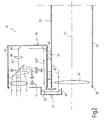
- FIGS. 2 and 3 show details of the recognition device 20.
- the difference between the two exemplary embodiments illustrated in FIGS. 2 and 3 consists only in that in the exemplary embodiment according to FIG. 2 the recognition device 20 - as shown in FIG. 1 - is placed on top of the telescopic sight 16 is set, while in the embodiment of Figure 3, the detection device 20a is placed on the front of the scope 16 a.
- the same reference numerals are used for the same elements in Figures 2 and 3, in modified elements, an "a" is added in Figure 3.
- the details are shown in more detail in FIG. 3, so that reference will be made below to both figures, unless stated otherwise.
- the telescopic sight 16 runs forward into a tube 30 and has a first optical axis 32.
- the tube 30 encloses at its front end 36 an objective lens 34 of the riflescope 16.
- connection piece 38 of the tube 40a of the recognition device 20a is placed or pushed onto the front end 36.
- the detection device 20 or 20a can therefore be placed in a simple manner on top or front of the scope 16.
- the tube 40 or 40a of the detection device 20 or 20a encloses a laser arrangement 41.
- the laser arrangement 41 has a light source 42.
- the light source 42 is preferably a laser diode.
- This can work in a first variant in the "eye-safe" spectral range, e.g. at a wavelength in the range of 1,450 to 1,600 nm, preferably of about 1,500 nm, ie in the near IR range.
- the laser diode is then preferably an InGaAs laser diode.
- a GaAs laser diode is preferably used.
- the light source 42 generates a transmitted light beam 43, preferably in a direction parallel to the first optical axis 32, ie in the normal position of use horizontal direction. Since conventional laser diodes have an oval spot, a cylindrical lens 44 is connected downstream to make the oval spot circular. This circular light beam now strikes a deflecting mirror 46, which deflects it preferably by about 90 °, in FIG. 2 and 3 thus upwards along a second optical axis 48.
- the oscillating mirror 50 is arranged in the upper region of the tube 40.
- the oscillating mirror 50 is a perpendicular to the plane of the figure 2, in the normal Use position so horizontal swing axle 52 pivotally, as indicated by a double arrow 54.
- an oscillating drive 56 which is indicated very schematically in FIG. 3, is provided which is connected to the oscillating mirror 50 via an operative connection 58.
- the oscillating mirror 50 is periodically pivoted at a frequency of eg 100 Hz at an angle of eg 5 ° -20 °.
- the oscillating drive 56 is preferably designed as a torque motor.
- the vibratory drive 56 is also preferably operated at a frequency corresponding to the resonant frequency of the oscillatory drive 56 and oscillating mirror 50 system.
- the resonance characteristic of this system can be further optimized by springs and the like.
- the transmitted light beam 43 'strikes a front side 60 of the oscillating mirror 50 from the bottom and is deflected into a third optical axis 62, which in the central position of the oscillating mirror 50 preferably extends substantially parallel to the first optical axis 32.
- the redirected transmitted light beam 43 "passes through a collimator lens 64 so that it emerges from the detection device 20 at the front as a parallel light beam.
- the reflective element may be an optical system having an (intermediate) image plane in which a plane optical surface acting as a retroreflector is disposed.
- This can be, for example, a sniper scope Be 65, in the intermediate image plane a reticle is applied to a plane-parallel glass plate.
- a reflective element but also comes an eye of the sniper 65 into consideration.
- a received light beam 66 reflected by the sniper 65 passes from the front into the recognizer 20 along the third optical axis 62.
- the received light beam 66 is incident thereon on the front side 60 of the oscillating mirror 50 and is reversed along the path of the transmitted light beam 43, i. along the second optical axis 48 deflected downward.
- the deflected received light beam 66 'passes through this way an interference filter 68, which is tuned to its wavelength. It then finally falls on a photoelement 70.
- the photoelement 70 is preferably an InGaAs PIN diode (wavelength 1,450 to 1,600 nm) or a Si diode (wavelength 750 to 900 nm).
- the photoelement 70 is connected via a line 72 to a control unit 74.
- the controller 74 includes a comparator whose threshold is set such that discrimination between "normal" reflected light and the more intense light reflected by the sniper 65 is possible.
- the controller 74 has a plurality of outputs, e.g. with the oscillating drive 56, but in particular with a further light source 80 connect.
- the further light source 80 is preferably likewise a laser diode, which, however, necessarily works in the visible spectral range, for example in the green range, ie around 530 nm wavelength.
- the further light source 80 is from the controller 74th activated when a received light beam 66 lying above the threshold value was detected by the photoelement 70. This happens so fast that the mirror 50 is at this moment practically still in the same angular position in which this threshold has been detected.
- the further light source 80 transmits its visible light beam 82 onto a reflective rear side 84 of the mirror 50.
- the light beam 82 is therefore deflected in a direction along the third optical axis 62.
- the redirected light beam 82 'then passes through a collimator lens 86.
- the light beam 82 is then four times by means of deflecting mirrors 88, 90, 92 and 94 respectively deflected by 90 °. It then runs parallel to the third optical axis 62 and thus also parallel to the first optical axis 32.
- the deflecting mirrors 92 and 94 are located in the mirror device 21 whose output (deflecting mirror 94) is directed from the front into the telescopic sight 16 and onto the objective lens 34 is.
- the light beam 82 ' is deflected by 90 ° by means of deflecting mirrors 88 and 90a only twice. It then likewise runs parallel to the third optical axis 62 and thus also parallel to the first optical axis 32.
- the light beam 82 "falls in both cases from the front into the objective lens 34 of the rifle scope 16.
- the detected position of the sniper 65 appears as a pixel in the image of the riflescope 16, so that the user of the handgun 10 Align this weapon immediately on the detected position and may take the sniper under attack if necessary.
- the focal lengths of the transmitting / receiving optics on the one hand and the collimator lens 86 on the other hand are preferably chosen to be equal. If the system is correctly adjusted, this then constitutes a so-called 1: 1 system and always sets goals, regardless of the relative adjustment between the recognition device 20 and the target and observation system, at the correct location.
Landscapes
- Physics & Mathematics (AREA)
- Engineering & Computer Science (AREA)
- General Physics & Mathematics (AREA)
- Electromagnetism (AREA)
- Astronomy & Astrophysics (AREA)
- Optics & Photonics (AREA)
- General Engineering & Computer Science (AREA)
- Computer Networks & Wireless Communication (AREA)
- Radar, Positioning & Navigation (AREA)
- Remote Sensing (AREA)
- Telescopes (AREA)
- Optical Radar Systems And Details Thereof (AREA)
Applications Claiming Priority (1)
| Application Number | Priority Date | Filing Date | Title |
|---|---|---|---|
| DE102005006726A DE102005006726A1 (de) | 2005-02-03 | 2005-02-03 | Verfahren und Vorrichtung zum Entdecken von optischen Systemen in einem Geländebereich |
Publications (2)
| Publication Number | Publication Date |
|---|---|
| EP1688761A1 true EP1688761A1 (fr) | 2006-08-09 |
| EP1688761B1 EP1688761B1 (fr) | 2011-04-06 |
Family
ID=36463343
Family Applications (1)
| Application Number | Title | Priority Date | Filing Date |
|---|---|---|---|
| EP06001918A Expired - Fee Related EP1688761B1 (fr) | 2005-02-03 | 2006-01-31 | Procédé et dispositif destinés à la découverte de systèmes optiques dans une zone de terrain |
Country Status (3)
| Country | Link |
|---|---|
| US (1) | US7443494B1 (fr) |
| EP (1) | EP1688761B1 (fr) |
| DE (2) | DE102005006726A1 (fr) |
Cited By (4)
| Publication number | Priority date | Publication date | Assignee | Title |
|---|---|---|---|---|
| FR2915000A1 (fr) * | 2007-04-11 | 2008-10-17 | Cie Ind Des Lasers Cilas Sa | Procede et dispositif a un laser pour la detection de systemes optiques grossissants |
| WO2018011218A1 (fr) * | 2016-07-15 | 2018-01-18 | Fn Herstal S.A. | Lunette de visée |
| WO2018206517A1 (fr) * | 2017-05-12 | 2018-11-15 | Robert Bosch Gmbh | Optique d'emetteur conçu pour un système lidar, système optique pour un système lidar, système lidar et dispositif de travail |
| CN111065960A (zh) * | 2017-09-11 | 2020-04-24 | 鲁普+哈伯拉克光学有限公司 | 渐进式多焦点镜片及其制造方法 |
Families Citing this family (6)
| Publication number | Priority date | Publication date | Assignee | Title |
|---|---|---|---|---|
| US8018579B1 (en) * | 2005-10-21 | 2011-09-13 | Apple Inc. | Three-dimensional imaging and display system |
| DE102006013340A1 (de) * | 2006-03-23 | 2007-09-27 | Carl Zeiss Optronics Gmbh | Vorrichtung und Verfahren zum Entdecken von optischen Systemen in einem Geländebereich |
| US7843557B2 (en) * | 2007-09-28 | 2010-11-30 | Cardinal Scientific, Inc. | Method and system for detecting retroreflectors |
| US8842015B2 (en) * | 2011-07-13 | 2014-09-23 | Safety Lab Holdings Limited | System for preventing friendly fire accidents |
| US10354448B1 (en) | 2013-03-15 | 2019-07-16 | Lockheed Martin Corporation | Detection of optical components in a scene |
| US10042154B1 (en) * | 2017-02-06 | 2018-08-07 | Bushnell Inc. | System and method for introducing display image into afocal optics device |
Citations (10)
| Publication number | Priority date | Publication date | Assignee | Title |
|---|---|---|---|---|
| US4112300A (en) | 1966-07-18 | 1978-09-05 | International Telephone And Telegraph Corporation | Infrared electronic countermeasures |
| EP0614103A1 (fr) | 1993-03-03 | 1994-09-07 | Thomson-Csf | Lunette à miroirs oscillants pour la vision infrarouge |
| DE4412044A1 (de) | 1994-04-08 | 1995-10-12 | Leuze Electronic Gmbh & Co | Optoelektronische Vorrichtung zum Erfassen von Gegenständen in einem Überwachungsbereich |
| US5528418A (en) | 1993-11-30 | 1996-06-18 | The United States Of America As Represented By The Secretary Of The Navy | Night augmented day scope |
| FR2736731A1 (fr) | 1993-04-13 | 1997-01-17 | Matra Defense | Dispositif de detection d'organes optiques pointes sur le dispositif |
| US5793034A (en) | 1995-09-18 | 1998-08-11 | Daedalus Enterprises, Inc. | Target detection system utilizing multiple optical criteria |
| US6057915A (en) | 1996-06-21 | 2000-05-02 | Thermotrex Corporation | Projectile tracking system |
| US6603134B1 (en) | 1967-03-10 | 2003-08-05 | Bae Systems Information And Electronic Systems Integration Inc. | Optical detection system |
| WO2003102626A1 (fr) | 2002-05-31 | 2003-12-11 | Federalnoe Gosudarstvennoe Unitarnoe Predpriyatie 'osoboe Konstruktorskoe Byuro Vysokoenergeticheskikh Laserov 'granat' Imeni V.K.Orlova' | Dispositif de detection d'objets optiques et optoelectroniques |
| WO2006045271A1 (fr) | 2004-10-29 | 2006-05-04 | Jenoptik Laser, Optik, Systeme Gmbh | Dispositif et procede pour identifier et localiser des systemes de contre-observation optique |
Family Cites Families (2)
| Publication number | Priority date | Publication date | Assignee | Title |
|---|---|---|---|---|
| US4926050A (en) * | 1988-03-02 | 1990-05-15 | Spectra-Physics, Inc. | Scanning laser based system and method for measurement of distance to a target |
| JP4180718B2 (ja) * | 1999-01-29 | 2008-11-12 | 株式会社トプコン | 回転レーザ装置 |
-
2005
- 2005-02-03 DE DE102005006726A patent/DE102005006726A1/de not_active Withdrawn
-
2006
- 2006-01-31 EP EP06001918A patent/EP1688761B1/fr not_active Expired - Fee Related
- 2006-01-31 DE DE502006009232T patent/DE502006009232D1/de active Active
- 2006-02-01 US US11/344,824 patent/US7443494B1/en not_active Expired - Fee Related
Patent Citations (11)
| Publication number | Priority date | Publication date | Assignee | Title |
|---|---|---|---|---|
| US4112300A (en) | 1966-07-18 | 1978-09-05 | International Telephone And Telegraph Corporation | Infrared electronic countermeasures |
| US6603134B1 (en) | 1967-03-10 | 2003-08-05 | Bae Systems Information And Electronic Systems Integration Inc. | Optical detection system |
| EP0614103A1 (fr) | 1993-03-03 | 1994-09-07 | Thomson-Csf | Lunette à miroirs oscillants pour la vision infrarouge |
| FR2736731A1 (fr) | 1993-04-13 | 1997-01-17 | Matra Defense | Dispositif de detection d'organes optiques pointes sur le dispositif |
| US5528418A (en) | 1993-11-30 | 1996-06-18 | The United States Of America As Represented By The Secretary Of The Navy | Night augmented day scope |
| DE4412044A1 (de) | 1994-04-08 | 1995-10-12 | Leuze Electronic Gmbh & Co | Optoelektronische Vorrichtung zum Erfassen von Gegenständen in einem Überwachungsbereich |
| US5793034A (en) | 1995-09-18 | 1998-08-11 | Daedalus Enterprises, Inc. | Target detection system utilizing multiple optical criteria |
| US6057915A (en) | 1996-06-21 | 2000-05-02 | Thermotrex Corporation | Projectile tracking system |
| WO2003102626A1 (fr) | 2002-05-31 | 2003-12-11 | Federalnoe Gosudarstvennoe Unitarnoe Predpriyatie 'osoboe Konstruktorskoe Byuro Vysokoenergeticheskikh Laserov 'granat' Imeni V.K.Orlova' | Dispositif de detection d'objets optiques et optoelectroniques |
| EP1515162A1 (fr) * | 2002-05-31 | 2005-03-16 | Federalnoe Gosudarstvennoe Unitarnoe Predpriyatie "Osoboe Konstruktorskoe Byuro Vysokoenergeticheski | Dispositif de detection d'objets optiques et optoelectroniques |
| WO2006045271A1 (fr) | 2004-10-29 | 2006-05-04 | Jenoptik Laser, Optik, Systeme Gmbh | Dispositif et procede pour identifier et localiser des systemes de contre-observation optique |
Cited By (11)
| Publication number | Priority date | Publication date | Assignee | Title |
|---|---|---|---|---|
| FR2915000A1 (fr) * | 2007-04-11 | 2008-10-17 | Cie Ind Des Lasers Cilas Sa | Procede et dispositif a un laser pour la detection de systemes optiques grossissants |
| WO2008142269A2 (fr) * | 2007-04-11 | 2008-11-27 | Compagnie Industrielle Des Lasers Cilas | Procédé et dispositif à un laser pour la détection de systèmes optiques grossissants |
| WO2008142269A3 (fr) * | 2007-04-11 | 2009-01-22 | Cilas | Procédé et dispositif à un laser pour la détection de systèmes optiques grossissants |
| WO2018011218A1 (fr) * | 2016-07-15 | 2018-01-18 | Fn Herstal S.A. | Lunette de visée |
| BE1024404B1 (fr) * | 2016-07-15 | 2018-02-14 | Fn Herstal S.A. | Lunette de visee |
| US11047646B2 (en) | 2016-07-15 | 2021-06-29 | Fn Herstal S.A. | Telescopic sight |
| AU2017297739B2 (en) * | 2016-07-15 | 2023-02-02 | Fn Herstal S.A. | Telescopic sight |
| WO2018206517A1 (fr) * | 2017-05-12 | 2018-11-15 | Robert Bosch Gmbh | Optique d'emetteur conçu pour un système lidar, système optique pour un système lidar, système lidar et dispositif de travail |
| US11500105B2 (en) | 2017-05-12 | 2022-11-15 | Robert Bosch Gmbh | Transmitter optics for a LIDAR system, optical arrangement for a LIDAR system, LIDAR system and working device |
| CN111065960A (zh) * | 2017-09-11 | 2020-04-24 | 鲁普+哈伯拉克光学有限公司 | 渐进式多焦点镜片及其制造方法 |
| CN111065960B (zh) * | 2017-09-11 | 2021-10-01 | 鲁普+哈伯拉克光学有限公司 | 渐进式多焦点镜片及其制造方法 |
Also Published As
| Publication number | Publication date |
|---|---|
| US7443494B1 (en) | 2008-10-28 |
| US20080259320A1 (en) | 2008-10-23 |
| EP1688761B1 (fr) | 2011-04-06 |
| DE502006009232D1 (de) | 2011-05-19 |
| DE102005006726A1 (de) | 2006-08-10 |
Similar Documents
| Publication | Publication Date | Title |
|---|---|---|
| EP1688761B1 (fr) | Procédé et dispositif destinés à la découverte de systèmes optiques dans une zone de terrain | |
| EP1325281B1 (fr) | Procede et dispositif de simulation de tir | |
| DE4438955C2 (de) | Zielfernrohr | |
| EP0355310B1 (fr) | Système pour reconnaître le départ et l'approche d'objets | |
| EP1956336B2 (fr) | Tête chercheuse pour un missile poursuivant une cible | |
| DE102011010334B4 (de) | Kamerasystem und Verfahren zur Beobachtung von Objekten in großer Entfernung, insbesondere zur Überwachung von Zielobjekten bei Nacht, Dunst, Staub oder Regen | |
| DE2544975B2 (de) | Feuerleitsystem | |
| DE2208838C1 (de) | Fernrohranordnung | |
| WO2012103878A2 (fr) | Système de surveillance de l'espace aérien pour détecter des missiles en lancement à l'intérieur d'une zone à surveiller et procédé de surveillance de l'espace aérien | |
| DE2336040A1 (de) | Abwehrsystem, insbesondere fuer die panzerbekaempfung | |
| WO2012130211A1 (fr) | Émetteur pour énergie dirigée | |
| EP2671092A1 (fr) | Système à caméra servant à capter des objets mobiles se trouvant à grande distance et à suivre leur trajectoire | |
| DE102013015324A1 (de) | Vorrichtung sowie Verfahren | |
| DE19922412B4 (de) | Zielerfassungsverfahren und Vorrichtung | |
| EP1153259B1 (fr) | Procede de detection de cible et dispositif approprie | |
| DE2846738A1 (de) | Thermographische beobachtungs- und zielvorrichtung fuer mehrschuessige direktschuss-abwehrwaffen | |
| DE102008020959B4 (de) | Verfahren und Apparatur zur Erkennung und Vermeidung von Beschusssituationen beim Betrieb von Luftfahrzeugen | |
| DE3545831A1 (de) | Verfahren zum ueben des zielens unter verwendung eines laserschusssimulators und eines zielseitigen retroreflektors sowie schusssimulator zur durchfuehrung dieses verfahrens | |
| WO2020084107A1 (fr) | Arme à énergie dirigée et procédé de représentation de la position d'un point d'impact de l'arme à énergie dirigée | |
| AT405985B (de) | Opto-elektronische messeinrichtung | |
| DE4203474A1 (de) | Richtschuetzenzielgeraet | |
| DE102021106492A1 (de) | Laserstrahlvorrichtung mit einer Einkopplung eines Beleuchtungslaserstrahls in einen Wirklaserstrahl | |
| DE10156911A1 (de) | Vorrichtung zur Ermittlung bzw. Justierung eines Auftreffpunktes sowie Ausrichthilfe | |
| DE3430695C2 (fr) | ||
| DE1044629B (de) | Semiaktives Fernlenkverfahren fuer zielselbstsuchende Geschosse mit selektiver Fernkennzeichnung des Zieles |
Legal Events
| Date | Code | Title | Description |
|---|---|---|---|
| PUAI | Public reference made under article 153(3) epc to a published international application that has entered the european phase |
Free format text: ORIGINAL CODE: 0009012 |
|
| AK | Designated contracting states |
Kind code of ref document: A1 Designated state(s): AT BE BG CH CY CZ DE DK EE ES FI FR GB GR HU IE IS IT LI LT LU LV MC NL PL PT RO SE SI SK TR |
|
| AX | Request for extension of the european patent |
Extension state: AL BA HR MK YU |
|
| 17P | Request for examination filed |
Effective date: 20070124 |
|
| 17Q | First examination report despatched |
Effective date: 20070226 |
|
| AKX | Designation fees paid |
Designated state(s): DE FR GB IT |
|
| GRAJ | Information related to disapproval of communication of intention to grant by the applicant or resumption of examination proceedings by the epo deleted |
Free format text: ORIGINAL CODE: EPIDOSDIGR1 |
|
| GRAP | Despatch of communication of intention to grant a patent |
Free format text: ORIGINAL CODE: EPIDOSNIGR1 |
|
| GRAS | Grant fee paid |
Free format text: ORIGINAL CODE: EPIDOSNIGR3 |
|
| GRAA | (expected) grant |
Free format text: ORIGINAL CODE: 0009210 |
|
| AK | Designated contracting states |
Kind code of ref document: B1 Designated state(s): DE FR GB IT |
|
| REG | Reference to a national code |
Ref country code: GB Ref legal event code: FG4D Free format text: NOT ENGLISH |
|
| REF | Corresponds to: |
Ref document number: 502006009232 Country of ref document: DE Date of ref document: 20110519 Kind code of ref document: P |
|
| REG | Reference to a national code |
Ref country code: DE Ref legal event code: R096 Ref document number: 502006009232 Country of ref document: DE Effective date: 20110519 |
|
| PLBE | No opposition filed within time limit |
Free format text: ORIGINAL CODE: 0009261 |
|
| STAA | Information on the status of an ep patent application or granted ep patent |
Free format text: STATUS: NO OPPOSITION FILED WITHIN TIME LIMIT |
|
| 26N | No opposition filed |
Effective date: 20120110 |
|
| REG | Reference to a national code |
Ref country code: DE Ref legal event code: R097 Ref document number: 502006009232 Country of ref document: DE Effective date: 20120110 |
|
| GBPC | Gb: european patent ceased through non-payment of renewal fee |
Effective date: 20120131 |
|
| REG | Reference to a national code |
Ref country code: FR Ref legal event code: ST Effective date: 20120928 |
|
| PG25 | Lapsed in a contracting state [announced via postgrant information from national office to epo] |
Ref country code: GB Free format text: LAPSE BECAUSE OF NON-PAYMENT OF DUE FEES Effective date: 20120131 |
|
| PG25 | Lapsed in a contracting state [announced via postgrant information from national office to epo] |
Ref country code: FR Free format text: LAPSE BECAUSE OF NON-PAYMENT OF DUE FEES Effective date: 20120131 |
|
| REG | Reference to a national code |
Ref country code: DE Ref legal event code: R082 Ref document number: 502006009232 Country of ref document: DE Representative=s name: LORENZ & KOLLEGEN PATENTANWAELTE PARTNERSCHAFT, DE |
|
| PG25 | Lapsed in a contracting state [announced via postgrant information from national office to epo] |
Ref country code: IT Free format text: LAPSE BECAUSE OF FAILURE TO SUBMIT A TRANSLATION OF THE DESCRIPTION OR TO PAY THE FEE WITHIN THE PRESCRIBED TIME-LIMIT Effective date: 20110406 |
|
| PGFP | Annual fee paid to national office [announced via postgrant information from national office to epo] |
Ref country code: DE Payment date: 20210120 Year of fee payment: 16 |
|
| REG | Reference to a national code |
Ref country code: DE Ref legal event code: R119 Ref document number: 502006009232 Country of ref document: DE |
|
| PG25 | Lapsed in a contracting state [announced via postgrant information from national office to epo] |
Ref country code: DE Free format text: LAPSE BECAUSE OF NON-PAYMENT OF DUE FEES Effective date: 20220802 |