EP1515162A1 - Dispositif de detection d'objets optiques et optoelectroniques - Google Patents
Dispositif de detection d'objets optiques et optoelectroniques Download PDFInfo
- Publication number
- EP1515162A1 EP1515162A1 EP03741719A EP03741719A EP1515162A1 EP 1515162 A1 EP1515162 A1 EP 1515162A1 EP 03741719 A EP03741719 A EP 03741719A EP 03741719 A EP03741719 A EP 03741719A EP 1515162 A1 EP1515162 A1 EP 1515162A1
- Authority
- EP
- European Patent Office
- Prior art keywords
- photodetector
- strip
- optical
- objective lens
- light
- Prior art date
- Legal status (The legal status is an assumption and is not a legal conclusion. Google has not performed a legal analysis and makes no representation as to the accuracy of the status listed.)
- Granted
Links
Images
Classifications
-
- G—PHYSICS
- G02—OPTICS
- G02B—OPTICAL ELEMENTS, SYSTEMS OR APPARATUS
- G02B23/00—Telescopes, e.g. binoculars; Periscopes; Instruments for viewing the inside of hollow bodies; Viewfinders; Optical aiming or sighting devices
- G02B23/02—Telescopes, e.g. binoculars; Periscopes; Instruments for viewing the inside of hollow bodies; Viewfinders; Optical aiming or sighting devices involving prisms or mirrors
- G02B23/10—Telescopes, e.g. binoculars; Periscopes; Instruments for viewing the inside of hollow bodies; Viewfinders; Optical aiming or sighting devices involving prisms or mirrors reflecting into the field of view additional indications, e.g. from collimator
-
- G—PHYSICS
- G01—MEASURING; TESTING
- G01S—RADIO DIRECTION-FINDING; RADIO NAVIGATION; DETERMINING DISTANCE OR VELOCITY BY USE OF RADIO WAVES; LOCATING OR PRESENCE-DETECTING BY USE OF THE REFLECTION OR RERADIATION OF RADIO WAVES; ANALOGOUS ARRANGEMENTS USING OTHER WAVES
- G01S17/00—Systems using the reflection or reradiation of electromagnetic waves other than radio waves, e.g. lidar systems
- G01S17/02—Systems using the reflection of electromagnetic waves other than radio waves
- G01S17/04—Systems determining the presence of a target
-
- G—PHYSICS
- G02—OPTICS
- G02B—OPTICAL ELEMENTS, SYSTEMS OR APPARATUS
- G02B23/00—Telescopes, e.g. binoculars; Periscopes; Instruments for viewing the inside of hollow bodies; Viewfinders; Optical aiming or sighting devices
- G02B23/12—Telescopes, e.g. binoculars; Periscopes; Instruments for viewing the inside of hollow bodies; Viewfinders; Optical aiming or sighting devices with means for image conversion or intensification
Definitions
- the present invention relates to the field of optoelectronic instrument manufacture, laser radar measuring and informational technique, safeguarding systems, namely: to surveillance optoelectronic systems of laser range and detection that make use of the principle of reflection of optical radiation from an object to be investigated by analyzing a back-scattered signal, in particular, it relates to optoelectronic means and devices for the remote observation and detection of optical and optoelectronic objects under conditions of limited vision, and may be used in airplane landing, mining and search-and-rescue operations, for the purposes of guarding, hunting, military engineering, in optical communication lines, etc., for the remote observation, tracking and detection of optical and optoelectronic instruments that carry out counter observation and aiming, and also as a display unit of such systems and devices when their optical and optoelectronic instruments fall within an observer's view (for example, binoculars, telescopes, photographic cameras, video cameras, motion-picture cameras, optical sights of small arms, tanks, artillery and rocket-propelled launchers, etc
- NVIs night vision instruments
- optical radars laser rangers
- IR NVIs infrared NVIs
- the known devices for a long-range detection of optical and optoelectronic objects suffer from the grave drawbacks under complicated background conditions: for example, against a masking background of diffusion-reflecting objects: walls of houses, mountains, forests, bushes, the ground, when detecting from flying vehicles. Since in this case the total area of a diffuse object to be illuminated by a laser beam significantly greater than an aperture of the input optics of optical and optoelectronic objects; the level of a signal reflected therefrom becomes comparable with that of a signal reflected from the diffuse object and, what is important, in the bright sunny day the signal is comparable with a background noise of the solar radiation re-reflected with an underlying surface even when applying special light filters with a narrow pass band.
- the existing technical solutions of a long-range detection of the input optics of optical and optoelectronic objects are generally based on the methods of the laser range and detection using the range gating of the space to be investigated.
- the analysis of the efficiency of this method shows that by virtue of the above reasons it prevents the conduct of the detection of means of observation and reconnaissance within the confines of a broad instantaneous visual field of the space with a required degree of the detection probability (more than 0.8).
- a required degree of the detection probability more than 0.8
- a laser system for the detection of optoelectronic objects comprising a frequency-pulsed laser (FPL) and a photodetector (PD) both being hinged, said hinge allowing for their vibratory-rotational motion in the vertical plane and being fixed in the center of a platform rotating around a vertical axis; objective lenses having parallel optical axes; and a signal processing device in the form of in-series connected a threshold device of the laser radiation intensity, a counter of emission impulses of the FLP, a pick-up of an angular position of the FLP and PD, said pick-up being connected to the platform rotating around a vertical axis and a hinge of the vibratory-rotational motion of the FLP and PD; a unit for the determination of coordinates of an optoelectronic object; and a sound signaling device; the input of the threshold device of the laser radiation intensity being connected to the output of the PD, a second input of the counter of emission impulses of the FLP being connected to the FL
- a device for the detection of optical and optoelectronic objects comprising laser systems for the detection of optical and optoelectronic objects spaced relative to each other a basic distance apart, said systems being located in the same plane and each being fixed on a rotating platform with the possibility of its vibratory-rotational motion and each involving a frequency-pulsed laser with an objective lens, a photodetector with an objective lens, a counter of emission impulses of the frequency-pulsed laser, a pick-up of an angular position of the photodetector and the frequency-pulsed laser, and a unit for the determination of angular coordinates of optical and optoelectronic objects, a data display unit with its input connected to the output of a memory unit, a unit for calculating true coordinates of optical and optoelectronic objects connected with its first and second inputs to the outputs of the first and second laser systems for the detection of optical and optoelectronic objects,
- a device for the detection of optical and optoelectronic objects by scanning a region to be radar-detected comprising a frequency-pulsed laser and an image converter with an objective lens, a photodetector with an objective lens, said photodetector being connected with its input to the output of the image converter, a video control device connected with its input to the output of the photodetector, a vide signal processing unit connected with its first input to the output of the photodetector, a synchronizer connected with its first input to the output of the photodetector and with its second output - to a second input of the vide signal processing unit, a first and a second pulsed sources of high voltage connected with their inputs to a first output of the synchronizer, the output of the first pulsed source being connected to a third input of the image converter, a disabling-pulse unit connected with its first input to the output of the second pulsed source, its second input - to a third output of the synchronizer and its
- a device for the detection of optical and optoelectronic objects by scanning a region to be radar-detected comprising a laser radiator with a power supply unit, said radiator being optically matched with an optical element forming a laser radiation, a photodetector with an input objective lens, a signal processing unit connected with its input to the output of the photodetector, a control device for displaying the detected object and an indicator.
- high-voltage source through a high-resistance voltage divider that enables a required distribution of potentials at the IC electrodes, reside in a high sensitivity to local light noises (bright light flashes, headlights of automobiles, open fire, other bright light flashes), a "back" flare spot of the NVIs with the IR-searchlight radiation scattered on the atmospheric non-uniformity, which reduces the observation range, and also large sizes and weight. In so doing visibility, for example in IR NVIs, decreases when they come into the view of bright light sources. If the light from fires, flares, large bonfires, etc.
- IR NVIs falls within a receiver of, for example, IR NVIs, there is observed a phenomenon that resembles a temporary dazzle of a car-driver by headlights of a car coming from the opposite direction. A bright spot emerges in the instrument, thus preventing from the observation of objects possessing a lesser brightness.
- the effect of a rather powerful radiation on a receiver of the NVI may make the receiver inoperative at all.
- the device for the detection of optical and optoelectronic objects in accordance with the closest prior art with respect to the present invention suffers from all these drawbacks. It prevents the provision and conduct of the reconnaissance in a broad image field of the surrounding area with a high degree of the detection probability (more than 0.8) at distances up to 1 km because of limitation as to a required intensity of an illuminating semiconductor laser radiation.
- the known technical solution makes use of a complicated system for adjusting and controlling the detection device, which requires a specialized training of the operator and relatively extended adjustment time.
- the optical element of the laser radiator is made to the shape of a cylindrical objective lens that affords the generation of an indicatrix of the laser radiation with the distribution of intensity in the distant zone in the form of a "narrow knife";
- the photodetector is made to the shape of a strip of receivers of the photodetector and mounted to an upright position in the focal plane of a receiving channel;
- the control unit for displaying a detected object is made to the shape of a strip of light indicators for displaying a detected object, said strip being mounted on the vertical
- the device be supplemented with a sound signaling device that is in electrical connection with one of outputs of the signal processing unit, in order to attract the operator's attention.
- observation system be made to the shape of in-series located and optically matched to each other along the horizontal axis: an optico-visual observation channel of an eyepiece, a light-splitting cube, a reticle, an optical inversion system and a transmit objective lens; said observation system being mounted to enable an optical match between the light-splitting cube and the light indicators of the strip for displaying a detected object and a subsequent transmission of the light signal of the detection of an optical and/or optoelectronic object from a respective light indicator to an observer.
- the said cylindrical objective lens be made to the shape of a cylindrical aspherical lens with an elliptical contour of the forming surface.
- the said input objective lens of the photodetector be provided with a narrow-band interference filter.
- the said input objective lens of the photodetector be made with an automatic control enabling the maintenance of an optimal signal level at the input of the receivers of the strip of the photodetector as a signal level on the pupil of the input objective lens changes.
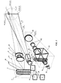
- a device for the detection of optical and optoelectronic objects 1 comprises a laser radiator 2 with a power supply unit 3, said laser radiator being optically matched with a cylindrical objective lens 4 forming a laser radiation, a strip 5 of receivers 6 of a photodetector 7, said strip being mounted to an upright position in the focal plane of a receiving channel 8, with an input objective lens 9 optically matched with inputs 10 of the receivers 6 of the strip 5 of the photodetector 7, a signal processing unit 11, a strip 12 of light indicators 13 for displaying a detected object 1, said strip being mounted on the vertical axis 14 in an image field of the surrounding area 15; each light indicator 13 of the strip 12 for displaying a detected object 1 is connected through the signal processing unit 11 and through the output 16 of the photodetector 7 to a respective group of the receivers 6 of the strip 5 of the photodetector 7 through respective outputs 17 of the receivers 6; both vertical 18 and horizontal 19 axes of an indicatrix 20 of the cylindrical objective lens 4 of the laser
- the device also comprises a sound signaling device 29 that is in electrical connection with one of outputs 30 of the signal processing unit 11.
- the device also comprises an observation system 31 made to the shape of in-series located and optically matched to each other along the aiming axis: an optico-visual observation channel 33 of an eyepiece 34, a light-splitting cube 35, a reticle 36, an optical inversion system 37 and a transmit objective lens 38; the said observation system 31 being mounted to enable an optical match between the light-splitting cube 35 and the light indicators 13 of the strip 12 for displaying a detected object 1 and a subsequent transmission of the light signal of the detection of an optical and/or optoelectronic object 1 from a respective light indicator 13 to an observer 26.
- the laser radiator 2 with the cylindrical objective lens 4 are designed to form a beam of an illuminating radiation whose indicatrix 20 takes the form of a "narrow knife” 39 (with the ratio of angular dimensions in mutually perpendicular directions equal to more than 10).
- the cylindrical objective lens 4 enables one to form the indicatrix 20 of the radiation in the form of a "narrow knife", the latter being optically matched with a vertical line of the reticle of the optico-visual observation channel 33 in the plane of locating the object 1 and having a divergence in the vertical plane, said divergence corresponding to a visual field of the optico-visual observation channel 33 and several angular minutes in the horizontal plane.
- the cylindrical objective lens is made to the shape of a cylindrical aspherical lens with an elliptical contour of the forming surface.
- the strip 5 of the receivers 6 of the photodetector 7 is designed to ensure reception of an illuminating radiation of the laser radiator 2, said radiation being re-reflected from optical and optoelectronic objects 1 and returned to a device for the detection of said optical and optoelectronic objects 1, to convert this signal into a proportional electrical signal at the output of each elementary receiver 6 of the strip 5 and to transmit the received signal to the signal processing unit 11.
- the input objective lens 9 is designed to receive radiation reflected from optical and optoelectronic objects 1 and returned to a device for the detection of said optical and optoelectronic objects 1 and to concentrate radiation on sensitive platforms of the receivers 6 of the strip 5 of the photodetector 7.
- the signal processing unit 11 is designed to receive a signal from the receivers 6 of the strip 5 of the photodetector 7, to process this signal and to warn the alarm (in the case of releasing such reflected radiation [speck of light] from optical and optoelectronic objects 1 in comparison with a background (solar, fire light, headlight, etc.)) radiation, as well as with a diffusion-reflected radiation of the laser radiator from the area of space to be radar-detected (a sector of the surrounding area 15), that is, in the detection of optical and optoelectronic objects 1 with a sound signal (with the availability of this function in the signal processing unit 11) and/or by transmitting an electrical pulse to a strip 12 of light indicators 13 for displaying a detected object 1 in order to switch a respective signaling light indicator 13 and to shape control pulses for the power supply unit 3 of the laser radiator 2 and, as a consequence, emission impulses of illumination to be shaped by the laser radiator 2.
- the strip 12 of the light indicators 13 for displaying the detected object 1 is designed to receive a signal from the signal processing unit 11, to display, by means of a light indicator 13, the detected optical and optoelectronic object 1 by transmitting a light signal of the detection of an optical or optoelectronic object 1 through a light-splitting cube 35 of an optico-visual observation channel 33 of an observation system 31 to the retina of an observer 26.
- the power supply unit 3 of the laser radiator 2 is designed to shape current supply pulses to the laser radiator 2.
- the observation system 31 is designed to view the area of space to be radar-detected (a sector of the surrounding area 15) by the observer 26, to find the position of the detected optical object 1 with the tie to an area surrounding the object 1 at the expense of superimposition on the retina of the observer 26 of an image of the area to be observed and an image of the luminous light indicator 13 of the strip 12 for displaying the detected object 1, said images being spatially correlated by means of the light-splitting cube 35 with the optico-visual observation channel 33 of the observation system 31.
- Each light indicator 13 of the strip 12 for displaying the detected object 1 is connected through the signal processing unit 11 and through the output 16 of the photodetector 7 to a respective group of the receivers 6 of the strip 5 of the photodetector 7, respective outputs 17 of said receivers 6 being connected to the output 16 of the photodetector 7.
- the power supply unit 3 When feeding a primary power, the power supply unit 3 carries out quasi-continuous feeding of the laser radiator 2, which generates a frequency train of emission impulses with the emission wavelength of 0.8-1 ⁇ m.
- the area of space to be radar-detected (a sector of the surrounding area 15), where an optical or optoelectronic object 1 to be detected is present, is irradiated with the quasi-continuous radiation of the laser radiator 2 with a high repetition rate, for example 500 Hz.
- the cylindrical objective lens 4 provides the generation of the illuminating laser radiation from the laser radiator 2 as a beam with the indicatrix 20 in the form of a "narrow knife" 39.
- the vertical axis 18 of the radiation indicatrix 20 coincides with the vertical axis 21 of the optico-visual observation channel 33 of the observation system 31.
- the detection of optical and optoelectronic objects is carried out by scanning with an aiming axis 32 of the observation system 31 a selected area of space (a sector of the surrounding area 15) in the azimuth plane (including manually).
- the availability of the laser radiation with the indicatrix 20 in the form of a "knife" 39 makes it possible to detect objects 1 performing counter observation and aiming which have come in the scanning into the view of a respective receiver 6 of the strip 5 of the photodetector 7 and are located along the entire depth of the area of space to be radar-detected (a sector of the surrounding area 15).
- the object 1 reflects the radiation with a complex indicatrix having, however, a high reverse directivity toward the radiation source to be determined mainly by elements mounted in focal planes or nearby.
- the input objective lens 9 forms am image of projection of the area of space to be radar-detected (a sector of the surrounding area 15), which is projected on optical inputs located in the vicinity of the focal point of the input objective lens 9, or directly on photosensitive elements of respective receivers 6 of the strip 5 of the photodetector 7 (a linear a multiple-unit receiver) mounted to an upright position in the focal plane of the receiving channel 8, and detected by the receivers 6 of the strip 5 of the photodetector 7, while generating at the output of respective receivers 6 of the strip 5 of the photodetector 7 an electrical signal, said signal being proportional to intensity of the radiation reflected from optical and optoelectronic objects 1 and other objects of the surrounding area 15 in the area of space to be radar-detected (a sector of the surrounding area 15) .
- the strip 5 of the receivers 6 of the photodetector 7 is mounted in the focal plane of the receiving channel 8 and optically matched with the indicatrix 20 of radiation of the laser radiator 2 (that is, a visual field of the receiving channel 8 corresponds to the indicatrix 20 of radiation of the laser radiator 2).
- optical and optoelectronic objects 1 to be detected are located, as a rule, in the plane of an angle of elevation close to the skyline. That is why, to improve the efficiency of searching the aforementioned objects 1, it is advisable to perform scanning with the device for the detection of optical and optoelectronic objects in the azimuth plane; in so doing, a preferred orientation of the indicatrix 20 of radiation of the laser radiator 2 relative to the earth is vertical.
- a visual field of the linear receiver in the plane of an angle of elevation should be no less than 3°-4° with a high repetition rate of pulses of the illuminating radiation of the laser radiator 2, for example 500-1,000 Hz.
- a major factor that increases a signal-to-noise ratio at the input of a single-unit receiver 6 is a combined use of the radiator with a knife-shaped indicatrix and the strip 5 of the receivers 6 of the photodetector 7. This affords an increase in the concentration of the illuminating radiation of the laser radiator 2 within the limits of a "narrow knife", which amplifiers the reflection of radiation by an optical and optoelectronic object 1 that has found itself in the field of illumination.
- a spurious solar radiation for example, with its availability in the day-time
- reflected from the underlying surface decreases with the square of the number of receivers 6.
- Signals from the output of respective receivers 6 of the strip 5 of the photodetector 7 arrive at the signal processing unit 11, which provides for the isolation of the radiation (speck of light) reflected from the input optics of optical and optoelectronic objects 1 from a background radiation of other objects sector of the surrounding area 15 in the area of space to be radar-detected (a sector of the surrounding area 15).
- the isolation of the radiation (speck of light) reflected from optical and optoelectronic objects 1 in comparison with a background (solar, fire light, headlight, etc.) radiation, as well as with a diffusion-reflected radiation of the laser radiator from the surrounding area 15 is available by the fact that the received light signal within the receivers 6 of the strip 5 of the photodetector 7 is converted into the electrical signal and supplied in succession to an intensity threshold device where it is processed by digital filters and where it is compared with a threshold signal (set at the level of electrical signals coming from false targets - a false reflected radiation (false specks of light)), which affords the isolation of a valid signal arriving at a respective separate receiver 6 against a background of the underlying surface and the formation of code for displaying the position of the detected object 1 for the signal processing unit 11, as well as a signal for producing a sound signal to attract the operator's attention.
- a threshold signal set at the level of electrical signals coming from false targets - a false reflected radiation (false
- an "alarm" signal according to which the electrical signal is transmitted to the sound signaling device 29 (with the availability of this function in the signal processing unit 11), which warns the observer 26 of the detection of an optical and optoelectronic object 1 and also transmits the electrical pulse to the strip 12 of the light indicators 13 for displaying a detected object 1 in order to switch a respective signaling light indicator 13.
- the strip 12 of the light indicators 13 for displaying a detected object 1 is oriented in the vertical plane and mounted in parallel to the strip 5 of the receivers 6 of the photodetector 7.
- the number of the light indicators 13 of the strip 12 for displaying a detected object 1 corresponds to the selected angular resolution of finding the position of an optical or optoelectronic object 1 to be detected.
- an algorithm of the signal processing from the strip 5 of the receivers 6 of the photodetector 7 presupposes the breaking down the strip 5 into groups of the receivers 6 in such a way that as a signal from the object 1 enters the input of one of the receivers 6 of a respective group, the output of the signal processing unit 11 generates the electrical signal for a light indicator 13 that is spatially conjugated with this group of the receivers 6.
- An alarm signal from a respective light indicator 13 and a sound signal from the sound signaling device 29 are transmitted for the time of the order of 0.2-0.5 sec. In this time interval the observer 26 has an opportunity to react to a sound and/or light signal. For a more exact position finding of an optical or optoelectronic object 1 with its tie to the surrounding area 15, the observer 26 must change the direction of scanning. In so doing, in the repeated finding of the object 1, a sound and/or light signal of alarm will be transmitted again. After finding the position of the object 1 using a range scale marked on the instrument reticle, the observer 26 may find an approximate distance to the detected optical or optoelectronic objects 1.
- Electric power supply of the laser radiator 2 is carried out using the power supply unit 3 whose operating conditions are specified by the signal processing unit 11.
- the duration of an illuminating radiation from the radiator 2 is given to be equal to the duration of the cycle of inquiring the receivers 6 of the strip 5 of the photodetector 7.
- the input objective lens 9 of the photodetector 7 may be provided with a narrow-band interference filter 40 having a pass band of, for example 40 nm.
- the input objective lens 9 may have an automatic control to ensure the maintenance of an optimal level of the signal at the output of the receivers 6 of the strip 5 of the photodetector 7 when the signal level changes at the pupil of the objective lens 9, for example, by controlling a diaphragm 41 of the input objective lens 9.
- the reception and processing of a valid signal reflected from objects and the imaging of the area to be reconnoitered are carried out in the device for the detection of optical and optoelectronic objects 1! using two separate channels (the reception channel 8 and the optico-visual observation channel 33), which makes it possible to eliminate a reciprocal influence of conflicting factors - to ensure the normal observation of the surrounding area, there has to be a high light-gathering power of the system, whereas to receive signals particularly in the daytime, care must be taken to decrease the light-gathering power.
- Noise immunity of the device for the detection of optical and optoelectronic objects is improved at the expense of providing cutoff of the image reception of the area of space to be radar-detected (a sector of the surrounding area), said area adjoining the device for the detection of optical and optoelectronic objects and light scattering within said area makes the greatest contribution to the background.
- the efficiency of the device for the detection of optical and optoelectronic objects is improved several times at the expense of the generation, by means of a cylindrical objective lens, of a beam of illuminating radiation with an indicatrix in the form of a "knife" from the laser radiator, and of the reception, with a multiple-unit linear photodetector, of a signal reflected from the matched area illuminated with a laser radiator.
- control of the device for the detection of optical and optoelectronic objects is simplified at the expense of eliminating a considerable part of control and adjustment members.
- a reciprocal influence of conflicting factors is ruled out - to ensure the normal observation of the surrounding area, there has to be a high light-gathering power of the system, whereas to receive signals particularly in the daytime, care must be taken to decrease the light-gathering power, by allowing for the separation of the receiving and processing of a valid signal reflected from the objects and the imaging of the area to be reconnoitered: these operations are carried out using two separate channels (a reception channel and an optico-visual observation channel).
- the present invention has produced good results not only when used in the field of optoelectronic instrument manufacture, but also when applied in laser radar measuring and informational technique, in armament and combat materiel, in safeguarding systems, in particular in the process of airplane landing, mining and search-and-rescue operations, for the purposes of guarding, hunting, military engineering, in optical communication lines, etc., for the remote observation, tracking and detection of optical and optoelectronic instruments that carry out counter observation and aiming, and also as a display unit of such systems and devices when their optical and optoelectronic instruments fall within an observer's view (for example, binoculars, telescopes, photographic cameras, video cameras, motion-picture cameras, optical sights of small arms, tanks, artillery and rocket-propelled launchers, etc.), instruments for aiming, observation, reconnaissance, etc., and any other instruments provided with optical objective lenses.
- an observer's view for example, binoculars, telescopes, photographic cameras, video cameras, motion-picture cameras, optical sights of small arms,
Landscapes
- Physics & Mathematics (AREA)
- General Physics & Mathematics (AREA)
- Astronomy & Astrophysics (AREA)
- Optics & Photonics (AREA)
- Electromagnetism (AREA)
- Engineering & Computer Science (AREA)
- Remote Sensing (AREA)
- Radar, Positioning & Navigation (AREA)
- Computer Networks & Wireless Communication (AREA)
- Photo Coupler, Interrupter, Optical-To-Optical Conversion Devices (AREA)
- Optical Radar Systems And Details Thereof (AREA)
- Geophysics And Detection Of Objects (AREA)
- Burglar Alarm Systems (AREA)
- Nitrogen And Oxygen Or Sulfur-Condensed Heterocyclic Ring Systems (AREA)
- Circuit Arrangement For Electric Light Sources In General (AREA)
- Photoreceptors In Electrophotography (AREA)
- Length Measuring Devices By Optical Means (AREA)
Applications Claiming Priority (3)
| Application Number | Priority Date | Filing Date | Title |
|---|---|---|---|
| RU2002114235/09A RU2223515C1 (ru) | 2002-05-31 | 2002-05-31 | Устройство обнаружения оптических и оптико-электронных объектов |
| RU2002114235 | 2002-05-31 | ||
| PCT/RU2003/000239 WO2003102626A1 (fr) | 2002-05-31 | 2003-05-28 | Dispositif de detection d'objets optiques et optoelectroniques |
Publications (3)
| Publication Number | Publication Date |
|---|---|
| EP1515162A1 true EP1515162A1 (fr) | 2005-03-16 |
| EP1515162A4 EP1515162A4 (fr) | 2006-04-26 |
| EP1515162B1 EP1515162B1 (fr) | 2008-05-21 |
Family
ID=29707830
Family Applications (1)
| Application Number | Title | Priority Date | Filing Date |
|---|---|---|---|
| EP03741719A Expired - Lifetime EP1515162B1 (fr) | 2002-05-31 | 2003-05-28 | Dispositif de detection d'objets optiques et optoelectroniques |
Country Status (6)
| Country | Link |
|---|---|
| EP (1) | EP1515162B1 (fr) |
| AT (1) | ATE396411T1 (fr) |
| AU (1) | AU2003273489A1 (fr) |
| DE (1) | DE60321172D1 (fr) |
| RU (1) | RU2223515C1 (fr) |
| WO (1) | WO2003102626A1 (fr) |
Cited By (5)
| Publication number | Priority date | Publication date | Assignee | Title |
|---|---|---|---|---|
| WO2006045271A1 (fr) * | 2004-10-29 | 2006-05-04 | Jenoptik Laser, Optik, Systeme Gmbh | Dispositif et procede pour identifier et localiser des systemes de contre-observation optique |
| EP1688761A1 (fr) * | 2005-02-03 | 2006-08-09 | Carl Zeiss Optronics GmbH | Procédé et dispositif destinés à la découverte de systèmes optiques dans une zone de terrain |
| FR2915000A1 (fr) * | 2007-04-11 | 2008-10-17 | Cie Ind Des Lasers Cilas Sa | Procede et dispositif a un laser pour la detection de systemes optiques grossissants |
| US7456944B2 (en) | 2006-03-23 | 2008-11-25 | Carl Zeiss Optronics Gmbh | Apparatus and method for detection of optical systems in a terrain area |
| US8731240B1 (en) * | 2010-08-05 | 2014-05-20 | Lockheed Martin Corporation | System and method for optics detection |
Families Citing this family (11)
| Publication number | Priority date | Publication date | Assignee | Title |
|---|---|---|---|---|
| WO2005088380A1 (fr) * | 2004-03-11 | 2005-09-22 | Federalnoe Gosudarstvennoe Unitarnoe Predpriyatie 'osoboe Konstruktorskoe Byuro Vysokoenergetichestikh Laserov 'granat' Imeni V.K. Orlova' | Dispositif pour detecter des objets optiques ou optoelectroniques |
| RU2456746C2 (ru) * | 2009-10-14 | 2012-07-20 | Корпорация "САМСУНГ ЭЛЕКТРОНИКС Ко., Лтд." | Оптическая система связи с ножевидной подсветкой |
| RU2451397C2 (ru) * | 2009-10-14 | 2012-05-20 | Корпорация "САМСУНГ ЭЛЕКТРОНИКС Ко., Лтд." | Устройство системы оптической связи с автоматическим сопровождением светового луча на приемнике информации |
| RU2540002C1 (ru) * | 2013-06-27 | 2015-01-27 | Федеральное государственное казенное военное образовательное учреждение высшего профессионального образования "Военный учебно-научный центр Военно-воздушных сил "Военно-воздушная академия имени профессора Н.Е. Жуковского и Ю.А. Гагарина" (г. Воронеж) Министерства обороны Российской Федерации | Способ оптико-электронного наблюдения |
| RU2540001C1 (ru) * | 2013-06-28 | 2015-01-27 | Федеральное государственное казенное военное образовательное учреждение высшего профессионального образования "Военный учебно-научный центр Военно-воздушных сил "Военно-воздушная академия имени профессора Н.Е. Жуковского и Ю.А. Гагарина" (г. Воронеж) Министерства обороны Российской Федерации | Способ адаптивного оптико-электронного наблюдения |
| RU2536768C1 (ru) * | 2013-07-29 | 2014-12-27 | Закрытое акционерное общество "ВНИИРА-Навигатор" | Способ инерциально-спутниковой навигации летательных аппаратов |
| RU2540447C1 (ru) * | 2013-10-11 | 2015-02-10 | Открытое акционерное общество "НПО "Геофизика-НВ" | Способ контроля степени адаптации светотехнического оборудования и контрольно-проверочный прибор |
| RU2642336C2 (ru) * | 2015-11-23 | 2018-01-24 | Федеральное государственное бюджетное образовательное учреждение высшего профессионального образования "Ижевский государственный технический университет имени М.Т. Калашникова" | Система защиты охраняемой территории |
| RU2663121C1 (ru) * | 2016-11-28 | 2018-08-07 | Публичное акционерное общество "Ракетно-космическая корпорация "Энергия" имени С.П. Королева" | Оптическая система формирования и наведения лазерного излучения |
| RU2706912C9 (ru) * | 2016-12-16 | 2020-01-16 | Федеральное государственное унитарное предприятие Государственный научно-исследовательский институт авиационных систем | Способ адаптивного сканирования подстилающей поверхности лучом лазерного локатора в режиме информационного обеспечения маловысотного полета |
| RU188539U1 (ru) * | 2018-12-10 | 2019-04-16 | Федеральное государственное бюджетное учреждение науки Институт оптики атмосферы им. В.Е. Зуева Сибирского отделения Российской академии наук (ИОА СО РАН) | Лазерное устройство видения |
Citations (2)
| Publication number | Priority date | Publication date | Assignee | Title |
|---|---|---|---|---|
| GB2174862A (en) * | 1985-04-24 | 1986-11-12 | Eltro Gmbh | Harmonying the optical axes of combined heat imaging apparatus and sight |
| US4902128A (en) * | 1983-08-16 | 1990-02-20 | Hughes Aircraft Company | Apparatus for harmonizing a plurality of optical/optronic axis of sighting apparatus to a common axis |
Family Cites Families (4)
| Publication number | Priority date | Publication date | Assignee | Title |
|---|---|---|---|---|
| JP2523633B2 (ja) * | 1987-05-13 | 1996-08-14 | 株式会社日立製作所 | レ−ザレ−ダの走査方法 |
| US5270795A (en) * | 1992-08-11 | 1993-12-14 | National Research Council Of Canada/Conseil National De Rechereches Du Canada | Validation of optical ranging of a target surface in a cluttered environment |
| RU2059961C1 (ru) * | 1992-10-21 | 1996-05-10 | Научно-Производственное Объединение "Геофизика" | Стабилизированное тепловизионное устройство наведения |
| RU2155357C1 (ru) * | 1999-06-15 | 2000-08-27 | Государственное унитарное предприятие "НПО Астрофизика" | Способ обнаружения оптических и оптико-электронных приборов |
-
2002
- 2002-05-31 RU RU2002114235/09A patent/RU2223515C1/ru not_active IP Right Cessation
-
2003
- 2003-05-28 EP EP03741719A patent/EP1515162B1/fr not_active Expired - Lifetime
- 2003-05-28 DE DE60321172T patent/DE60321172D1/de not_active Expired - Fee Related
- 2003-05-28 AU AU2003273489A patent/AU2003273489A1/en not_active Abandoned
- 2003-05-28 AT AT03741719T patent/ATE396411T1/de not_active IP Right Cessation
- 2003-05-28 WO PCT/RU2003/000239 patent/WO2003102626A1/fr not_active Application Discontinuation
Patent Citations (2)
| Publication number | Priority date | Publication date | Assignee | Title |
|---|---|---|---|---|
| US4902128A (en) * | 1983-08-16 | 1990-02-20 | Hughes Aircraft Company | Apparatus for harmonizing a plurality of optical/optronic axis of sighting apparatus to a common axis |
| GB2174862A (en) * | 1985-04-24 | 1986-11-12 | Eltro Gmbh | Harmonying the optical axes of combined heat imaging apparatus and sight |
Non-Patent Citations (1)
| Title |
|---|
| See also references of WO03102626A1 * |
Cited By (7)
| Publication number | Priority date | Publication date | Assignee | Title |
|---|---|---|---|---|
| WO2006045271A1 (fr) * | 2004-10-29 | 2006-05-04 | Jenoptik Laser, Optik, Systeme Gmbh | Dispositif et procede pour identifier et localiser des systemes de contre-observation optique |
| EP1688761A1 (fr) * | 2005-02-03 | 2006-08-09 | Carl Zeiss Optronics GmbH | Procédé et dispositif destinés à la découverte de systèmes optiques dans une zone de terrain |
| US7456944B2 (en) | 2006-03-23 | 2008-11-25 | Carl Zeiss Optronics Gmbh | Apparatus and method for detection of optical systems in a terrain area |
| FR2915000A1 (fr) * | 2007-04-11 | 2008-10-17 | Cie Ind Des Lasers Cilas Sa | Procede et dispositif a un laser pour la detection de systemes optiques grossissants |
| WO2008142269A2 (fr) * | 2007-04-11 | 2008-11-27 | Compagnie Industrielle Des Lasers Cilas | Procédé et dispositif à un laser pour la détection de systèmes optiques grossissants |
| WO2008142269A3 (fr) * | 2007-04-11 | 2009-01-22 | Cilas | Procédé et dispositif à un laser pour la détection de systèmes optiques grossissants |
| US8731240B1 (en) * | 2010-08-05 | 2014-05-20 | Lockheed Martin Corporation | System and method for optics detection |
Also Published As
| Publication number | Publication date |
|---|---|
| EP1515162A4 (fr) | 2006-04-26 |
| AU2003273489A1 (en) | 2003-12-19 |
| WO2003102626A1 (fr) | 2003-12-11 |
| ATE396411T1 (de) | 2008-06-15 |
| EP1515162B1 (fr) | 2008-05-21 |
| RU2223515C1 (ru) | 2004-02-10 |
| DE60321172D1 (de) | 2008-07-03 |
Similar Documents
| Publication | Publication Date | Title |
|---|---|---|
| EP1515162B1 (fr) | Dispositif de detection d'objets optiques et optoelectroniques | |
| Repasi et al. | Advanced short-wavelength infrared range-gated imaging for ground applications in monostatic and bistatic configurations | |
| US4277170A (en) | Laser beacon and optical detector system for aircraft collision hazard determination | |
| US8451432B2 (en) | Laser spot tracking with off-axis angle detection | |
| CN111344647A (zh) | 具有低延时运动规划更新的智能激光雷达系统 | |
| US7773202B2 (en) | Laser spot tracker and target identifier | |
| US7164468B2 (en) | Lidar system controlled by computer for smoke identification applied, in particular, to early stage forest fire detection | |
| US20050094134A1 (en) | Method and apparatus for detecting a moving projectile | |
| US4836672A (en) | Covert optical system for probing and inhibiting remote targets | |
| CN108693516B (zh) | 一种快速测量激光测距系统性能的装置及方法 | |
| KR20140090065A (ko) | 레이저 검출 및 경고 시스템 | |
| US20140009611A1 (en) | Camera System and Method for Observing Objects at Great Distances, in Particular for Monitoring Target Objects at Night, in Mist, Dust or Rain | |
| CN108931783B (zh) | 一种高精度测量激光测距系统性能的装置及方法 | |
| WO2002021641A2 (fr) | Systeme radar passif couple en signalisation a un systeme radar actif | |
| RU2113717C1 (ru) | Лазерная система обнаружения оптоэлектронных объектов | |
| EP3535604B1 (fr) | Système et procédé destinés à un pointeur caché/des communications cachées et télémètre laser | |
| US5677761A (en) | Passive ranging to source of known spectral emission | |
| RU2540154C2 (ru) | Устройство обнаружения оптических и оптико-электронных приборов | |
| Mohamed et al. | A novel dichroic beam splitters and sky cameras-based LIDAR receiver | |
| RU191986U1 (ru) | Прицел-дальномер малогабаритный | |
| AU779584B2 (en) | In-action boresight | |
| RU139683U1 (ru) | Оптико-электронная система боевого беспилотного летательного аппарата | |
| Seidel et al. | Novel approaches to helicopter obstacle warning | |
| RU148255U1 (ru) | Лазерная оптико-локационная станция | |
| US5449899A (en) | Apparatus and method for highlighting returns from optically augmented targets |
Legal Events
| Date | Code | Title | Description |
|---|---|---|---|
| PUAI | Public reference made under article 153(3) epc to a published international application that has entered the european phase |
Free format text: ORIGINAL CODE: 0009012 |
|
| 17P | Request for examination filed |
Effective date: 20041222 |
|
| AK | Designated contracting states |
Kind code of ref document: A1 Designated state(s): AT BE BG CH CY CZ DE DK EE ES FI FR GB GR HU IE IT LI LU MC NL PT RO SE SI SK TR |
|
| AX | Request for extension of the european patent |
Extension state: AL LT LV MK |
|
| DAX | Request for extension of the european patent (deleted) | ||
| A4 | Supplementary search report drawn up and despatched |
Effective date: 20060315 |
|
| 17Q | First examination report despatched |
Effective date: 20070417 |
|
| GRAP | Despatch of communication of intention to grant a patent |
Free format text: ORIGINAL CODE: EPIDOSNIGR1 |
|
| GRAS | Grant fee paid |
Free format text: ORIGINAL CODE: EPIDOSNIGR3 |
|
| GRAA | (expected) grant |
Free format text: ORIGINAL CODE: 0009210 |
|
| AK | Designated contracting states |
Kind code of ref document: B1 Designated state(s): AT BE BG CH CY CZ DE DK EE ES FI FR GB GR HU IE IT LI LU MC NL PT RO SE SI SK TR |
|
| REG | Reference to a national code |
Ref country code: GB Ref legal event code: FG4D |
|
| REG | Reference to a national code |
Ref country code: CH Ref legal event code: EP |
|
| REF | Corresponds to: |
Ref document number: 60321172 Country of ref document: DE Date of ref document: 20080703 Kind code of ref document: P |
|
| REG | Reference to a national code |
Ref country code: IE Ref legal event code: FG4D |
|
| PG25 | Lapsed in a contracting state [announced via postgrant information from national office to epo] |
Ref country code: SI Free format text: LAPSE BECAUSE OF FAILURE TO SUBMIT A TRANSLATION OF THE DESCRIPTION OR TO PAY THE FEE WITHIN THE PRESCRIBED TIME-LIMIT Effective date: 20080521 |
|
| PG25 | Lapsed in a contracting state [announced via postgrant information from national office to epo] |
Ref country code: FI Free format text: LAPSE BECAUSE OF FAILURE TO SUBMIT A TRANSLATION OF THE DESCRIPTION OR TO PAY THE FEE WITHIN THE PRESCRIBED TIME-LIMIT Effective date: 20080521 Ref country code: ES Free format text: LAPSE BECAUSE OF FAILURE TO SUBMIT A TRANSLATION OF THE DESCRIPTION OR TO PAY THE FEE WITHIN THE PRESCRIBED TIME-LIMIT Effective date: 20080901 |
|
| PGFP | Annual fee paid to national office [announced via postgrant information from national office to epo] |
Ref country code: DE Payment date: 20080724 Year of fee payment: 6 |
|
| NLV1 | Nl: lapsed or annulled due to failure to fulfill the requirements of art. 29p and 29m of the patents act | ||
| PG25 | Lapsed in a contracting state [announced via postgrant information from national office to epo] |
Ref country code: NL Free format text: LAPSE BECAUSE OF FAILURE TO SUBMIT A TRANSLATION OF THE DESCRIPTION OR TO PAY THE FEE WITHIN THE PRESCRIBED TIME-LIMIT Effective date: 20080521 Ref country code: AT Free format text: LAPSE BECAUSE OF FAILURE TO SUBMIT A TRANSLATION OF THE DESCRIPTION OR TO PAY THE FEE WITHIN THE PRESCRIBED TIME-LIMIT Effective date: 20080521 |
|
| PGFP | Annual fee paid to national office [announced via postgrant information from national office to epo] |
Ref country code: FR Payment date: 20080626 Year of fee payment: 6 |
|
| PG25 | Lapsed in a contracting state [announced via postgrant information from national office to epo] |
Ref country code: MC Free format text: LAPSE BECAUSE OF NON-PAYMENT OF DUE FEES Effective date: 20080531 |
|
| PGFP | Annual fee paid to national office [announced via postgrant information from national office to epo] |
Ref country code: GB Payment date: 20080716 Year of fee payment: 6 |
|
| REG | Reference to a national code |
Ref country code: CH Ref legal event code: PL |
|
| PG25 | Lapsed in a contracting state [announced via postgrant information from national office to epo] |
Ref country code: CZ Free format text: LAPSE BECAUSE OF FAILURE TO SUBMIT A TRANSLATION OF THE DESCRIPTION OR TO PAY THE FEE WITHIN THE PRESCRIBED TIME-LIMIT Effective date: 20080521 Ref country code: SE Free format text: LAPSE BECAUSE OF FAILURE TO SUBMIT A TRANSLATION OF THE DESCRIPTION OR TO PAY THE FEE WITHIN THE PRESCRIBED TIME-LIMIT Effective date: 20080821 Ref country code: CH Free format text: LAPSE BECAUSE OF NON-PAYMENT OF DUE FEES Effective date: 20080531 Ref country code: LI Free format text: LAPSE BECAUSE OF NON-PAYMENT OF DUE FEES Effective date: 20080531 Ref country code: DK Free format text: LAPSE BECAUSE OF FAILURE TO SUBMIT A TRANSLATION OF THE DESCRIPTION OR TO PAY THE FEE WITHIN THE PRESCRIBED TIME-LIMIT Effective date: 20080521 Ref country code: PT Free format text: LAPSE BECAUSE OF FAILURE TO SUBMIT A TRANSLATION OF THE DESCRIPTION OR TO PAY THE FEE WITHIN THE PRESCRIBED TIME-LIMIT Effective date: 20081021 |
|
| REG | Reference to a national code |
Ref country code: IE Ref legal event code: MM4A |
|
| PG25 | Lapsed in a contracting state [announced via postgrant information from national office to epo] |
Ref country code: SK Free format text: LAPSE BECAUSE OF FAILURE TO SUBMIT A TRANSLATION OF THE DESCRIPTION OR TO PAY THE FEE WITHIN THE PRESCRIBED TIME-LIMIT Effective date: 20080521 Ref country code: BE Free format text: LAPSE BECAUSE OF FAILURE TO SUBMIT A TRANSLATION OF THE DESCRIPTION OR TO PAY THE FEE WITHIN THE PRESCRIBED TIME-LIMIT Effective date: 20080521 Ref country code: RO Free format text: LAPSE BECAUSE OF FAILURE TO SUBMIT A TRANSLATION OF THE DESCRIPTION OR TO PAY THE FEE WITHIN THE PRESCRIBED TIME-LIMIT Effective date: 20080521 |
|
| PLBE | No opposition filed within time limit |
Free format text: ORIGINAL CODE: 0009261 |
|
| STAA | Information on the status of an ep patent application or granted ep patent |
Free format text: STATUS: NO OPPOSITION FILED WITHIN TIME LIMIT |
|
| 26N | No opposition filed |
Effective date: 20090224 |
|
| PG25 | Lapsed in a contracting state [announced via postgrant information from national office to epo] |
Ref country code: EE Free format text: LAPSE BECAUSE OF FAILURE TO SUBMIT A TRANSLATION OF THE DESCRIPTION OR TO PAY THE FEE WITHIN THE PRESCRIBED TIME-LIMIT Effective date: 20080521 Ref country code: BG Free format text: LAPSE BECAUSE OF FAILURE TO SUBMIT A TRANSLATION OF THE DESCRIPTION OR TO PAY THE FEE WITHIN THE PRESCRIBED TIME-LIMIT Effective date: 20080821 Ref country code: IE Free format text: LAPSE BECAUSE OF NON-PAYMENT OF DUE FEES Effective date: 20080528 |
|
| PG25 | Lapsed in a contracting state [announced via postgrant information from national office to epo] |
Ref country code: IT Free format text: LAPSE BECAUSE OF FAILURE TO SUBMIT A TRANSLATION OF THE DESCRIPTION OR TO PAY THE FEE WITHIN THE PRESCRIBED TIME-LIMIT Effective date: 20080521 |
|
| GBPC | Gb: european patent ceased through non-payment of renewal fee |
Effective date: 20090528 |
|
| REG | Reference to a national code |
Ref country code: FR Ref legal event code: ST Effective date: 20100129 |
|
| PG25 | Lapsed in a contracting state [announced via postgrant information from national office to epo] |
Ref country code: FR Free format text: LAPSE BECAUSE OF NON-PAYMENT OF DUE FEES Effective date: 20090602 |
|
| PG25 | Lapsed in a contracting state [announced via postgrant information from national office to epo] |
Ref country code: GB Free format text: LAPSE BECAUSE OF NON-PAYMENT OF DUE FEES Effective date: 20090528 |
|
| PG25 | Lapsed in a contracting state [announced via postgrant information from national office to epo] |
Ref country code: DE Free format text: LAPSE BECAUSE OF NON-PAYMENT OF DUE FEES Effective date: 20091201 |
|
| PG25 | Lapsed in a contracting state [announced via postgrant information from national office to epo] |
Ref country code: CY Free format text: LAPSE BECAUSE OF FAILURE TO SUBMIT A TRANSLATION OF THE DESCRIPTION OR TO PAY THE FEE WITHIN THE PRESCRIBED TIME-LIMIT Effective date: 20080521 Ref country code: HU Free format text: LAPSE BECAUSE OF FAILURE TO SUBMIT A TRANSLATION OF THE DESCRIPTION OR TO PAY THE FEE WITHIN THE PRESCRIBED TIME-LIMIT Effective date: 20081122 Ref country code: LU Free format text: LAPSE BECAUSE OF NON-PAYMENT OF DUE FEES Effective date: 20080528 |
|
| PG25 | Lapsed in a contracting state [announced via postgrant information from national office to epo] |
Ref country code: TR Free format text: LAPSE BECAUSE OF FAILURE TO SUBMIT A TRANSLATION OF THE DESCRIPTION OR TO PAY THE FEE WITHIN THE PRESCRIBED TIME-LIMIT Effective date: 20080521 |
|
| PG25 | Lapsed in a contracting state [announced via postgrant information from national office to epo] |
Ref country code: GR Free format text: LAPSE BECAUSE OF FAILURE TO SUBMIT A TRANSLATION OF THE DESCRIPTION OR TO PAY THE FEE WITHIN THE PRESCRIBED TIME-LIMIT Effective date: 20080822 |