EP1686600A2 - 2-poliger Umschalter - Google Patents
2-poliger Umschalter Download PDFInfo
- Publication number
- EP1686600A2 EP1686600A2 EP06001831A EP06001831A EP1686600A2 EP 1686600 A2 EP1686600 A2 EP 1686600A2 EP 06001831 A EP06001831 A EP 06001831A EP 06001831 A EP06001831 A EP 06001831A EP 1686600 A2 EP1686600 A2 EP 1686600A2
- Authority
- EP
- European Patent Office
- Prior art keywords
- circuit
- contacts
- switching contact
- contact
- switch according
- Prior art date
- Legal status (The legal status is an assumption and is not a legal conclusion. Google has not performed a legal analysis and makes no representation as to the accuracy of the status listed.)
- Granted
Links
- 238000004519 manufacturing process Methods 0.000 description 2
- 229910000639 Spring steel Inorganic materials 0.000 description 1
- 239000004020 conductor Substances 0.000 description 1
- 238000010276 construction Methods 0.000 description 1
- 230000001419 dependent effect Effects 0.000 description 1
- 230000007704 transition Effects 0.000 description 1
Images


Classifications
-
- H—ELECTRICITY
- H01—ELECTRIC ELEMENTS
- H01H—ELECTRIC SWITCHES; RELAYS; SELECTORS; EMERGENCY PROTECTIVE DEVICES
- H01H13/00—Switches having rectilinearly-movable operating part or parts adapted for pushing or pulling in one direction only, e.g. push-button switch
- H01H13/02—Details
- H01H13/26—Snap-action arrangements depending upon deformation of elastic members
- H01H13/36—Snap-action arrangements depending upon deformation of elastic members using flexing of blade springs
- H01H13/38—Single blade moved across dead-centre position
-
- H—ELECTRICITY
- H01—ELECTRIC ELEMENTS
- H01H—ELECTRIC SWITCHES; RELAYS; SELECTORS; EMERGENCY PROTECTIVE DEVICES
- H01H13/00—Switches having rectilinearly-movable operating part or parts adapted for pushing or pulling in one direction only, e.g. push-button switch
- H01H13/02—Details
- H01H13/26—Snap-action arrangements depending upon deformation of elastic members
-
- H—ELECTRICITY
- H01—ELECTRIC ELEMENTS
- H01H—ELECTRIC SWITCHES; RELAYS; SELECTORS; EMERGENCY PROTECTIVE DEVICES
- H01H13/00—Switches having rectilinearly-movable operating part or parts adapted for pushing or pulling in one direction only, e.g. push-button switch
- H01H13/50—Switches having rectilinearly-movable operating part or parts adapted for pushing or pulling in one direction only, e.g. push-button switch having a single operating member
- H01H13/52—Switches having rectilinearly-movable operating part or parts adapted for pushing or pulling in one direction only, e.g. push-button switch having a single operating member the contact returning to its original state immediately upon removal of operating force, e.g. bell-push switch
-
- H—ELECTRICITY
- H01—ELECTRIC ELEMENTS
- H01H—ELECTRIC SWITCHES; RELAYS; SELECTORS; EMERGENCY PROTECTIVE DEVICES
- H01H1/00—Contacts
- H01H2001/0005—Redundant contact pairs in one switch for safety reasons
-
- H—ELECTRICITY
- H01—ELECTRIC ELEMENTS
- H01H—ELECTRIC SWITCHES; RELAYS; SELECTORS; EMERGENCY PROTECTIVE DEVICES
- H01H2225/00—Switch site location
- H01H2225/014—Switch site location normally closed combined with normally open
Definitions
- the invention relates to a switch for switching two circuits.
- Such switches can be used in particular in motor vehicles, for example as NO / NC change or double switch.
- the known from the prior art constructions are relatively expensive.
- the object of the invention is to provide a switch, which is characterized by particularly low manufacturing costs, redundancy and reliability and the ability to simultaneously switch two independent circuits such that at least one contact pair closes and opens a pair of contacts simultaneously.
- a switch for switching two circuits comprising a housing, a plunger, two contacts of a first circuit, two contacts of a second circuit and a switching contact having a first shape in the initial state, in which the first circuit is closed and the second circuit is opened, and can be brought by actuation of the plunger in a second form in which the first circuit is opened and the second circuit is closed.
- the switch according to the invention is based on the idea, with a and to switch the same switching contact two different circuits and to use the transition of the switching contact from a first mold into a second mold to close the contacts of a first circuit and to open the contacts of a second circuit. Since only a single switching contact is required for this, results in a simple structure that pulls low production costs.
- FIGS. 1 and 2 show a change-over switch 10 which has a housing 12 in which four contacts 1, 2, 3 and 4 to be switched are accommodated.
- a plunger 14 is slidably mounted in the housing 12.
- the plunger 14 cooperates with a switching contact 16, which can open or close the electrical contact between the two contacts 1, 2, which form a first circuit, and the two contacts 3, 4, which form a second circuit.
- the switching contact 16 is made of spring steel sheet or other elastically resilient and electrically conductive material and has a generally rectangular basic shape (see Figure 3). Considered in a plane containing the contacts 3 and 4 (view of Figures 1 and 5), the switching contact 16 is curved in the initial state to the plunger 14 out; it has the form of a snap spring. At the short side edges of the generally rectangular body of the switching contact 16 retaining tabs 18 are provided by means of which the switching contact is mounted on the housing 12. In each case between two adjacent retaining tabs 18 extends outwardly in each case a contact tab 20, which is formed here in each case 3 individual tabs (see Figure 3).
- the contact tabs 20 are located on the contacts 3 and 4; the circuit through the contacts 3 and 4 is thus closed (see also Figure 4).
- the switching contact 16 has an approximately planar shape. Starting from the longer side edges of the rectangular main body of the switching contact 16 contact tabs 22 which are associated with the two first contacts 1, 2 and also consist of several individual tabs. In the initial state, that is, when the plunger 14 is not actuated, the contact tabs 22 are at a distance from the first contacts 1, 2; the first circuit formed by these contacts is thus open.
- the plunger 14 When the plunger 14 is actuated, it presses on the center of the arcuate switching contact 16. This is converted from its first shape, which is shown in FIGS. 5 and 6 with solid lines, into a second shape, which is shown in FIGS Figures 5 and 6 is shown in dashed lines.
- the switching contact 16 against the retaining force acting from the retaining tabs 18, snaps over a dead center down, so that the contact tabs 20 are lifted from the contacts 3, 4; the second circuit formed by these contacts is thus opened (see the state of the switching contact 16 shown in dashed lines in FIG. 5).
- the switching contact 16 in the contacts 1, 2 containing plane is displaced substantially translationally down, so that the contact tabs 22 rest on the contacts 1, 2; the first circuit formed by these is thus closed.
- the switching contact 16 snaps back into its first form, in which the first circuit formed by the contacts 1, 2 is opened and the second circuit formed by the contacts 3, 4 is closed.
- FIG. 8 shows a variant embodiment which differs from the first embodiment due to the deviating configuration of the contact lugs 20, 22.
- each two opposing contact tabs 22 are used, which are each formed here of four individual tabs.
- each two contact tabs 20 are used, which lie on one side and the other side of the respective retaining tab 18.
- Each contact tab 20 in turn consists of several individual tabs. In this way, a greater contact reliability results in the contact.
- FIGS. 9 and 10 show a changeover switch according to a second embodiment. This differs from the switch according to the first embodiment in that below the switching contact 16, a second switching contact 16 'is arranged. With regard to its shape and its function, the second switching contact 16 'corresponds to the first switching contact 16 with the difference that the second switching contact 16' is made smaller, so that it fits under the switching contact 16. It is actuated by an extension 30 formed on the plunger 14, which extends through the switching contact 16 and on the second switching contact 16 'attacks. In this way, twice the number of contacts can be switched at the same time.
Landscapes
- Push-Button Switches (AREA)
- Driving Mechanisms And Operating Circuits Of Arc-Extinguishing High-Tension Switches (AREA)
- Coupling Device And Connection With Printed Circuit (AREA)
- Fittings On The Vehicle Exterior For Carrying Loads, And Devices For Holding Or Mounting Articles (AREA)
- Keying Circuit Devices (AREA)
- Breakers (AREA)
- Slide Switches (AREA)
- Switches That Are Operated By Magnetic Or Electric Fields (AREA)
- Electronic Switches (AREA)
- Rotary Switch, Piano Key Switch, And Lever Switch (AREA)
Abstract
Description
- Die Erfindung betrifft einen Umschalter zum Schalten von zwei Stromkreisen.
- Solche Umschalter können insbesondere bei Kraftfahrzeugen eingesetzt werden, beispielsweise als Schließer-/Öffner-Wechsel oder Doppelschalter. Die aus dem Stand der Technik bekannten Konstruktionen sind jedoch vergleichsweise aufwendig.
- Die Aufgabe der Erfindung besteht darin, einen Umschalter zu schaffen, der sich durch besonders geringe Herstellungskosten, Redundanz und Zuverlässigkeit sowie die Möglichkeit auszeichnet, zwei unabhängige Schaltkreise gleichzeitig derart zu schalten, daß mindestens ein Kontaktpaar schließt und ein Kontaktpaar gleichzeitig öffnet.
- Zur Lösung dieser Aufgabe ist erfindungsgemäß ein Umschalter zum Schalten von zwei Stromkreisen vorgesehen, mit einem Gehäuse, einem Stößel, zwei Kontakten eines ersten Stromkreises, zwei Kontakten eines zweiten Stromkreises und einem Schaltkontakt, der im Ausgangszustand eine erste Form aufweist, in welcher der erste Stromkreis geschlossen ist und der zweite Stromkreis geöffnet ist, und durch Betätigung des Stößels in eine zweite Form gebracht werden kann, in welcher der erste Stromkreis geöffnet und der zweite Stromkreis geschlossen ist. Der erfindungsgemäße Umschalter basiert auf dem Grundgedanken, mit ein und demselben Schaltkontakt zwei verschiedene Stromkreise zu schalten und den Übergang des Schaltkontaktes von einer ersten Form in eine zweite Form dazu zu nutzen, die Kontakte eines ersten Stromkreises zu schließen und die Kontakte eines zweiten Stromkreises zu öffnen. Da lediglich ein einziger Schaltkontakt hierfür erforderlich ist, ergibt sich ein einfacher Aufbau, der geringe Herstellungskosten nach sich zieht.
- Vorteilhafte Ausgestaltungen der Erfindung ergeben sich aus den Unteransprüchen.
- Die Erfindung wird nachfolgend anhand einer bevorzugten Ausführungsform beschrieben, die in den beigefügten Zeichnungen dargestellt ist. In diesen zeigen:
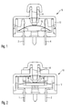
- Figur 1 einen schematischen Schnitt durch einen erfindungsgemäßen Umschalter;
- Figur 2 einen um 90° gedrehten Schnitt durch den Umschalter von Figur 1;
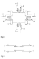
- Figur 3 schematisch die vom Umschalter geschalteten Kontakte;
- Figur 4 eine weitere schematische Ansicht der geschalteten Kontakte;
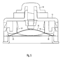
- Figur 5 in vergrößertem Maßstab die Ansicht von Figur 1;
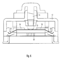
- Figur 6 in vergrößertem Maßstab die Ansicht von Figur 2;
- Figur 7 in vergrößertem Maßstab die Ansicht von Figur 3;
- Figur 8 in einer Ansicht entsprechend derjenigen von Figur 7 eine Ausführungsvariante;
- Figur 9 in einer Ansicht entsprechend derjenigen von Figur 5 einen Umschalter gemäß einer zweiten Ausführungsform; und
- Figur 10 den Umschalter gemäß der zweiten Ausführungsform in einer Ansicht entsprechend derjenigen von Figur 6.
- In den Figuren 1 und 2 ist ein Umschalter 10 zu sehen, der ein Gehäuse 12 aufweist, in welchem vier zu schaltende Kontakte 1, 2, 3 und 4 aufgenommen sind. Im Gehäuse 12 ist ein Stößel 14 verschiebbar angebracht. Der Stößel 14 wirkt mit einem Schaltkontakt 16 zusammen, der den elektrischen Kontakt zwischen den beiden Kontakten 1, 2, die einen ersten Stromkreis bilden, und den beiden Kontakten 3, 4, die einen zweiten Stromkreis bilden, öffnen oder schließen kann.
- Der Schaltkontakt 16 besteht aus Federblech oder einem anderen elastisch federnden und elektrisch leitenden Material und hat eine allgemein rechteckige Grundform (siehe Figur 3). Betrachtet in einer Ebene, welche die Kontakte 3 und 4 enthält (Darstellung der Figuren 1 und 5) ist der Schaltkontakt 16 im Ausgangszustand zum Stößel 14 hin gewölbt; er hat die Form einer Schnappfeder. An den kurzen Seitenrändem des allgemein rechteckigen Grundkörpers des Schaltkontaktes 16 sind Haltelaschen 18 vorgesehen, mittels denen der Schaltkontakt am Gehäuse 12 angebracht ist. Jeweils zwischen zwei benachbarten Haltelaschen 18 erstreckt sich nach außen jeweils eine Kontaktlasche 20, die hier aus jeweils 3 Einzellaschen gebildet ist (siehe Figur 3). In der in den Figuren 1 und 5 gezeigten Ausgangsstellung, also bei nicht betätigtem Stößel 14, liegen die Kontaktlaschen 20 an den Kontakten 3 und 4 an; der Stromkreis durch die Kontakte 3 und 4 ist also geschlossen (siehe auch Figur 4). In einer durch die Kontakte 1 und 2 führenden Ebene (siehe die Figuren 2 und 6) hat der Schaltkontakt 16 eine etwa ebene Form. Ausgehend von den längeren Seitenrändern des rechteckigen Grundkörpers des Schaltkontakts 16 erstrecken sich Kontaktlaschen 22, die den beiden ersten Kontakten 1, 2 zugeordnet sind und ebenfalls aus mehreren Einzellaschen bestehen. Im Ausgangszustand, also bei nicht betätigtem Stößel 14, befinden sich die Kontaktlaschen 22 im Abstand von den ersten Kontakten 1, 2; der von diesen Kontakten gebildete erste Stromkreis ist also geöffnet.
- Wenn der Stößel 14 betätigt wird, drückt er auf die Mitte des bogenförmigen Schaltkontakts 16. Dieser wird aus seiner ersten Form, die in den Figuren 5 und 6 mit durchgezogenen Linien gezeigt ist, in eine zweite Form überführt, die in den Figuren 5 und 6 gestrichelt gezeigt ist. In der die Kontakte 3, 4 enthaltenden Ebene schnappt der Schaltkontakt 16, entgegen der von den Haltelaschen 18 wirkenden Haltekraft, über einen Totpunkt hinweg nach unten, so daß die Kontaktlaschen 20 von den Kontakten 3, 4 abgehoben werden; der von diesen Kontakten gebildete zweite Stromkreis wird somit geöffnet (siehe den in Figur 5 gestrichelt gezeigten Zustand des Schaltkontakts 16). Gleichzeitig wird der Schaltkontakt 16 in der die Kontakte 1, 2 enthaltenden Ebene im wesentlichen translatorisch nach unten verstellt, so daß die Kontaktlaschen 22 auf den Kontakten 1, 2 aufliegen; der von diesen gebildete erste Stromkreis wird somit geschlossen.
- Wenn der Stößel 14 wieder freigegeben wird, schnappt der Schaltkontakt 16 wieder zurück in seine erste Form, in welcher der von den Kontakten 1, 2 gebildete erste Stromkreis geöffnet und der von den Kontakten 3, 4 gebildete zweite Stromkreis geschlossen ist.
- In Figur 8 ist eine Ausführungsvariante dargestellt, die sich durch die abweichende Ausgestaltung der Kontaktlaschen 20, 22 von der ersten Ausführungsform unterscheidet. Für die Kontakte 1, 2 werden jeweils zwei einander gegenüberliegende Kontaktlaschen 22 verwendet, die hier aus jeweils vier Einzellaschen gebildet sind. Für die Kontakte 3, 4 werden jeweils zwei Kontaktlaschen 20 verwendet, die auf der einen und der anderen Seite der jeweiligen Haltelasche 18 liegen. Jede Kontaktlasche 20 besteht wiederum aus mehreren Einzellaschen. Auf diese Weise ergibt sich eine größere Kontaktsicherheit bei der Kontaktierung.
- In den Figuren 9 und 10 ist ein Umschalter gemäß einer zweiten Ausführungsform gezeigt. Dieser unterscheidet sich von dem Umschalter gemäß der ersten Ausführungsform dadurch, daß unterhalb des Schaltkontaktes 16 ein zweiter Schaltkontakt 16' angeordnet ist. Hinsichtlich seiner Form und seiner Funktion entspricht der zweite Schaltkontakt 16' dem ersten Schaltkontakt 16 mit dem Unterschied, daß der zweite Schaltkontakt 16' verkleinert ausgeführt ist, so daß er unter den Schaltkontakt 16 paßt. Er wird betätigt durch einen am Stößel 14 ausgebildeten Fortsatz 30, der sich durch den Schaltkontakt 16 hindurch erstreckt und am zweiten Schaltkontakt 16' angreift. Auf diese Weise kann gleichzeitig die doppelte Anzahl von Kontakten geschaltet werden.
Claims (11)
- Umschalter zum Schalten von zwei Stromkreisen, mit einem Gehäuse (12), einem Stößel (14), zwei Kontakten (1, 2) eines ersten Stromkreises, zwei Kontakten (3, 4) eines zweiten Stromkreises und einem Schaltkontakt (16), der im Ausgangszustand eine erste Form aufweist, in welcher der erste Stromkreis geschlossen und der zweite Stromkreis geöffnet ist, und durch Betätigung des Stößels (14) in eine zweite Form gebracht werden kann, in welcher der erste Stromkreis geöffnet und der zweite Stromkreis geschlossen ist.
- Umschalter nach Anspruch 1, dadurch gekennzeichnet, daß der Schaltkontakt (16) in einer Ebene, in der die beiden Kontakte (1, 2) des ersten Stromkreises liegen, im Ausgangszustand eine zum Stößel (14) gewölbte Form aufweist.
- Umschalter nach Anspruch 2, dadurch gekennzeichnet, daß der Schaltkontakt (16) in der Ebene, in der die beiden Kontakte (3, 4) des zweiten Stromkreises liegen, nach Art einer Schnappfeder ausgebildet ist, die aus dem Ausgangszustand über einen Totpunkt in die zweite Form schnappen kann.
- Umschalter nach Anspruch 2 oder Anspruch 3, dadurch gekennzeichnet, daß der Schaltkontakt (16) durch Haltelaschen (18), die in der Ebene der beiden Kontakte (3, 4) des zweiten Stromkreises liegen, am Gehäuse (12) angebracht ist.
- Umschalter nach Anspruch 4, dadurch gekennzeichnet, daß der Schaltkontakt mit zwei ersten Kontaktlaschen (20) versehen sind, die radial betrachtet außerhalb der beiden Haltelaschen (18) liegen.
- Umschalter nach Anspruch 5, dadurch gekennzeichnet, daß die beiden ersten Kontaktlaschen (20) bei Betätigung des Stößels von den beiden Kontakten (3, 4) des zweiten Stromkreises abgehoben werden.
- Umschalter nach einem der vorhergehenden Ansprüche, dadurch gekennzeichnet, daß der Schaltkontakt (16) in einer Ebene, in der die beiden Kontakte (1, 2) des ersten Stromkreises liegen, im Ausgangszustand eine im wesentlichen ebene Form aufweist.
- Umschalter nach Anspruch 7, dadurch gekennzeichnet, daß der Schaltkontakt (16) in der Ebene, in der die beiden Kontakte (1, 2) des ersten Stromkreises liegen, durch Einwirkung des Stößels (14) im wesentlichen translatorisch bewegt wird.
- Umschalter nach Anspruch 7 oder Anspruch 8, dadurch gekennzeichnet, daß der Schaltkontakt (16) zwei zweite Kontaktlaschen (22) aufweist, die bei Betätigung des Stößels (14) auf die beiden Kontakte des ersten Stromkreises gedrückt werden.
- Umschalter nach einem der Ansprüche 5, 6 und 9, dadurch gekennzeichnet, daß die Kontaktlaschen (20, 22) aus mehreren Einzellaschen bestehen.
- Umschalter nach einem der vorhergehenden Ansprüche, dadurch gekennzeichnet, daß in der Betätigungsrichtung des Stößels (14) betrachtet hinter dem Schaltkontakt (16) ein zweiter Schaltkontakt (16') angeordnet ist.
Priority Applications (1)
| Application Number | Priority Date | Filing Date | Title |
|---|---|---|---|
| PL06001831T PL1686600T3 (pl) | 2005-01-31 | 2006-01-30 | Przełącznik dwubiegunowy |
Applications Claiming Priority (1)
| Application Number | Priority Date | Filing Date | Title |
|---|---|---|---|
| DE200520001495 DE202005001495U1 (de) | 2005-01-31 | 2005-01-31 | 2-poliger Umschalter |
Publications (3)
| Publication Number | Publication Date |
|---|---|
| EP1686600A2 true EP1686600A2 (de) | 2006-08-02 |
| EP1686600A3 EP1686600A3 (de) | 2007-08-01 |
| EP1686600B1 EP1686600B1 (de) | 2009-02-25 |
Family
ID=34673377
Family Applications (1)
| Application Number | Title | Priority Date | Filing Date |
|---|---|---|---|
| EP06001831A Expired - Lifetime EP1686600B1 (de) | 2005-01-31 | 2006-01-30 | 2-poliger Umschalter |
Country Status (9)
| Country | Link |
|---|---|
| US (1) | US7667153B2 (de) |
| EP (1) | EP1686600B1 (de) |
| JP (1) | JP4365374B2 (de) |
| CN (1) | CN100454459C (de) |
| AT (1) | ATE424033T1 (de) |
| BR (1) | BRPI0600171B1 (de) |
| DE (2) | DE202005001495U1 (de) |
| ES (1) | ES2321747T3 (de) |
| PL (1) | PL1686600T3 (de) |
Families Citing this family (5)
| Publication number | Priority date | Publication date | Assignee | Title |
|---|---|---|---|---|
| JP4371987B2 (ja) * | 2004-12-07 | 2009-11-25 | ホシデン株式会社 | プッシュオンスイッチ |
| US20090033521A1 (en) * | 2007-08-01 | 2009-02-05 | Ladouceur Norman M | Key designs for compact keypad of handheld communication device |
| JP5554983B2 (ja) * | 2009-12-22 | 2014-07-23 | キヤノン株式会社 | 電子機器 |
| CN105551896B (zh) * | 2015-12-22 | 2018-07-27 | 厦门宏发电力电器有限公司 | 一种接触组件及其高压直流继电器 |
| JP6588832B2 (ja) * | 2016-01-14 | 2019-10-09 | 東京パーツ工業株式会社 | ドアハンドル装置 |
Citations (1)
| Publication number | Priority date | Publication date | Assignee | Title |
|---|---|---|---|---|
| US2526850A (en) | 1947-01-20 | 1950-10-24 | Cutler Hammer Inc | Snap switch |
Family Cites Families (14)
| Publication number | Priority date | Publication date | Assignee | Title |
|---|---|---|---|---|
| DE1091179B (de) * | 1956-11-28 | 1960-10-20 | Haegglund & Soener Ab | Elektrischer Schnappschalter mit Kontaktbruecke |
| US3736395A (en) * | 1971-02-03 | 1973-05-29 | E Miller | Direct-action switch |
| DE2360167A1 (de) * | 1973-12-03 | 1975-06-05 | Marquardt J & J | Schalter |
| DE7441251U (de) | 1974-12-11 | 1975-04-30 | Kirsten F Elektrotechnische Spezial | Druckschalter für Kraftfahrzeuge, insbesondere Bremslichtschalter |
| DE2730659C2 (de) * | 1977-07-07 | 1979-04-26 | Standard Elektrik Lorenz Ag, 7000 Stuttgart | Tastschalter |
| DE2740875A1 (de) | 1977-09-10 | 1979-03-29 | Marquardt J & J | Elektrischer schalter |
| DE3012107A1 (de) | 1980-03-28 | 1981-10-08 | Olympia Werke Ag, 2940 Wilhelmshaven | Drucktastenschalter |
| US5343008A (en) * | 1992-02-19 | 1994-08-30 | Ipcinski Ralph G | Sealed switch |
| DE4233447C1 (de) | 1992-10-05 | 1994-01-27 | Barlian Reinhold | Schalteinrichtung |
| JP3746374B2 (ja) * | 1998-05-26 | 2006-02-15 | アルプス電気株式会社 | 多方向入力装置 |
| JP2004031171A (ja) | 2002-06-26 | 2004-01-29 | Smk Corp | 2段動作プッシュスイッチ |
| CN2643462Y (zh) * | 2003-09-16 | 2004-09-22 | 林锡埼 | 二段式触压开关 |
| JP4503424B2 (ja) * | 2004-11-30 | 2010-07-14 | アルプス電気株式会社 | 多段スイッチ装置 |
| JP4446925B2 (ja) * | 2005-04-28 | 2010-04-07 | ホシデン株式会社 | スライド操作式スイッチ |
-
2005
- 2005-01-31 DE DE200520001495 patent/DE202005001495U1/de not_active Expired - Lifetime
-
2006
- 2006-01-24 CN CNB200610006039XA patent/CN100454459C/zh not_active Expired - Fee Related
- 2006-01-25 US US11/339,131 patent/US7667153B2/en not_active Expired - Fee Related
- 2006-01-25 BR BRPI0600171-8A patent/BRPI0600171B1/pt not_active IP Right Cessation
- 2006-01-27 JP JP2006018378A patent/JP4365374B2/ja not_active Expired - Fee Related
- 2006-01-30 DE DE502006002918T patent/DE502006002918D1/de not_active Expired - Lifetime
- 2006-01-30 AT AT06001831T patent/ATE424033T1/de not_active IP Right Cessation
- 2006-01-30 ES ES06001831T patent/ES2321747T3/es not_active Expired - Lifetime
- 2006-01-30 PL PL06001831T patent/PL1686600T3/pl unknown
- 2006-01-30 EP EP06001831A patent/EP1686600B1/de not_active Expired - Lifetime
Patent Citations (1)
| Publication number | Priority date | Publication date | Assignee | Title |
|---|---|---|---|---|
| US2526850A (en) | 1947-01-20 | 1950-10-24 | Cutler Hammer Inc | Snap switch |
Also Published As
| Publication number | Publication date |
|---|---|
| ES2321747T3 (es) | 2009-06-10 |
| EP1686600B1 (de) | 2009-02-25 |
| BRPI0600171B1 (pt) | 2017-07-04 |
| EP1686600A3 (de) | 2007-08-01 |
| US7667153B2 (en) | 2010-02-23 |
| US20060180453A1 (en) | 2006-08-17 |
| CN1819088A (zh) | 2006-08-16 |
| PL1686600T3 (pl) | 2009-09-30 |
| BRPI0600171A (pt) | 2006-09-19 |
| CN100454459C (zh) | 2009-01-21 |
| JP2006216545A (ja) | 2006-08-17 |
| ATE424033T1 (de) | 2009-03-15 |
| JP4365374B2 (ja) | 2009-11-18 |
| DE502006002918D1 (de) | 2009-04-09 |
| DE202005001495U1 (de) | 2005-06-09 |
Similar Documents
| Publication | Publication Date | Title |
|---|---|---|
| DE60007537T2 (de) | Verbesserter elektroschalter mit fühlbarem effekt und einen einzigen schaltglied | |
| EP0131304B1 (de) | Schiebeschalter | |
| DE102010045629A1 (de) | Einreihige NOT-AUS-Schalter-Kontaktvorrichtung | |
| DE1172757B (de) | Elektrischer Tuerschalter | |
| DE19538767A1 (de) | Schalter mit flexibler Leiterfolie als ortsfester Kontakt und Verbindung zu Anschlußkontakten | |
| DE1920784A1 (de) | Schiebeschalter fuer Geraete mit einem von einer Isolierstoffplatte getragenen Leiternetz | |
| EP1686600B1 (de) | 2-poliger Umschalter | |
| DE2439697A1 (de) | Druckschalter | |
| EP1764813B1 (de) | Elektrischer Schalter | |
| DE2705756A1 (de) | Druckknopfschalter fuer elektronische tischrechner o.dgl. | |
| DE60030934T2 (de) | Anordnung zur verstärkung des hubs eines betätigungsorgans eines schalters | |
| DE102017130199B4 (de) | Folienwandler, Ventil, Pumpe sowie Verfahren zum Betreiben einer Pumpe | |
| EP1869688B1 (de) | Mehrpoliges schaltgerät mit zusatzgehäuse und gegenseitige mechanische verriegelungs vorrichtung | |
| DE10255617A1 (de) | Fassung für elektrische Bauteile | |
| EP1467390A1 (de) | Tastenblock zum Einsetzen in eine Bedienfläche eines Haushaltsgerätes | |
| EP0021413A1 (de) | Gabelumschalter für Fernsprechapparate | |
| DE202019001525U1 (de) | Elektrischer Schalter | |
| DE102013000904A1 (de) | Elektrischer Schalter mit einer Schaltkontaktfeder und Schaltkontaktfeder | |
| EP0602462B1 (de) | Elektrisches Schaltgerät | |
| DE102011056333A1 (de) | Elektrischer Schalter | |
| DE3137749C2 (de) | ||
| DE2462035C3 (de) | Tastatur | |
| DE2064706C3 (de) | Schaltelement für Niederspannung, insbesondere für den Zusammenbau zu einem Paketschalter | |
| DE102005054266B3 (de) | Schaltfeld | |
| DE19700125C2 (de) | Mehrpolige Schaltvorrichtung |
Legal Events
| Date | Code | Title | Description |
|---|---|---|---|
| PUAI | Public reference made under article 153(3) epc to a published international application that has entered the european phase |
Free format text: ORIGINAL CODE: 0009012 |
|
| AK | Designated contracting states |
Kind code of ref document: A2 Designated state(s): AT BE BG CH CY CZ DE DK EE ES FI FR GB GR HU IE IS IT LI LT LU LV MC NL PL PT RO SE SI SK TR |
|
| AX | Request for extension of the european patent |
Extension state: AL BA HR MK YU |
|
| PUAL | Search report despatched |
Free format text: ORIGINAL CODE: 0009013 |
|
| AK | Designated contracting states |
Kind code of ref document: A3 Designated state(s): AT BE BG CH CY CZ DE DK EE ES FI FR GB GR HU IE IS IT LI LT LU LV MC NL PL PT RO SE SI SK TR |
|
| AX | Request for extension of the european patent |
Extension state: AL BA HR MK YU |
|
| RIC1 | Information provided on ipc code assigned before grant |
Ipc: H01H 13/26 20060101ALI20070627BHEP Ipc: H01H 13/38 20060101ALI20070627BHEP Ipc: H01H 13/52 20060101AFI20070627BHEP |
|
| 17P | Request for examination filed |
Effective date: 20080104 |
|
| 17Q | First examination report despatched |
Effective date: 20080206 |
|
| AKX | Designation fees paid |
Designated state(s): AT BE BG CH CY CZ DE DK EE ES FI FR GB GR HU IE IS IT LI LT LU LV MC NL PL PT RO SE SI SK TR |
|
| GRAP | Despatch of communication of intention to grant a patent |
Free format text: ORIGINAL CODE: EPIDOSNIGR1 |
|
| GRAS | Grant fee paid |
Free format text: ORIGINAL CODE: EPIDOSNIGR3 |
|
| GRAA | (expected) grant |
Free format text: ORIGINAL CODE: 0009210 |
|
| AK | Designated contracting states |
Kind code of ref document: B1 Designated state(s): AT BE BG CH CY CZ DE DK EE ES FI FR GB GR HU IE IS IT LI LT LU LV MC NL PL PT RO SE SI SK TR |
|
| REG | Reference to a national code |
Ref country code: GB Ref legal event code: FG4D Free format text: NOT ENGLISH |
|
| REG | Reference to a national code |
Ref country code: CH Ref legal event code: EP |
|
| RAP2 | Party data changed (patent owner data changed or rights of a patent transferred) |
Owner name: TRW AUTOMOTIVE ELECTRONICS & COMPONENTS GMBH |
|
| REG | Reference to a national code |
Ref country code: IE Ref legal event code: FG4D Free format text: LANGUAGE OF EP DOCUMENT: GERMAN |
|
| REF | Corresponds to: |
Ref document number: 502006002918 Country of ref document: DE Date of ref document: 20090409 Kind code of ref document: P |
|
| NLT2 | Nl: modifications (of names), taken from the european patent patent bulletin |
Owner name: TRW AUTOMOTIVE ELECTRONICS & COMPONENTS GMBH Effective date: 20090325 |
|
| REG | Reference to a national code |
Ref country code: ES Ref legal event code: FG2A Ref document number: 2321747 Country of ref document: ES Kind code of ref document: T3 |
|
| PG25 | Lapsed in a contracting state [announced via postgrant information from national office to epo] |
Ref country code: FI Free format text: LAPSE BECAUSE OF FAILURE TO SUBMIT A TRANSLATION OF THE DESCRIPTION OR TO PAY THE FEE WITHIN THE PRESCRIBED TIME-LIMIT Effective date: 20090225 Ref country code: LT Free format text: LAPSE BECAUSE OF FAILURE TO SUBMIT A TRANSLATION OF THE DESCRIPTION OR TO PAY THE FEE WITHIN THE PRESCRIBED TIME-LIMIT Effective date: 20090225 Ref country code: NL Free format text: LAPSE BECAUSE OF FAILURE TO SUBMIT A TRANSLATION OF THE DESCRIPTION OR TO PAY THE FEE WITHIN THE PRESCRIBED TIME-LIMIT Effective date: 20090225 Ref country code: SI Free format text: LAPSE BECAUSE OF FAILURE TO SUBMIT A TRANSLATION OF THE DESCRIPTION OR TO PAY THE FEE WITHIN THE PRESCRIBED TIME-LIMIT Effective date: 20090225 |
|
| NLV1 | Nl: lapsed or annulled due to failure to fulfill the requirements of art. 29p and 29m of the patents act | ||
| PG25 | Lapsed in a contracting state [announced via postgrant information from national office to epo] |
Ref country code: IS Free format text: LAPSE BECAUSE OF FAILURE TO SUBMIT A TRANSLATION OF THE DESCRIPTION OR TO PAY THE FEE WITHIN THE PRESCRIBED TIME-LIMIT Effective date: 20090625 Ref country code: LV Free format text: LAPSE BECAUSE OF FAILURE TO SUBMIT A TRANSLATION OF THE DESCRIPTION OR TO PAY THE FEE WITHIN THE PRESCRIBED TIME-LIMIT Effective date: 20090225 Ref country code: SE Free format text: LAPSE BECAUSE OF FAILURE TO SUBMIT A TRANSLATION OF THE DESCRIPTION OR TO PAY THE FEE WITHIN THE PRESCRIBED TIME-LIMIT Effective date: 20090525 |
|
| REG | Reference to a national code |
Ref country code: IE Ref legal event code: FD4D |
|
| REG | Reference to a national code |
Ref country code: PL Ref legal event code: T3 |
|
| PG25 | Lapsed in a contracting state [announced via postgrant information from national office to epo] |
Ref country code: DK Free format text: LAPSE BECAUSE OF FAILURE TO SUBMIT A TRANSLATION OF THE DESCRIPTION OR TO PAY THE FEE WITHIN THE PRESCRIBED TIME-LIMIT Effective date: 20090225 Ref country code: IE Free format text: LAPSE BECAUSE OF FAILURE TO SUBMIT A TRANSLATION OF THE DESCRIPTION OR TO PAY THE FEE WITHIN THE PRESCRIBED TIME-LIMIT Effective date: 20090225 Ref country code: PT Free format text: LAPSE BECAUSE OF FAILURE TO SUBMIT A TRANSLATION OF THE DESCRIPTION OR TO PAY THE FEE WITHIN THE PRESCRIBED TIME-LIMIT Effective date: 20090812 Ref country code: EE Free format text: LAPSE BECAUSE OF FAILURE TO SUBMIT A TRANSLATION OF THE DESCRIPTION OR TO PAY THE FEE WITHIN THE PRESCRIBED TIME-LIMIT Effective date: 20090225 |
|
| PG25 | Lapsed in a contracting state [announced via postgrant information from national office to epo] |
Ref country code: SK Free format text: LAPSE BECAUSE OF FAILURE TO SUBMIT A TRANSLATION OF THE DESCRIPTION OR TO PAY THE FEE WITHIN THE PRESCRIBED TIME-LIMIT Effective date: 20090225 Ref country code: RO Free format text: LAPSE BECAUSE OF FAILURE TO SUBMIT A TRANSLATION OF THE DESCRIPTION OR TO PAY THE FEE WITHIN THE PRESCRIBED TIME-LIMIT Effective date: 20090225 |
|
| PLBE | No opposition filed within time limit |
Free format text: ORIGINAL CODE: 0009261 |
|
| STAA | Information on the status of an ep patent application or granted ep patent |
Free format text: STATUS: NO OPPOSITION FILED WITHIN TIME LIMIT |
|
| PG25 | Lapsed in a contracting state [announced via postgrant information from national office to epo] |
Ref country code: BG Free format text: LAPSE BECAUSE OF FAILURE TO SUBMIT A TRANSLATION OF THE DESCRIPTION OR TO PAY THE FEE WITHIN THE PRESCRIBED TIME-LIMIT Effective date: 20090525 |
|
| 26N | No opposition filed |
Effective date: 20091126 |
|
| PGFP | Annual fee paid to national office [announced via postgrant information from national office to epo] |
Ref country code: PL Payment date: 20091209 Year of fee payment: 5 |
|
| BERE | Be: lapsed |
Owner name: TRW AUTOMOTIVE ELECTRONICS & COMPONENTS G.M.B.H. Effective date: 20100131 |
|
| PG25 | Lapsed in a contracting state [announced via postgrant information from national office to epo] |
Ref country code: MC Free format text: LAPSE BECAUSE OF NON-PAYMENT OF DUE FEES Effective date: 20100131 |
|
| REG | Reference to a national code |
Ref country code: CH Ref legal event code: PL |
|
| GBPC | Gb: european patent ceased through non-payment of renewal fee |
Effective date: 20100130 |
|
| REG | Reference to a national code |
Ref country code: FR Ref legal event code: ST Effective date: 20100930 |
|
| PG25 | Lapsed in a contracting state [announced via postgrant information from national office to epo] |
Ref country code: FR Free format text: LAPSE BECAUSE OF NON-PAYMENT OF DUE FEES Effective date: 20100201 Ref country code: GR Free format text: LAPSE BECAUSE OF FAILURE TO SUBMIT A TRANSLATION OF THE DESCRIPTION OR TO PAY THE FEE WITHIN THE PRESCRIBED TIME-LIMIT Effective date: 20090526 Ref country code: LI Free format text: LAPSE BECAUSE OF NON-PAYMENT OF DUE FEES Effective date: 20100131 Ref country code: CH Free format text: LAPSE BECAUSE OF NON-PAYMENT OF DUE FEES Effective date: 20100131 |
|
| PG25 | Lapsed in a contracting state [announced via postgrant information from national office to epo] |
Ref country code: CZ Free format text: LAPSE BECAUSE OF NON-PAYMENT OF DUE FEES Effective date: 20100130 |
|
| PG25 | Lapsed in a contracting state [announced via postgrant information from national office to epo] |
Ref country code: GB Free format text: LAPSE BECAUSE OF NON-PAYMENT OF DUE FEES Effective date: 20100130 |
|
| PG25 | Lapsed in a contracting state [announced via postgrant information from national office to epo] |
Ref country code: BE Free format text: LAPSE BECAUSE OF NON-PAYMENT OF DUE FEES Effective date: 20100131 |
|
| REG | Reference to a national code |
Ref country code: ES Ref legal event code: FD2A Effective date: 20110224 |
|
| PG25 | Lapsed in a contracting state [announced via postgrant information from national office to epo] |
Ref country code: IT Free format text: LAPSE BECAUSE OF NON-PAYMENT OF DUE FEES Effective date: 20100130 |
|
| PG25 | Lapsed in a contracting state [announced via postgrant information from national office to epo] |
Ref country code: ES Free format text: LAPSE BECAUSE OF NON-PAYMENT OF DUE FEES Effective date: 20110223 |
|
| PG25 | Lapsed in a contracting state [announced via postgrant information from national office to epo] |
Ref country code: ES Free format text: LAPSE BECAUSE OF NON-PAYMENT OF DUE FEES Effective date: 20100131 |
|
| REG | Reference to a national code |
Ref country code: AT Ref legal event code: MM01 Ref document number: 424033 Country of ref document: AT Kind code of ref document: T Effective date: 20110130 |
|
| PG25 | Lapsed in a contracting state [announced via postgrant information from national office to epo] |
Ref country code: CY Free format text: LAPSE BECAUSE OF FAILURE TO SUBMIT A TRANSLATION OF THE DESCRIPTION OR TO PAY THE FEE WITHIN THE PRESCRIBED TIME-LIMIT Effective date: 20090225 Ref country code: PL Free format text: LAPSE BECAUSE OF NON-PAYMENT OF DUE FEES Effective date: 20110130 |
|
| REG | Reference to a national code |
Ref country code: PL Ref legal event code: LAPE |
|
| PG25 | Lapsed in a contracting state [announced via postgrant information from national office to epo] |
Ref country code: LU Free format text: LAPSE BECAUSE OF NON-PAYMENT OF DUE FEES Effective date: 20100130 Ref country code: HU Free format text: LAPSE BECAUSE OF FAILURE TO SUBMIT A TRANSLATION OF THE DESCRIPTION OR TO PAY THE FEE WITHIN THE PRESCRIBED TIME-LIMIT Effective date: 20090826 |
|
| PG25 | Lapsed in a contracting state [announced via postgrant information from national office to epo] |
Ref country code: TR Free format text: LAPSE BECAUSE OF FAILURE TO SUBMIT A TRANSLATION OF THE DESCRIPTION OR TO PAY THE FEE WITHIN THE PRESCRIBED TIME-LIMIT Effective date: 20090225 |
|
| PG25 | Lapsed in a contracting state [announced via postgrant information from national office to epo] |
Ref country code: AT Free format text: LAPSE BECAUSE OF NON-PAYMENT OF DUE FEES Effective date: 20110130 |
|
| PGFP | Annual fee paid to national office [announced via postgrant information from national office to epo] |
Ref country code: DE Payment date: 20190121 Year of fee payment: 14 |
|
| REG | Reference to a national code |
Ref country code: DE Ref legal event code: R082 Ref document number: 502006002918 Country of ref document: DE Representative=s name: PRINZ & PARTNER MBB PATENTANWAELTE RECHTSANWAE, DE Ref country code: DE Ref legal event code: R081 Ref document number: 502006002918 Country of ref document: DE Owner name: BCS AUTOMOTIVE INTERFACE SOLUTIONS GMBH, DE Free format text: FORMER OWNER: TRW AUTOMOTIVE ELECTRONICS & COMPONENTS GMBH, 78315 RADOLFZELL, DE |
|
| REG | Reference to a national code |
Ref country code: DE Ref legal event code: R119 Ref document number: 502006002918 Country of ref document: DE |
|
| PG25 | Lapsed in a contracting state [announced via postgrant information from national office to epo] |
Ref country code: DE Free format text: LAPSE BECAUSE OF NON-PAYMENT OF DUE FEES Effective date: 20200801 |