EP1686243B1 - Stator de turbine avec des alliages à mémoire de forme et pilotage de jeu des aubes - Google Patents
Stator de turbine avec des alliages à mémoire de forme et pilotage de jeu des aubes Download PDFInfo
- Publication number
- EP1686243B1 EP1686243B1 EP06250412.1A EP06250412A EP1686243B1 EP 1686243 B1 EP1686243 B1 EP 1686243B1 EP 06250412 A EP06250412 A EP 06250412A EP 1686243 B1 EP1686243 B1 EP 1686243B1
- Authority
- EP
- European Patent Office
- Prior art keywords
- sma
- gap
- engine operation
- fluid
- shroud
- Prior art date
- Legal status (The legal status is an assumption and is not a legal conclusion. Google has not performed a legal analysis and makes no representation as to the accuracy of the status listed.)
- Not-in-force
Links
- 229910001285 shape-memory alloy Inorganic materials 0.000 title claims description 51
- 239000012530 fluid Substances 0.000 claims description 39
- 230000008859 change Effects 0.000 claims description 9
- 238000000034 method Methods 0.000 claims description 8
- 239000003570 air Substances 0.000 description 11
- 229910045601 alloy Inorganic materials 0.000 description 7
- 239000000956 alloy Substances 0.000 description 7
- 230000000712 assembly Effects 0.000 description 7
- 238000000429 assembly Methods 0.000 description 7
- 230000007704 transition Effects 0.000 description 5
- 239000012080 ambient air Substances 0.000 description 3
- 238000001816 cooling Methods 0.000 description 3
- 238000002485 combustion reaction Methods 0.000 description 2
- 238000010438 heat treatment Methods 0.000 description 2
- 239000000463 material Substances 0.000 description 2
- 230000007246 mechanism Effects 0.000 description 2
- 239000000203 mixture Substances 0.000 description 2
- 239000007787 solid Substances 0.000 description 2
- 229910000990 Ni alloy Inorganic materials 0.000 description 1
- HZEWFHLRYVTOIW-UHFFFAOYSA-N [Ti].[Ni] Chemical compound [Ti].[Ni] HZEWFHLRYVTOIW-UHFFFAOYSA-N 0.000 description 1
- 230000001133 acceleration Effects 0.000 description 1
- 238000000137 annealing Methods 0.000 description 1
- 230000008602 contraction Effects 0.000 description 1
- 239000000284 extract Substances 0.000 description 1
- 239000000446 fuel Substances 0.000 description 1
- 230000006870 function Effects 0.000 description 1
- 238000004519 manufacturing process Methods 0.000 description 1
- 229910001092 metal group alloy Inorganic materials 0.000 description 1
- 230000004048 modification Effects 0.000 description 1
- 238000012986 modification Methods 0.000 description 1
- 229910001000 nickel titanium Inorganic materials 0.000 description 1
- HLXZNVUGXRDIFK-UHFFFAOYSA-N nickel titanium Chemical compound [Ti].[Ti].[Ti].[Ti].[Ti].[Ti].[Ti].[Ti].[Ti].[Ti].[Ti].[Ni].[Ni].[Ni].[Ni].[Ni].[Ni].[Ni].[Ni].[Ni].[Ni].[Ni].[Ni].[Ni].[Ni] HLXZNVUGXRDIFK-UHFFFAOYSA-N 0.000 description 1
- 229910052758 niobium Inorganic materials 0.000 description 1
- 230000003068 static effect Effects 0.000 description 1
- 229910052715 tantalum Inorganic materials 0.000 description 1
- 230000010512 thermal transition Effects 0.000 description 1
Images


Classifications
-
- F—MECHANICAL ENGINEERING; LIGHTING; HEATING; WEAPONS; BLASTING
- F01—MACHINES OR ENGINES IN GENERAL; ENGINE PLANTS IN GENERAL; STEAM ENGINES
- F01D—NON-POSITIVE DISPLACEMENT MACHINES OR ENGINES, e.g. STEAM TURBINES
- F01D11/00—Preventing or minimising internal leakage of working-fluid, e.g. between stages
- F01D11/08—Preventing or minimising internal leakage of working-fluid, e.g. between stages for sealing space between rotor blade tips and stator
- F01D11/14—Adjusting or regulating tip-clearance, i.e. distance between rotor-blade tips and stator casing
- F01D11/16—Adjusting or regulating tip-clearance, i.e. distance between rotor-blade tips and stator casing by self-adjusting means
- F01D11/18—Adjusting or regulating tip-clearance, i.e. distance between rotor-blade tips and stator casing by self-adjusting means using stator or rotor components with predetermined thermal response, e.g. selective insulation, thermal inertia, differential expansion
-
- F—MECHANICAL ENGINEERING; LIGHTING; HEATING; WEAPONS; BLASTING
- F01—MACHINES OR ENGINES IN GENERAL; ENGINE PLANTS IN GENERAL; STEAM ENGINES
- F01D—NON-POSITIVE DISPLACEMENT MACHINES OR ENGINES, e.g. STEAM TURBINES
- F01D11/00—Preventing or minimising internal leakage of working-fluid, e.g. between stages
- F01D11/08—Preventing or minimising internal leakage of working-fluid, e.g. between stages for sealing space between rotor blade tips and stator
- F01D11/14—Adjusting or regulating tip-clearance, i.e. distance between rotor-blade tips and stator casing
- F01D11/20—Actively adjusting tip-clearance
- F01D11/24—Actively adjusting tip-clearance by selectively cooling-heating stator or rotor components
-
- F—MECHANICAL ENGINEERING; LIGHTING; HEATING; WEAPONS; BLASTING
- F05—INDEXING SCHEMES RELATING TO ENGINES OR PUMPS IN VARIOUS SUBCLASSES OF CLASSES F01-F04
- F05D—INDEXING SCHEME FOR ASPECTS RELATING TO NON-POSITIVE-DISPLACEMENT MACHINES OR ENGINES, GAS-TURBINES OR JET-PROPULSION PLANTS
- F05D2300/00—Materials; Properties thereof
- F05D2300/50—Intrinsic material properties or characteristics
- F05D2300/505—Shape memory behaviour
Definitions
- This invention relates generally to turbine engine stator assemblies, and more particularly, to apparatus and method for controlling operating clearance between a stationary shroud surface in a turbine engine stator assembly and a rotating surface of juxtaposed blading members.
- Forms of an axial flow turbine engine include rotating assemblies radially within stationary assemblies that assist in defining a flowpath of the engine.
- Examples include a rotary compressor assembly that compresses incoming air, and a rotary turbine assembly that extracts power from products of engine fuel combustion.
- Such assemblies comprise stages of rotating blades within a surrounding stator assembly that includes a shroud surface spaced apart from cooperating surfaces of the rotating blades.
- Efficiency of a turbine engine depends, at least in part, on the clearance or gap between the juxtaposed shroud surface and the rotating blades. If the clearance is excessive, undesirable leakage of engine flowpath fluid will occur between such gap resulting in reduced engine efficiency. If the clearance is too small, interference can occur between the rotating and stationary members of such assemblies, resulting in damage to one or more of such cooperating surfaces.
- Complicating clearance problems in such apparatus is the well known fact that clearance between such turbine engine assemblies changes with engine operating conditions such as acceleration, deceleration, or other changing thermal or centrifugal force conditions experienced by the cooperating members during engine operation.
- Clearance control mechanisms for such assemblies sometimes referred to as active clearance control systems, have included mechanical systems or systems based on thermal expansion and contraction characteristics of materials for the purpose of maintaining selected clearance conditions during engine operation. Such systems generally require use of substantial amounts of air for heating or cooling at the expense of such air otherwise being used in the engine operating cycle. Examples of clearance control mechanisms can be found in EP 1467066 and US 2002/0001519 . Provision of an improved means for active clearance control that reduces the need for engine flowpath fluid for such heating or cooling could enhance engine efficiency.
- One form of the present invention which is defined in claim 1, comprises a turbine engine stator assembly circumferentially spaced apart about a turbine engine rotary blading assembly across a gap having a first radial gap length prior to engine operation.
- the stator assembly comprises a circumferential shroud having an inner shroud surface defining a first radial boundary of the gap and the rotary blading assembly comprises blading members having an outer blading member surface defining a second radial boundary of the gap.
- the stator assembly includes a shroud that is movable radially, at least one gap control member made of a shape memory alloy (SMA), and fluid flow means to deliver fluid, for example air, at pre-selected temperatures to the SMA of the gap control member.
- SMA of the gap control member is selected and preconditioned to deform pre-selected amounts during engine operation, responsive to temperature of the fluid, to move the inner shroud surface radially in relation to the outer blading member surface to change the first radial gap length pre-selected amounts during turbine engine operation.
- the present invention provides a method for varying the radial length of a gap between a circumferentially stationary surface, for example the shroud inner surface, and a circumferentially rotating surface, for example the outer blading member surface.
- a form of the method comprises the steps of providing means to enable the stationary surface to move radially.
- the first radial gap length is selected for use prior to engine operation and at least one additional radial gap length is selected for use during engine operation.
- a member made of a SMA operatively connected with the stationary surface.
- the SMA is selected, preconditioned and shaped to position the stationary surface and the rotating surface across a gap at the first radial gap length prior to engine operation and to deform pre-selected amounts during engine operation responsive to temperature about the SMA.
- Fluid flow means provides fluid at pre-selected temperatures to the SMA during engine operation to deform the SMA pre-selected amounts to move the stationary surface radially in relation to the rotating surface to the at least one additional radial gap length.
- the SMA is preconditioned to position the shroud inner surface at the first radial gap length in regard to the outer blading member surface prior to engine operation, and preconditioned to position the shroud inner surface at the at least one additional radial gap length during engine operation responsive to the pre-selected temperature of the fluid.
- SMA shape memory alloys
- the temperature at which such phase change occurs generally is called the critical or transition temperature of the alloy.
- a widely known and reported SMA is a titanium nickel alloy frequently called Nitinol alloy.
- More recently reported higher temperature types of SMA are alloys of Ru alloyed with Nb or Ta to develop shape memory transition temperatures alleged to vary from room temperature up to about 1100° C or about 1400° C, respectively. For specific uses, it has been reported that the transition temperature can be varied with modifications of composition.
- the article In the manufacture from such an alloy of an article intended to change during operation from one shape to at least one other shape, the article is provided in a first shape intended for operating use at or above the transition temperature.
- a first shape is developed by working and annealing an article preform of the alloy at or above the transition or critical temperature at which the solid state micro-structural phase change occurs.
- critical temperature such an alloy is malleable and the article of the first shape can be deformed into a desired second shape, for example for inclusion at substantially room temperature in an assembly.
- the SMA article in the second shape is heated at or above its critical temperature, it undergoes a micro-structural phase change that results in it returning to the first shape.
- a turbine engine stator assembly is provided with a combination of a circumferentially stationary shroud movable radially with respect to juxtaposed circumferentially rotating blading members across a gap therebetween, a gap control member made of a SMA to move the shroud radially responsive to temperature about the SMA, and fluid flow means to deliver fluid, for example air, at pre-selected temperatures to the SMA.
- the SMA of the gap control member is selected and preconditioned to deform pre-selected amounts during engine operation, responsive to temperature about the SMA.
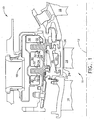
- FIG. 1 is a diagrammatic, fragmentary, partially sectional view of a turbine section of an axial flow gas turbine engine, shown generally at 10 and viewed circumferentially about engine axis 12.
- Turbine section 10 comprises a rotary blading assembly, shown generally at 11, of circumferentially rotating blading members such as rotating turbine blades 14 axially adjacent stationary turbine vanes 16.
- turbine section 10 includes a turbine stator assembly shown generally at 18 and including a circumferentially stationary turbine shroud 20, typically comprised of a plurality of circumferentially adjacent shroud segments for assembly circumferentially about turbine blades 14.
- Shroud 20 includes an inner surface 22 in juxtaposition with a blading member outer surface 24 respectively representing a first boundary and a second boundary of gap 26 between shroud inner surface 22 and blading member outer surface 24.
- the radial length of gap 26 can affect efficiency of a turbine engine. Therefore, it is desired to maintain the radial length of gap 26 as small as possible during various engine operating conditions.
- Gap control member 28 in this embodiment is a circumferential ring-like member made of a SMA and secured within stator assembly 18 operatively connected with shroud 20.
- gap control member 28 can be in direct contact with shroud 20 or, as shown in the drawings, in indirect contact with shroud 20 through one or more intermediate stator assembly members.
- Shroud 20 is movable radially responsive to movement of means such as members through which it is supported.
- fluid flow means 30 to deliver fluid to gap control member 28, in one form about gap control member 28 as shown in the drawings.
- fluid flow means 30 can be a known type of fluid flow control (not shown) using known, pre-programmed fluid valves and valve controls, for selecting fluid, for example air, from and/or about other portions of the engine to selectively vary the temperature of fluid for the fluid flow means.
- engine flowpath fluid including air and/or products of combustion, as well as external, ambient air, can be selected as desired from various portions of a compressor and/or from ambient air for disposition through the fluid flow means.
- fluid flow means 30 is represented by generally circumferential air flow chambers or manifolds including openings 32 to deliver fluid 34, for example air from an axially forward compressor (not shown), at the pre-selected temperatures about gap control member 28.
- the SMA of gap control member 28 is selected and preconditioned to deform pre-selected amounts during engine operation, responsive to the temperature of fluid 34.
- the temperature of fluid 34 can be varied by appropriate selection of the source of such fluid, for example stages of the compressor, ambient air, or their mixture.
- shroud 20 is movable generally radially toward and away from turbine blade 14.
- Shroud 20 is moved as a result of force from gap control member 28 as it deforms selectively during engine service operation In the embodiments of the drawings, such force is transmitted to shroud 20 through an intermediate member 36 of stator assembly 18.
- Such movement of shroud 20 moves shroud inner surface 22 toward or away from blading member outer surface 24 thereby changing the radial length of gap 26 and actively and selectively controlling the clearance between surfaces 22 and 24 to improve engine efficiency.
- gap control member 28 is shown in the diagrammatic, fragmentary, partially sectional view of Figure 2 .
- gap control member shown in cross section generally at 28 comprises a plurality of circumferential, discrete portions 38, 40, and 42, generally in contract to define a substantially continuous, segmented gap control member.
- Still another embodiment of gap control member 28 is shown in the diagrammatic, fragmentary, partially sectional view of Figure 3 .
- Gap control member shown in cross section generally at 28 comprises a plurality of spaced-apart discrete circumferential rings 44 and 46. Each such discrete portion can be made of the same SMA or different SMA having thermal transition properties selected for enhanced control of gap 26 during various operating conditions of the engine.
- Another form of the present invention provides a method for varying during engine operation the radial length of a gap, for example gap 26, between a circumferentially stationary surface, for example shroud inner surface 22, and a circumferentially rotating surface, for example blade outer surface 24.
- the method comprises providing means to enable stationary surface 22 to move radially.
- a first radial gap length is selected for use prior to engine operation and at least one additional radial gap length is selected for various operating conditions during engine operation.
- Gap control member 28 made of a SMA is provided operatively connected with stationary surface 22.
- the SMA is selected, preconditioned and shaped to position stationary surface 22 and rotating surface 24 across gap 26 at the first radial gap length prior to engine operation and to deform pre-selected amounts during engine operation responsive to temperature about the SMA.
- Fluid flow means 30 is provided to deliver fluid 34 at pre-selected temperatures to the SMA of gap control member 28.
- the present invention has been provided to enable a turbine engine stator assembly to change, during various engine operating conditions, a radial gap length between a surface of a static shroud and a juxtaposed surface of a rotating blading member.
Landscapes
- Engineering & Computer Science (AREA)
- Mechanical Engineering (AREA)
- General Engineering & Computer Science (AREA)
- Turbine Rotor Nozzle Sealing (AREA)
Claims (6)
- Ensemble de stator de moteur à turbine (18) espacé sur la circonférence autour d'un ensemble d'aubage rotatif de moteur à turbine (11) en travers d'un intervalle (26) ayant une première longueur radiale de l'intervalle avant le fonctionnement du moteur à turbine, l'ensemble de stator (18) comprenant un carénage circonférentiel (20) ayant une surface interne (22) définissant une première limite radiale de l'intervalle (26) et l'ensemble d'aubage rotatif (11) comprenant des éléments d'aubage (14) ayant une surface externe d'éléments d'aubage (24) définissant une seconde limite radiale de l'intervalle (26), dans lequel :le carénage circonférentiel (20) est mobile radialement ;l'ensemble de stator (18) comprend au moins un élément de commande d'intervalle (28) comprenant une pluralité de parties discrètes (38, 40, 42/44, 46) d'un alliage à mémoire de forme (SMA) en combinaison avec des moyens d'écoulement de fluide (30) pour délivrer du fluide (34) à des températures présélectionnées au SMA de l'élément de commande d'intervalle (28), la pluralité de parties de SMA discrètes (38, 40, 42/44, 46) comprenant au moins deux SMA différents ;chaque SMA de l'élément de commande d'intervalle (28) étant sélectionné et pré-conditionné pour déformer des quantités présélectionnées au cours du fonctionnement du moteur, en réponse à la température du fluide (34), pour déplacer le carénage circonférentiel (20) et la surface interne (22) du carénage radialement par rapport à la surface externe (24) des éléments d'aubage pour changer les quantités présélectionnées de la première longueur radiale de l'intervalle au cours du fonctionnement du moteur.
- Ensemble de stator (18) selon la revendication 1, dans lequel les moyens d'écoulement de fluide (30) délivrent du fluide (34) autour du SMA.
- Ensemble de stator (18) selon la revendication 1, dans lequel les moyens d'écoulement de fluide (34) comprennent une commande d'écoulement pour modifier sélectivement la température du fluide (30) au cours du fonctionnement du moteur.
- Dans un moteur à turbine, procédé de variation permettant la variation d'une longueur radiale d'un intervalle entre une surface circonférentielle stationnaire (22) et une surface circonférentielle rotative (24) comprenant les étapes consistant à :fournir des moyens (36) pour permettre à la surface fixe (22) de se déplacer radialement ;choisir une première longueur radiale de l'intervalle pour utilisation avant le fonctionnement du moteur ;sélectionner au moins une première longueur radiale supplémentaire de l'intervalle pour utilisation au cours du fonctionnement du moteur ;fournir un élément de commande d'intervalle (28) comprenant une pluralité de parties de SMA discrètes raccordées en service à la surface stationnaire (22), la pluralité de parties de SMA discrètes comprenant au moins deux SMA différents, chaque SMA étant choisi, pré-conditionné et moulé pour positionner la surface stationnaire (22) et la surface rotative (24) en travers de l'intervalle (26) à la première longueur radiale avant le fonctionnement du moteur et pour déformer des quantités présélectionnées au cours du fonctionnement du moteur en réponse à la température autour du SMA ; etfournir des moyens d'écoulement de fluide (30) pour délivrer du fluide (34) à des températures présélectionnées au SMA au cours du fonctionnement du moteur pour déformer des quantités présélectionnées afin de déplacer la surface stationnaire (22) radialement par rapport à la surface rotative (24) sur la au moins une longueur radiale supplémentaire de l'intervalle.
- Procédé selon la revendication 4, dans lequel :la surface stationnaire (22) est une surface interne d'un carénage (20) ; etla surface rotative (24) est une surface externe d'un élément d'aubage (14).
- Procédé selon la revendication 4, dans lequel les moyens d'écoulement de fluide (30) délivrent le fluide (34) autour du SMA.
Applications Claiming Priority (1)
| Application Number | Priority Date | Filing Date | Title |
|---|---|---|---|
| US11/043,369 US7367776B2 (en) | 2005-01-26 | 2005-01-26 | Turbine engine stator including shape memory alloy and clearance control method |
Publications (3)
| Publication Number | Publication Date |
|---|---|
| EP1686243A2 EP1686243A2 (fr) | 2006-08-02 |
| EP1686243A3 EP1686243A3 (fr) | 2012-05-16 |
| EP1686243B1 true EP1686243B1 (fr) | 2016-09-07 |
Family
ID=35852307
Family Applications (1)
| Application Number | Title | Priority Date | Filing Date |
|---|---|---|---|
| EP06250412.1A Not-in-force EP1686243B1 (fr) | 2005-01-26 | 2006-01-25 | Stator de turbine avec des alliages à mémoire de forme et pilotage de jeu des aubes |
Country Status (4)
| Country | Link |
|---|---|
| US (1) | US7367776B2 (fr) |
| EP (1) | EP1686243B1 (fr) |
| JP (1) | JP4805682B2 (fr) |
| CA (1) | CA2533576C (fr) |
Cited By (1)
| Publication number | Priority date | Publication date | Assignee | Title |
|---|---|---|---|---|
| RU2716648C1 (ru) * | 2019-07-16 | 2020-03-13 | ФЕДЕРАЛЬНОЕ ГОСУДАРСТВЕННОЕ БЮДЖЕТНОЕ ОБРАЗОВАТЕЛЬНОЕ УЧРЕЖДЕНИЕ ВЫСШЕГО ОБРАЗОВАНИЯ "Брянский государственный технический университет" | Охлаждаемая лопатка газовой турбины |
Families Citing this family (41)
| Publication number | Priority date | Publication date | Assignee | Title |
|---|---|---|---|---|
| DE102005013796A1 (de) * | 2005-03-24 | 2006-09-28 | Alstom Technology Ltd. | Wärmestausegment |
| DE102005013797A1 (de) * | 2005-03-24 | 2006-09-28 | Alstom Technology Ltd. | Wärmestausegment |
| US7665960B2 (en) * | 2006-08-10 | 2010-02-23 | United Technologies Corporation | Turbine shroud thermal distortion control |
| US7823389B2 (en) * | 2006-11-15 | 2010-11-02 | General Electric Company | Compound clearance control engine |
| US20150083281A1 (en) * | 2007-12-26 | 2015-03-26 | General Electric Company | High temperature shape memory alloy actuators |
| FR2931872B1 (fr) * | 2008-05-28 | 2010-08-20 | Snecma | Turbine haute pression d'une turbomachine avec montage ameliore du boitier de pilotage des jeux radiaux d'aubes mobiles. |
| DE102008033783A1 (de) * | 2008-07-18 | 2010-01-21 | Mtu Aero Engines Gmbh | Gasturbine und Verfahren zum Ändern der aerodynamischen Gestalt einer Gasturbinenschaufel |
| EP2226469A1 (fr) * | 2009-03-04 | 2010-09-08 | Siemens Aktiengesellschaft | Composants de turbine dotés d'une couche de protection |
| US8277172B2 (en) * | 2009-03-23 | 2012-10-02 | General Electric Company | Apparatus for turbine engine cooling air management |
| US8142141B2 (en) * | 2009-03-23 | 2012-03-27 | General Electric Company | Apparatus for turbine engine cooling air management |
| EP2239423A1 (fr) * | 2009-03-31 | 2010-10-13 | Siemens Aktiengesellschaft | Turbomachine axiale dotée d'un contrôle passif d'étanchéité en bout d'aube |
| GB0907513D0 (en) * | 2009-05-01 | 2009-06-10 | Rolls Royce Plc | A flow modulating device |
| FR2972483B1 (fr) * | 2011-03-07 | 2013-04-19 | Snecma | Carter de turbine comportant des moyens de fixation de secteurs d'anneau |
| CH704995A1 (de) * | 2011-05-24 | 2012-11-30 | Alstom Technology Ltd | Turbomaschine. |
| US8939709B2 (en) | 2011-07-18 | 2015-01-27 | General Electric Company | Clearance control for a turbine |
| US20130034423A1 (en) * | 2011-08-01 | 2013-02-07 | General Electric Company | System and method for passively controlling clearance in a gas turbine engine |
| CH705551A1 (de) * | 2011-09-19 | 2013-03-28 | Alstom Technology Ltd | Selbstjustierende Einrichtung zum Steuern des Spielraums, insbesondere in radialer Richtung, zwischen rotierenden und stationären Komponenten einer thermisch belasteten Turbomaschine. |
| RU2498085C1 (ru) * | 2012-04-04 | 2013-11-10 | Николай Борисович Болотин | Газотурбинный двигатель |
| RU2506433C2 (ru) * | 2012-04-04 | 2014-02-10 | Николай Борисович Болотин | Газотурбинный двигатель |
| RU2506434C2 (ru) * | 2012-04-04 | 2014-02-10 | Николай Борисович Болотин | Газотурбинный двигатель |
| RU2490474C1 (ru) * | 2012-04-16 | 2013-08-20 | Николай Борисович Болотин | Турбина газотурбинного двигателя |
| RU2499892C1 (ru) * | 2012-04-24 | 2013-11-27 | Николай Борисович Болотин | Турбина газотурбинного двигателя |
| RU2499145C1 (ru) * | 2012-05-21 | 2013-11-20 | Николай Борисович Болотин | Турбина двухконтурного газотурбинного двигателя |
| RU2496991C1 (ru) * | 2012-05-21 | 2013-10-27 | Николай Борисович Болотин | Турбина двухконтурного газотурбинного двигателя |
| RU2501956C1 (ru) * | 2012-07-31 | 2013-12-20 | Николай Борисович Болотин | Двухконтурный газотурбинный двигатель, способ регулирования радиального зазора в турбине двухконтурного газотурбинного двигателя |
| US9598975B2 (en) | 2013-03-14 | 2017-03-21 | Rolls-Royce Corporation | Blade track assembly with turbine tip clearance control |
| WO2015102702A2 (fr) | 2013-10-07 | 2015-07-09 | United Technologies Corporation | Système de commande thermique personnalisé pour réseau de joints étanches à l'air externe d'un moteur à turbine à gaz |
| JP6223111B2 (ja) * | 2013-10-15 | 2017-11-01 | 三菱日立パワーシステムズ株式会社 | ガスタービン |
| RU2537646C1 (ru) * | 2013-12-30 | 2015-01-10 | Федеральное государственное унитарное предприятие "Научно-производственный центр газотурбостроения "Салют" (ФГУП "НПЦ газотурбостроения "Салют") | Способ регулирования радиального зазора в турбине газотурбинного двигателя |
| RU2567885C1 (ru) * | 2014-08-08 | 2015-11-10 | Российская Федерация, от имени которой выступает Министерство промышленности и торговли Российской Федерации (Минпромторг России) | Статор компрессора |
| CN108019242B (zh) * | 2017-12-15 | 2019-08-06 | 北京航空航天大学 | 基于形状记忆合金丝的航空发动机叶尖间隙主动控制装置 |
| US11021998B2 (en) | 2019-08-08 | 2021-06-01 | General Electric Company | Shape memory alloy sleeve support assembly for a bearing |
| US11828235B2 (en) | 2020-12-08 | 2023-11-28 | General Electric Company | Gearbox for a gas turbine engine utilizing shape memory alloy dampers |
| CN113090342B (zh) * | 2021-04-08 | 2023-01-13 | 沈阳航空航天大学 | 基于记忆合金丝的主动间隙控制篦齿密封结构 |
| US11674399B2 (en) | 2021-07-07 | 2023-06-13 | General Electric Company | Airfoil arrangement for a gas turbine engine utilizing a shape memory alloy |
| US11668317B2 (en) | 2021-07-09 | 2023-06-06 | General Electric Company | Airfoil arrangement for a gas turbine engine utilizing a shape memory alloy |
| US11788425B2 (en) * | 2021-11-05 | 2023-10-17 | General Electric Company | Gas turbine engine with clearance control system |
| US12012859B2 (en) | 2022-07-11 | 2024-06-18 | General Electric Company | Variable flowpath casings for blade tip clearance control |
| US12049828B2 (en) | 2022-07-12 | 2024-07-30 | General Electric Company | Active clearance control of fan blade tip closure using a variable sleeve system |
| US11808157B1 (en) | 2022-07-13 | 2023-11-07 | General Electric Company | Variable flowpath casings for blade tip clearance control |
| US12006829B1 (en) | 2023-02-16 | 2024-06-11 | General Electric Company | Seal member support system for a gas turbine engine |
Family Cites Families (18)
| Publication number | Priority date | Publication date | Assignee | Title |
|---|---|---|---|---|
| JPS57195803A (en) * | 1981-05-27 | 1982-12-01 | Hitachi Ltd | Adjusting device of tip clearance in turbo fluidic machine |
| JPS58206807A (ja) * | 1982-05-28 | 1983-12-02 | Hitachi Ltd | 軸流タ−ビンの動翼先端すき間制御装置 |
| JPS5918208A (ja) * | 1982-07-21 | 1984-01-30 | Toshiba Corp | ラビリンスパツキン |
| JPS59110876A (ja) * | 1982-12-16 | 1984-06-26 | Keihin Seiki Mfg Co Ltd | 形状記憶合金よりなる駆動体の加熱方法 |
| JPS60111004A (ja) * | 1983-11-21 | 1985-06-17 | Hitachi Ltd | 軸流形流体機械のケ−シング |
| JPS61103504U (fr) * | 1984-12-12 | 1986-07-01 | ||
| JPS61250304A (ja) * | 1985-04-26 | 1986-11-07 | Toshiba Corp | 軸流タ−ビン |
| JPS6435001A (en) * | 1987-07-30 | 1989-02-06 | Toshiba Corp | Gap adjusting device for seal part of turbine |
| JPH01240776A (ja) * | 1988-03-18 | 1989-09-26 | Matsushita Electric Ind Co Ltd | 流路切換え作動装置 |
| US6065934A (en) | 1997-02-28 | 2000-05-23 | The Boeing Company | Shape memory rotary actuator |
| US6220550B1 (en) | 1998-03-31 | 2001-04-24 | Continuum Dynamics, Inc. | Actuating device with multiple stable positions |
| US6135713A (en) | 1999-01-19 | 2000-10-24 | The Mcdonnell Douglas Helicopter Company | Helicopter rotor blade flap actuator government interest |
| GB2354290B (en) | 1999-09-18 | 2004-02-25 | Rolls Royce Plc | A cooling air flow control device for a gas turbine engine |
| US6367253B2 (en) | 1999-12-20 | 2002-04-09 | Las, L.L.C. | Shape memory alloy actuators for aircraft landing gear |
| US6318070B1 (en) | 2000-03-03 | 2001-11-20 | United Technologies Corporation | Variable area nozzle for gas turbine engines driven by shape memory alloy actuators |
| GB2363864B (en) * | 2000-06-23 | 2004-08-18 | Rolls Royce Plc | A control arrangement |
| JP2002285802A (ja) * | 2001-03-26 | 2002-10-03 | Toshiba Corp | 回転機械のラビリンスシール装置 |
| GB0308147D0 (en) * | 2003-04-09 | 2003-05-14 | Rolls Royce Plc | A seal |
-
2005
- 2005-01-26 US US11/043,369 patent/US7367776B2/en active Active
-
2006
- 2006-01-19 CA CA2533576A patent/CA2533576C/fr not_active Expired - Fee Related
- 2006-01-23 JP JP2006013360A patent/JP4805682B2/ja not_active Expired - Fee Related
- 2006-01-25 EP EP06250412.1A patent/EP1686243B1/fr not_active Not-in-force
Non-Patent Citations (1)
| Title |
|---|
| None * |
Cited By (1)
| Publication number | Priority date | Publication date | Assignee | Title |
|---|---|---|---|---|
| RU2716648C1 (ru) * | 2019-07-16 | 2020-03-13 | ФЕДЕРАЛЬНОЕ ГОСУДАРСТВЕННОЕ БЮДЖЕТНОЕ ОБРАЗОВАТЕЛЬНОЕ УЧРЕЖДЕНИЕ ВЫСШЕГО ОБРАЗОВАНИЯ "Брянский государственный технический университет" | Охлаждаемая лопатка газовой турбины |
Also Published As
| Publication number | Publication date |
|---|---|
| US20060165518A1 (en) | 2006-07-27 |
| EP1686243A2 (fr) | 2006-08-02 |
| JP4805682B2 (ja) | 2011-11-02 |
| JP2006207584A (ja) | 2006-08-10 |
| EP1686243A3 (fr) | 2012-05-16 |
| US7367776B2 (en) | 2008-05-06 |
| CA2533576C (fr) | 2015-03-10 |
| CA2533576A1 (fr) | 2006-07-26 |
Similar Documents
| Publication | Publication Date | Title |
|---|---|---|
| EP1686243B1 (fr) | Stator de turbine avec des alliages à mémoire de forme et pilotage de jeu des aubes | |
| US10316687B2 (en) | Blade track assembly with turbine tip clearance control | |
| US7946808B2 (en) | Seal between rotor blade platforms and stator vane platforms, a rotor blade and a stator vane | |
| CA2772384C (fr) | Anneau de renforcement de turbine composite a anneau continu | |
| EP1643084B1 (fr) | Segment de virole pour une moteur à turbine et dispositif de suspension | |
| EP2613015B1 (fr) | Joint d'air externe de lames hybrides pour moteur à turbine à gaz | |
| EP2875224B1 (fr) | Commande de position radiale d'une structure supportée par une boîte | |
| EP2554797A2 (fr) | Système et procédé permettant de commander passivement le jeu dans un moteur de turbine à gaz | |
| EP0381895B1 (fr) | Dispositif de réglage du jeu des extrémités d'aubes de turbine à gaz | |
| EP2037083B1 (fr) | Dispositif d'étanchéité pour un composant de moteurs de turbine à gaz | |
| US10408080B2 (en) | Tailored thermal control system for gas turbine engine blade outer air seal array | |
| CH705551A1 (de) | Selbstjustierende Einrichtung zum Steuern des Spielraums, insbesondere in radialer Richtung, zwischen rotierenden und stationären Komponenten einer thermisch belasteten Turbomaschine. | |
| EP3249171B1 (fr) | Ensemble joint d'étanchéité | |
| US9835171B2 (en) | Vane carrier assembly | |
| EP3008289B1 (fr) | Ensemble d'aube statorique avec longeron et coque mobiles | |
| EP3581767B1 (fr) | Commande passive de jeu pour un carénage de roue centrifuge | |
| US20180010617A1 (en) | Gas turbine compressor passive clearance control | |
| US20160258310A1 (en) | Seal arrangement | |
| EP2941540B1 (fr) | Surface portante à profil variable réactif à des conditions thermiques | |
| US20200123928A1 (en) | Turbine assembly with ceramic matrix composite vane components and cooling features | |
| US20140140807A1 (en) | Turbine shroud arrangement for a turbine system and method of controlling a turbine shroud arrangement | |
| EP3055512B1 (fr) | Portée de balai d'étanchéité à inflexion non linéaire | |
| EP3513041B1 (fr) | Actionneur thermomécanique bimétallique | |
| WO2024179738A1 (fr) | Segment annulaire pour un moteur à turbine à gaz et procédé mis en œuvre par ordinateur pour concevoir ledit segment annulaire |
Legal Events
| Date | Code | Title | Description |
|---|---|---|---|
| PUAI | Public reference made under article 153(3) epc to a published international application that has entered the european phase |
Free format text: ORIGINAL CODE: 0009012 |
|
| AK | Designated contracting states |
Kind code of ref document: A2 Designated state(s): AT BE BG CH CY CZ DE DK EE ES FI FR GB GR HU IE IS IT LI LT LU LV MC NL PL PT RO SE SI SK TR |
|
| AX | Request for extension of the european patent |
Extension state: AL BA HR MK YU |
|
| PUAL | Search report despatched |
Free format text: ORIGINAL CODE: 0009013 |
|
| AK | Designated contracting states |
Kind code of ref document: A3 Designated state(s): AT BE BG CH CY CZ DE DK EE ES FI FR GB GR HU IE IS IT LI LT LU LV MC NL PL PT RO SE SI SK TR |
|
| AX | Request for extension of the european patent |
Extension state: AL BA HR MK YU |
|
| RIC1 | Information provided on ipc code assigned before grant |
Ipc: F01D 11/24 20060101AFI20120411BHEP Ipc: F01D 11/18 20060101ALI20120411BHEP |
|
| 17P | Request for examination filed |
Effective date: 20121116 |
|
| AKX | Designation fees paid |
Designated state(s): DE FR GB |
|
| GRAP | Despatch of communication of intention to grant a patent |
Free format text: ORIGINAL CODE: EPIDOSNIGR1 |
|
| INTG | Intention to grant announced |
Effective date: 20160429 |
|
| GRAS | Grant fee paid |
Free format text: ORIGINAL CODE: EPIDOSNIGR3 |
|
| GRAJ | Information related to disapproval of communication of intention to grant by the applicant or resumption of examination proceedings by the epo deleted |
Free format text: ORIGINAL CODE: EPIDOSDIGR1 |
|
| GRAL | Information related to payment of fee for publishing/printing deleted |
Free format text: ORIGINAL CODE: EPIDOSDIGR3 |
|
| GRAR | Information related to intention to grant a patent recorded |
Free format text: ORIGINAL CODE: EPIDOSNIGR71 |
|
| GRAA | (expected) grant |
Free format text: ORIGINAL CODE: 0009210 |
|
| INTC | Intention to grant announced (deleted) | ||
| INTG | Intention to grant announced |
Effective date: 20160726 |
|
| AK | Designated contracting states |
Kind code of ref document: B1 Designated state(s): DE FR GB |
|
| REG | Reference to a national code |
Ref country code: GB Ref legal event code: FG4D |
|
| REG | Reference to a national code |
Ref country code: DE Ref legal event code: R096 Ref document number: 602006050186 Country of ref document: DE |
|
| REG | Reference to a national code |
Ref country code: FR Ref legal event code: PLFP Year of fee payment: 12 |
|
| PGFP | Annual fee paid to national office [announced via postgrant information from national office to epo] |
Ref country code: DE Payment date: 20170125 Year of fee payment: 12 Ref country code: FR Payment date: 20170125 Year of fee payment: 12 |
|
| PGFP | Annual fee paid to national office [announced via postgrant information from national office to epo] |
Ref country code: GB Payment date: 20170127 Year of fee payment: 12 |
|
| REG | Reference to a national code |
Ref country code: DE Ref legal event code: R097 Ref document number: 602006050186 Country of ref document: DE |
|
| PLBE | No opposition filed within time limit |
Free format text: ORIGINAL CODE: 0009261 |
|
| STAA | Information on the status of an ep patent application or granted ep patent |
Free format text: STATUS: NO OPPOSITION FILED WITHIN TIME LIMIT |
|
| 26N | No opposition filed |
Effective date: 20170608 |
|
| REG | Reference to a national code |
Ref country code: DE Ref legal event code: R119 Ref document number: 602006050186 Country of ref document: DE |
|
| GBPC | Gb: european patent ceased through non-payment of renewal fee |
Effective date: 20180125 |
|
| PG25 | Lapsed in a contracting state [announced via postgrant information from national office to epo] |
Ref country code: DE Free format text: LAPSE BECAUSE OF NON-PAYMENT OF DUE FEES Effective date: 20180801 Ref country code: FR Free format text: LAPSE BECAUSE OF NON-PAYMENT OF DUE FEES Effective date: 20180131 |
|
| REG | Reference to a national code |
Ref country code: FR Ref legal event code: ST Effective date: 20180928 |
|
| PG25 | Lapsed in a contracting state [announced via postgrant information from national office to epo] |
Ref country code: GB Free format text: LAPSE BECAUSE OF NON-PAYMENT OF DUE FEES Effective date: 20180125 |