EP1685887B1 - Elektrodialyseeluationsmittelgenerator für ionenchromatographie - Google Patents
Elektrodialyseeluationsmittelgenerator für ionenchromatographie Download PDFInfo
- Publication number
- EP1685887B1 EP1685887B1 EP04719163A EP04719163A EP1685887B1 EP 1685887 B1 EP1685887 B1 EP 1685887B1 EP 04719163 A EP04719163 A EP 04719163A EP 04719163 A EP04719163 A EP 04719163A EP 1685887 B1 EP1685887 B1 EP 1685887B1
- Authority
- EP
- European Patent Office
- Prior art keywords
- eluent
- ion
- electron
- generating chamber
- exchange membrane
- Prior art date
- Legal status (The legal status is an assumption and is not a legal conclusion. Google has not performed a legal analysis and makes no representation as to the accuracy of the status listed.)
- Expired - Lifetime
Links
- 239000003480 eluent Substances 0.000 title claims abstract description 97
- 238000004255 ion exchange chromatography Methods 0.000 title claims abstract description 7
- 238000000909 electrodialysis Methods 0.000 title abstract 2
- 239000003014 ion exchange membrane Substances 0.000 claims abstract description 28
- 230000000694 effects Effects 0.000 claims abstract description 4
- 150000002500 ions Chemical class 0.000 claims description 43
- 230000004888 barrier function Effects 0.000 claims description 32
- KDLHZDBZIXYQEI-UHFFFAOYSA-N Palladium Chemical compound [Pd] KDLHZDBZIXYQEI-UHFFFAOYSA-N 0.000 claims description 26
- BASFCYQUMIYNBI-UHFFFAOYSA-N platinum Chemical compound [Pt] BASFCYQUMIYNBI-UHFFFAOYSA-N 0.000 claims description 21
- XLYOFNOQVPJJNP-UHFFFAOYSA-N water Substances O XLYOFNOQVPJJNP-UHFFFAOYSA-N 0.000 claims description 21
- 229910052763 palladium Inorganic materials 0.000 claims description 13
- 229910052697 platinum Inorganic materials 0.000 claims description 10
- 238000012546 transfer Methods 0.000 claims description 8
- 229910052751 metal Inorganic materials 0.000 claims description 7
- 239000002184 metal Substances 0.000 claims description 7
- 239000007788 liquid Substances 0.000 claims description 6
- RTAQQCXQSZGOHL-UHFFFAOYSA-N Titanium Chemical compound [Ti] RTAQQCXQSZGOHL-UHFFFAOYSA-N 0.000 claims description 4
- 230000005684 electric field Effects 0.000 claims description 4
- 229910001220 stainless steel Inorganic materials 0.000 claims description 4
- 239000010935 stainless steel Substances 0.000 claims description 4
- 239000010936 titanium Substances 0.000 claims description 4
- 229910052719 titanium Inorganic materials 0.000 claims description 4
- 239000012528 membrane Substances 0.000 abstract description 33
- 238000004458 analytical method Methods 0.000 abstract description 2
- 239000007864 aqueous solution Substances 0.000 abstract 1
- 239000000243 solution Substances 0.000 description 45
- KWYUFKZDYYNOTN-UHFFFAOYSA-M Potassium hydroxide Chemical compound [OH-].[K+] KWYUFKZDYYNOTN-UHFFFAOYSA-M 0.000 description 32
- 239000002585 base Substances 0.000 description 30
- 238000010828 elution Methods 0.000 description 23
- 239000007789 gas Substances 0.000 description 23
- 239000002253 acid Substances 0.000 description 19
- 150000001450 anions Chemical class 0.000 description 14
- 238000000034 method Methods 0.000 description 14
- 150000001768 cations Chemical class 0.000 description 12
- -1 hydrogen ions Chemical class 0.000 description 12
- 230000008569 process Effects 0.000 description 9
- 239000003795 chemical substances by application Substances 0.000 description 8
- 239000003513 alkali Substances 0.000 description 7
- 239000001257 hydrogen Substances 0.000 description 7
- 229910052739 hydrogen Inorganic materials 0.000 description 7
- PXHVJJICTQNCMI-UHFFFAOYSA-N Nickel Chemical compound [Ni] PXHVJJICTQNCMI-UHFFFAOYSA-N 0.000 description 6
- 238000005341 cation exchange Methods 0.000 description 6
- 238000007872 degassing Methods 0.000 description 6
- XLYOFNOQVPJJNP-UHFFFAOYSA-M hydroxide Chemical compound [OH-] XLYOFNOQVPJJNP-UHFFFAOYSA-M 0.000 description 6
- GRYLNZFGIOXLOG-UHFFFAOYSA-N Nitric acid Chemical compound O[N+]([O-])=O GRYLNZFGIOXLOG-UHFFFAOYSA-N 0.000 description 5
- 239000003011 anion exchange membrane Substances 0.000 description 5
- 238000005868 electrolysis reaction Methods 0.000 description 5
- 229910017604 nitric acid Inorganic materials 0.000 description 5
- 238000000926 separation method Methods 0.000 description 5
- 150000007513 acids Chemical class 0.000 description 4
- QVGXLLKOCUKJST-UHFFFAOYSA-N atomic oxygen Chemical compound [O] QVGXLLKOCUKJST-UHFFFAOYSA-N 0.000 description 4
- 230000015572 biosynthetic process Effects 0.000 description 4
- 238000013375 chromatographic separation Methods 0.000 description 4
- 239000011248 coating agent Substances 0.000 description 4
- 238000000576 coating method Methods 0.000 description 4
- 238000000354 decomposition reaction Methods 0.000 description 4
- 238000001514 detection method Methods 0.000 description 4
- 238000004519 manufacturing process Methods 0.000 description 4
- 239000000203 mixture Substances 0.000 description 4
- 229910052760 oxygen Inorganic materials 0.000 description 4
- 239000001301 oxygen Substances 0.000 description 4
- BVKZGUZCCUSVTD-UHFFFAOYSA-L Carbonate Chemical compound [O-]C([O-])=O BVKZGUZCCUSVTD-UHFFFAOYSA-L 0.000 description 3
- FZNCGRZWXLXZSZ-CIQUZCHMSA-N Voglibose Chemical compound OCC(CO)N[C@H]1C[C@](O)(CO)[C@@H](O)[C@H](O)[C@H]1O FZNCGRZWXLXZSZ-CIQUZCHMSA-N 0.000 description 3
- 230000009471 action Effects 0.000 description 3
- 229910052783 alkali metal Inorganic materials 0.000 description 3
- 150000001340 alkali metals Chemical class 0.000 description 3
- 230000003197 catalytic effect Effects 0.000 description 3
- 238000000502 dialysis Methods 0.000 description 3
- 229910052759 nickel Inorganic materials 0.000 description 3
- 238000002360 preparation method Methods 0.000 description 3
- 238000001179 sorption measurement Methods 0.000 description 3
- VHUUQVKOLVNVRT-UHFFFAOYSA-N Ammonium hydroxide Chemical compound [NH4+].[OH-] VHUUQVKOLVNVRT-UHFFFAOYSA-N 0.000 description 2
- 229910002651 NO3 Inorganic materials 0.000 description 2
- 239000000908 ammonium hydroxide Substances 0.000 description 2
- 230000008901 benefit Effects 0.000 description 2
- 230000008859 change Effects 0.000 description 2
- 238000006243 chemical reaction Methods 0.000 description 2
- 238000004587 chromatography analysis Methods 0.000 description 2
- 239000008367 deionised water Substances 0.000 description 2
- 229910021641 deionized water Inorganic materials 0.000 description 2
- 230000002452 interceptive effect Effects 0.000 description 2
- 230000005012 migration Effects 0.000 description 2
- 238000013508 migration Methods 0.000 description 2
- 239000012811 non-conductive material Substances 0.000 description 2
- PIBWKRNGBLPSSY-UHFFFAOYSA-L palladium(II) chloride Chemical compound Cl[Pd]Cl PIBWKRNGBLPSSY-UHFFFAOYSA-L 0.000 description 2
- 229910001414 potassium ion Inorganic materials 0.000 description 2
- FGIUAXJPYTZDNR-UHFFFAOYSA-N potassium nitrate Chemical compound [K+].[O-][N+]([O-])=O FGIUAXJPYTZDNR-UHFFFAOYSA-N 0.000 description 2
- 230000001629 suppression Effects 0.000 description 2
- LWIHDJKSTIGBAC-UHFFFAOYSA-K tripotassium phosphate Chemical compound [K+].[K+].[K+].[O-]P([O-])([O-])=O LWIHDJKSTIGBAC-UHFFFAOYSA-K 0.000 description 2
- 239000012498 ultrapure water Substances 0.000 description 2
- NWUYHJFMYQTDRP-UHFFFAOYSA-N 1,2-bis(ethenyl)benzene;1-ethenyl-2-ethylbenzene;styrene Chemical compound C=CC1=CC=CC=C1.CCC1=CC=CC=C1C=C.C=CC1=CC=CC=C1C=C NWUYHJFMYQTDRP-UHFFFAOYSA-N 0.000 description 1
- 239000004215 Carbon black (E152) Substances 0.000 description 1
- ZGTMUACCHSMWAC-UHFFFAOYSA-L EDTA disodium salt (anhydrous) Chemical compound [Na+].[Na+].OC(=O)CN(CC([O-])=O)CCN(CC(O)=O)CC([O-])=O ZGTMUACCHSMWAC-UHFFFAOYSA-L 0.000 description 1
- UFHFLCQGNIYNRP-UHFFFAOYSA-N Hydrogen Chemical compound [H][H] UFHFLCQGNIYNRP-UHFFFAOYSA-N 0.000 description 1
- NPYPAHLBTDXSSS-UHFFFAOYSA-N Potassium ion Chemical compound [K+] NPYPAHLBTDXSSS-UHFFFAOYSA-N 0.000 description 1
- 238000010521 absorption reaction Methods 0.000 description 1
- 125000000129 anionic group Chemical group 0.000 description 1
- 150000004649 carbonic acid derivatives Chemical class 0.000 description 1
- 238000005234 chemical deposition Methods 0.000 description 1
- 230000020169 heat generation Effects 0.000 description 1
- 229930195733 hydrocarbon Natural products 0.000 description 1
- 150000002430 hydrocarbons Chemical class 0.000 description 1
- 150000004679 hydroxides Chemical class 0.000 description 1
- 230000006872 improvement Effects 0.000 description 1
- 239000003456 ion exchange resin Substances 0.000 description 1
- 229920003303 ion-exchange polymer Polymers 0.000 description 1
- 238000004811 liquid chromatography Methods 0.000 description 1
- 238000012423 maintenance Methods 0.000 description 1
- 239000000463 material Substances 0.000 description 1
- 238000005259 measurement Methods 0.000 description 1
- 238000012544 monitoring process Methods 0.000 description 1
- 229920000642 polymer Polymers 0.000 description 1
- XAEFZNCEHLXOMS-UHFFFAOYSA-M potassium benzoate Chemical compound [K+].[O-]C(=O)C1=CC=CC=C1 XAEFZNCEHLXOMS-UHFFFAOYSA-M 0.000 description 1
- 235000010333 potassium nitrate Nutrition 0.000 description 1
- 239000004323 potassium nitrate Substances 0.000 description 1
- 229910000160 potassium phosphate Inorganic materials 0.000 description 1
- 235000011009 potassium phosphates Nutrition 0.000 description 1
- 230000001681 protective effect Effects 0.000 description 1
- 239000012266 salt solution Substances 0.000 description 1
- 210000002023 somite Anatomy 0.000 description 1
- 239000000126 substance Substances 0.000 description 1
- 150000003463 sulfur Chemical class 0.000 description 1
- 230000008961 swelling Effects 0.000 description 1
Images

Classifications
-
- G—PHYSICS
- G01—MEASURING; TESTING
- G01N—INVESTIGATING OR ANALYSING MATERIALS BY DETERMINING THEIR CHEMICAL OR PHYSICAL PROPERTIES
- G01N30/00—Investigating or analysing materials by separation into components using adsorption, absorption or similar phenomena or using ion-exchange, e.g. chromatography or field flow fractionation
- G01N30/96—Investigating or analysing materials by separation into components using adsorption, absorption or similar phenomena or using ion-exchange, e.g. chromatography or field flow fractionation using ion-exchange
-
- G—PHYSICS
- G01—MEASURING; TESTING
- G01N—INVESTIGATING OR ANALYSING MATERIALS BY DETERMINING THEIR CHEMICAL OR PHYSICAL PROPERTIES
- G01N30/00—Investigating or analysing materials by separation into components using adsorption, absorption or similar phenomena or using ion-exchange, e.g. chromatography or field flow fractionation
- G01N30/02—Column chromatography
- G01N30/26—Conditioning of the fluid carrier; Flow patterns
- G01N30/28—Control of physical parameters of the fluid carrier
- G01N30/34—Control of physical parameters of the fluid carrier of fluid composition, e.g. gradient
-
- G—PHYSICS
- G01—MEASURING; TESTING
- G01N—INVESTIGATING OR ANALYSING MATERIALS BY DETERMINING THEIR CHEMICAL OR PHYSICAL PROPERTIES
- G01N30/00—Investigating or analysing materials by separation into components using adsorption, absorption or similar phenomena or using ion-exchange, e.g. chromatography or field flow fractionation
- G01N30/02—Column chromatography
- G01N30/60—Construction of the column
- G01N30/6052—Construction of the column body
- G01N30/6069—Construction of the column body with compartments or bed substructure
Definitions
- the invention belongs to the field of ion chromatographic analysis, namely to the field of elution agent generation equipment for ion chromatography.
- ion chromatography One of the most effective methods of analyzing anionic components in water solutions is ion chromatography. With this method, the anions of the sample to be determined are separated in an analytical column by means of alkali elution agents (solutions of weak acids and strong bases, hydroxides of alkali metals, etc.) with a further conductometric detection.
- alkali elution agents solutions of weak acids and strong bases, hydroxides of alkali metals, etc.
- a device for the diffuse production of an alkali eluting agent ( WS Gurskiy, LA Godon, SW Timofeyev, Hydroxide Elution Agent for Ion Chromatographic Anion Determination, "Zh. Werkslabor", Vol. 63, No. 12, p. 11, 1997 ).
- high-purity water is passed through cation exchange capillary whose outer surface with the concentrated solution of an alkali, z.
- potassium hydroxide comes into contact.
- potassium hydroxide solution eluent
- the eluent (potassium hydroxide solution) to be produced in the device contains no carbonate ions.
- concentration of potassium hydroxide in the eluent is determined by the flow rate of the eluent through the capillary and can be varied by the contact area of the concentrated potassium hydroxide solution with the capillary.
- a device for keeping the temperature constant is necessary because the diffuse flow of potassium hydroxide through the membrane depends on the temperature.
- the device in the eluent line under a pressure of max. 3-4 at work and accordingly in the hydraulic line of the high pressure in the chromatography (after the pump) can not be arranged.
- elution generating means in which the eluent is generated as a result of the transfer of the required ions through the ion exchanger under the action of an electric field.
- the eluent concentration can be easily varied by changing the electrical parameters such as the current.
- the eluent is passed through a degassing device in which the eluent channel is separated from the channel with the gas by means of a gas-selective membrane which allows gas to pass and retains liquid.
- a gas-selective membrane which allows gas to pass and retains liquid.
- the device can be used to generate acid or base in a chromatographic system or in another analytical system where high purity acids or bases are needed.
- the device according to the patent has a number of disadvantages. In the first place, this is a high heat generated in the device, which is due to the high electrical resistance of the water solutions that are rich in electrolysis gases.
- the patent prototype identifies two possibilities.
- a flow boundary for increasing the pressure throughout the chromatographic system is placed after the detector.
- high pressure eg 70at and more
- the gas in the eluent dissolves almost completely and negligibly influences the course of the chromatographic process of separation and detection.
- This method requires a detector with a flow cell that can withstand a high pressure of 70at and more.
- the eluting agent suppression IC the method described above requires that the suppressor can withstand the pressure of 70at and more. This makes the detector and suppressor structure considerably complicated and does not allow the use of standard chromatographic systems.
- Another problem solution of the gas evolution consists in the arrangement of an additional device for degassing the solution after the eluent generator.
- the eluent flow together with the dissolved gas migrates after the eluent generator under high pressure into the polymeric capillary.
- the gas penetrates through the capillary walls. From the outside of the gas-selective capillary, which is arranged in a protective tube, the liquid flows.
- the gas diffused through the capillary walls is removed by a liquid flow which simultaneously prevents the adsorption of the hydrocarbon dioxide from the environment into the eluent.
- Prototype should be used in any case an additional device for degassing of the eluent or to eliminate the disturbing effect of the eluent or increased demands on the elements of the chromatographic channel measurement.
- an eluent producing chamber 1 having an inlet end 2 and an outlet end 3 is separated from an ion source container 4 by a barrier 5 forming an ion exchange membrane.
- the barrier 5 is impermeable to the solution flow and has the property of transmitting only ions of the same charge.
- a first electrode 6 is arranged in the form of an electron-conducting, porous layer.
- the eluent generating chamber 1 is bounded by a second electrode 7.
- the second electrode 7 is designed in the form of an ion exchange membrane 8 with a single-sided, electron-conducting, porous coating 9.
- the electron-conductive porous layer is applied to the outside (with respect to the elution generating chamber) of the ion exchange membrane.
- the electrodes 6, 7 are connected to a supply source 10.
- the electron-conducting layers are applied to the surface of the ion exchange membrane by means of chemical deposition.
- layers of platinum or palladium are used as the electron-conducting layers.
- the choice of material is due to a high chemical resistance of platinum and palladium as the anode or cathode in the solutions used.
- the electron-conductive, porous coating for example, the following method can be used.
- the membrane is watered in water for 1-2 hours until swelling. Thereafter, the membrane coated with a metal layer is brought into contact with a solution of the following composition: 5 g / l palladium chloride, 100g / l ammonium hydroxide, 20min contact time.
- the membrane surface is rinsed with water and comes for one minute in contact with a heated to 80 ° C Hydrasinown (100g / l). As a result, a catalytic palladium layer is formed on the membrane surface.
- the membrane surface with the applied catalytic layer is brought into contact with a solution of the following composition: 4 g / l palladium chloride, 300 ml / l ammonium hydroxide (25%), 12g / l Trilon B, 2g / l Hydrasin.
- the temperature of the solution is 20 ° C.
- the Hydrasin is added to the solution immediately before use.
- the contact time of the membrane surface with the solution is 2-4 hours. A shorter contact time leads to the formation of an electron-conducting layer with a high electrical resistance. A longer contact time results in the formation of a non-porous palladium layer that hinders ion transfer through the membrane.
- the membrane surface with the applied catalytic palladium layer is brought into contact with a solution of the following composition: 40 g / l (NH 4 ) 2 PtCl 6 , 320 g / l NH 4 Cl.
- the temperature of the solution is 50 ° C.
- the contact time of the membrane surface with the solution is 2-4 hours. A shorter contact time leads to the formation of a Electron-conducting layer with a high electrical resistance. A longer contact time results in the formation of a non-porous platinum layer which hinders ion transfer through the membrane.
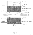
- FIG Fig. 2 Processes that occur in the course of alkali elution generation in the device according to the invention are schematically shown in FIG Fig. 2 shown.
- the container 4 is filled with a concentrated solution containing cations, the cations then becoming an eluant component.
- the potassium hydroxide solution is generated, the container is filled with the concentrated potassium hydroxide or potassium salt solution, for example, potassium phosphate solution.
- the cation exchange membrane based on, for example, perfluorinated sulfur polymer with the electrode 6 in the form of an electron-conducting palladium or platinum layer, which constitutes the anode, serves as a barrier between the generating chamber and the container.
- the cation exchange membrane can only pass cations.
- the eluent generating chamber 1 is separated by the second electrode 7, which is formed as an ion exchange membrane 8 having the electron-conductive porous layer 9.
- the electron-conductive palladium or platinum layer is coated on the outer side (with respect to the elution generating chamber) of the ion exchange membrane.
- the ion exchange membrane 8 used is an anion exchange membrane which allows only anions to pass through.
- the separated hydrogen is brought out through the porous layer 9 to the outside, since the ion exchange membrane 8 is gas-tight.
- the hydroxide ions are transferred into the eluent generating chamber 1 via the anion exchange membrane.
- the decomposed in the electrolysis water in the membrane phase is replenished by adjusting the equilibrium upon contact of the membrane with the solution in the eluent generating chamber 1.
- the deposited oxygen is brought out through the electron-conductive porous layer 6 and the solution layer in the ion source container 4 to the outside, since the ion exchange membrane is gas-tight. Hydrogen ions go into the solution. Since the concentration of potassium ions in the solution is four to five times higher than the concentration of hydrogen ions formed in the electrolysis, potassium ion is predominantly transferred into the elution generating chamber 1 (to maintain electrical neutrality) through the cation exchange membrane. Most of the hydrogen ions formed on the electrode are transported from the deposited oxygen to the interior of the solution by an intensive mixture of the layer lying on the electrode. In the solution, the hydrogen ions interact with the hydroxide ions to form water.
- a potassium hydroxide solution flowing out of the discharge end 3 is generated in the elution generating chamber 1.
- the potassium hydroxide concentration at the outlet end 3 of the eluent generating chamber 1 is determined by the flow rate of the solution and the current value in the device. By changing the current value in the device, the potassium hydroxide concentration in the generated eluent can be easily adjusted.
- an elution agent is generated which contains no dissolved gases and does not require degassing. The eluent then passes through the outlet end 3 in the ion chromatographic system.
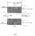
- Fig. 3 Processes that occur when the acid-eluent is generated are in Fig. 3 shown schematically.
- the ion source container 4 is filled with the solution containing concentrated anions; these should then become an eluant component.
- the ion source container is filled with a 1-2 mol / L concentrated nitric acid solution, for example potassium nitrate solution.
- an acid-eluting agent is generated, as a barrier 5 between the elution generating chamber 1 and the ion source container 4, the anion exchange membrane having the first electrode 6 in the form of an electron-conductive, porous palladium or platinum layer serving as the anode serves.
- the anion exchange membrane can only pass anions.
- the eluent generating chamber 1 is separated by the second electrode 7, which is carried out as an ion exchange membrane 8 having the electron-conductive porous layer 9.
- the electron-conducting palladium or platinum layer is coated on the outer side (with respect to the elution generating chamber) of the ion exchange membrane.
- a cation exchange membrane which only lets through cations is used as the ion exchange membrane 8.
- the separated oxygen is brought out through the porous layer 9 to the outside, since the ion exchange membrane 8 is gas-tight.
- the hydrogen ions formed as a result of the reaction are transferred to the elution generating chamber 1 through the cation exchange membrane.
- the decomposed in the electrolysis water in the membrane phase is replenished by adjusting the equilibrium upon contact of the membrane with the solution in the eluent generating chamber 1.
- the separated oxygen is brought out through the porous layer 9 to the outside, since the ion exchange membrane 8 is gas-tight.
- the hydroxide ions go into the solution. Since the concentration of nitrate ions in the solution is four to five times higher than the concentration of the hydroxide ions to be formed, nitrate ions are predominantly transferred into the elution generating chamber 1 (to maintain electrical neutrality) via the anion exchange membrane.
- a nitric acid solution is formed over the Outlet 3 flows out.
- the concentration of nitric acid at the outlet of the eluent producing chamber 1 is determined by the flow rate of the solution and the current value in the device.
- the nitric acid concentration in the generated eluent can be easily adjusted.
- an eluent is generated in the device that contains no dissolved gases and does not require degassing.
- the eluent then passes through the outlet end 3 in the ion chromatographic system.
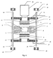
- the Fig. 4 schematically illustrates a possible assembly of the device.
- a housing 11 of the eluent generating chamber 1 is made in an inert, electrically non-conductive material in the form of a cylinder.
- the inlet end 2 and the outlet end 3 are arranged for the solution.
- the barrier 5 is arranged in the form of a disk whose diameter is greater than the inner housing diameter.
- the barrier 5 is an ion exchange membrane with the electron-conducting layer as the first electrode 6 on its surface.
- a ring 12 is placed in the lower part as a second electrode 7, on which a grid 13 is attached as an ion exchange membrane 8.
- the ring 12 and the grid 13 are made of metal, which is inert to the solutions used for dialysis, such as stainless steel, nickel (at cathode stress) or titanium (at anode stress).
- the ring with the grid functions as a current lead to the electron-conducting membrane surface and ensures a high breaking strength of the membrane at high pressures in the eluent generating chamber.
- the second electrode 7 is arranged in the form of a disc whose diameter is greater than the inner housing diameter.
- the second electrode 7 provides an ion exchange membrane 8 the electron-conducting layer 9 on its surface.
- a ring 14 is placed, on which a grid 15 is fixed.
- the ring 14 and the grid 15 are made of metal, which is inert to the solutions used for dialysis, such as stainless steel, nickel (at cathode stress) or titanium (at anode stress).
- the ring 14 with the grid 15 functions as a current supply to the electron-conducting membrane surface and ensures a high breaking strength of the membrane at high pressures in the eluent generating chamber 1.
- the chamber housing together with membranes and rings with grids is hermetically arranged by means of metal flanges 16 and 17, which are tightened with pins 18 and nuts 19.
- Flanges are made of the inert metal solutions used in dialysis, such as stainless steel, nickel (for cathode stress), or titanium (for anode stress).
- the pins 18 are made of non-conductive material.
- power supply lines 21 are attached to the power supply to the device.
- a barrier 5 with an electron-conducting layer on its surface makes it possible to install a metal ring with a grid, which ensures a high breaking strength of the membrane at high pressures in the elution-generating chamber 1.
- the membrane rupture strength at high pressures is ensured by a smaller barrier diameter (0.4-0.5 cm) and a greater thickness (3-5 mm) of the barrier.
- An additional heat source in the prototype device is the electrical resistance of the solution layer between the barrier 5 and the first electrode 6 in the ion source container 4 or the ion exchange resin layer with which the ion source container 4 is filled. In the device according to the invention, this heat source is missing (the first electrode 6 is arranged on the barrier surface).
- the evolution of gas in the eluent generating chamber 1 is absent and, as a consequence, there is no need for additional devices which eliminate the interfering influence of the dissolved gases on the process of chromatographic separation and detection.
Landscapes
- Immunology (AREA)
- Pathology (AREA)
- Life Sciences & Earth Sciences (AREA)
- Chemical & Material Sciences (AREA)
- Analytical Chemistry (AREA)
- Biochemistry (AREA)
- Health & Medical Sciences (AREA)
- General Health & Medical Sciences (AREA)
- Physics & Mathematics (AREA)
- General Physics & Mathematics (AREA)
- Separation Using Semi-Permeable Membranes (AREA)
- Medicines That Contain Protein Lipid Enzymes And Other Medicines (AREA)
- Physical Or Chemical Processes And Apparatus (AREA)
- Transition And Organic Metals Composition Catalysts For Addition Polymerization (AREA)
- Exhaust Gas After Treatment (AREA)
- Treatment Of Liquids With Adsorbents In General (AREA)
Description
- Die Erfindung gehört zum Bereich der ionenchromatografischen Analyse, und zwar zum Bereich von Einrichtungen zur Elutionsmittelerzeugung für die lonenchromatografie.
- Eines der wirksamsten Analyseverfahren von anionischen Komponenten in Wasserlösungen ist die Ionenchromatografie. Mit diesem Verfahren werden die zu bestimmenden Anionen der Probe in einer analytischen Säule mittels Alkalielutionsmitteln (Lösungen von schwachen Säuren und starken Basen, Hydroxiden der Alkalimetalle usw.) mit einer weiteren konduktometrischen Detektion getrennt. Obwohl Lösungen von Alkalimetallen bei der Trennung und Anionenanalyse die wirksamsten Elutionsmittel sind (ein wesentlich niedriges Niveau der Hintergrundleitfähigkeit des analytischen Signals nach der Unterdrückung, sicher prognostizierende Elutionsdaten, keine Systempeaks in den Chromatogrammen), ist ihre Anwendung bislang wegen der Komplexität der Zubereitung von reinen Hydroxidlösungen und der Aufrechterhaltung von Elutionsdaten beschränkt: ein beliebiger Elutionsmittelkontakt (bei der Zubereitung bzw. der Anwendung) mit Luft führt zu einer nicht beherrschbaren Änderung der Elutionsmitteldaten infolge einer Absorption des atmosphärischen CO2-Gases aus dem Elutionsmittel sowie zu einer Erhöhung der Hintergrundleitfähigkeit des Elutionsmittels nach dem Druckabbau.
- Bekannt ist eine Einrichtung zur diffusen Erzeugung eines Alkalielutionsmittels (W. S. Gurskij, L. A. Godon, S. W. Timofejew, Erzeuger für Hydroxidelutionsmittel zur ionenchromatografischen Anionenbestimmung, "Zh. Werkslabor", Band 63, Nr. 12, S. 11, 1997). In dieser Einrichtung wird hochreines Wasser durch Kationenaustauschkapillare geleitet, deren Außenfläche mit der konzentrierten Lösung einer Lauge, z. B. Kaliumhydroxid, in Berührung kommt. Unter der Wirkung des Konzentrationsgradienten diffundiert Kaliumhydroxid in das Innere der Kapillare, und am Kapillarenausgang wird Kaliumhydroxidlösung (Elutionsmittel) gebildet, die in eine Trennsäule wandert. Weil Karbonate von Alkalimetallen in konzentrierten Laugenlösungen praktisch nicht löslich sind, enthält das in der Einrichtung zu erzeugende Elutionsmittel (Kaliumhydroxidlösung) keine Karbonationen. Die Konzentration von Kaliumhydroxid im Elutionsmittel wird mittels der Flussrate des Elutionsmittels durch die Kapillare bestimmt und kann durch die Kontaktfläche der konzentrierten Kaliumhydroxidlösung mit der Kapillare variiert werden.
- Zu den Nachteilen der beschriebenen Einrichtung gehört, dass eine Vorrichtung zur Konstanthaltung der Temperatur nötig ist, da der diffuse Kaliumhydroxidfluss durch die Membran von der Temperatur abhängt. Außerdem kann die Einrichtung in der Elutionsmittellinie unter einem Druck von max. 3-4 at arbeiten und dementsprechend in der hydraulischen Linie des Hochdrucks in der Chromatografieeinrichtung (nach der Pumpe) nicht angeordnet werden.
- Wesentlich wirksamer sind Einrichtungen zur Elutionsmittelerzeugung, in denen das Elutionsmittel infolge der Übertragung der benötigten Ionen durch den lonenaustauscher unter der Wirkung eines elektrischen Felds erzeugt wird. In diesem Fall kann die Elutionsmittelkonzentration durch Änderung der elektrischen Parameter, beispielsweise der Stromstärke, einfach variiert werden.
- In der im
US-Patent 5 045 204 beschriebenen Einrichtung wird nicht gereinigte Säure bzw. Base durch die Kanalquelle und längs einer selektiven lonenaustauschmembran geleitet, die die Kanalquelle vom Produktkanal abgrenzt. Durch den Produktkanal wird hochreines Wasser geleitet. Die Membran erlaubt ein selektives Durchlassen von Kationen bzw. Anionen. Zwischen den Kanälen wird ein solches elektrisches Potential erzeugt, das Basenkationen bzw. Säureanionen aus dem ersten in den letzten Kanal zur Erzeugung einer Base oder einer Säure mit elektrolytisch gebildeten Hydroxid- bzw. Wasserstoff-lonen wandern lässt. Das im Elutionsmittel elektrolytisch ausscheidende Gas hindert eine weitere chromatografische Trennung und Detektion. Gemäß dem Patent wird das Elutionsmittel durch eine Entgasungseinrichtung geleitet, in der der Kanal mit dem Elutionsmittel von dem Kanal mit dem Gas mittels einer gasselektiven Membran getrennt wird, die Gas durchlässt und Flüssigkeit zurückhält. Infolgedessen wird der Elutionsmittelfluss beim Durchlassen durch die gasselektive Membran von Gas befreit. - Als Prototyp für die vorliegende Erfindung wurde eine Einrichtung zur Säure- oder Basenerzeugung nach dem
US-Patent 6 225 129 ausgewählt, die Folgendes enthält: - einen lonenquellenbehälter für Anionen bzw. Kationen,
- eine Kammer zur Erzeugung einer Säure oder Base, wobei die Kammer ein Einlaufende und ein Auslaufende aufweist,
- eine Barriere zwischen dem Ionenquellenbehälter und der Elutionsmittelerzeugungskammer (Säure oder Base), die das Wandern der Flüssigkeit aus der Erzeugungskammer in den Behälter und zurück verhindert und gleichzeitig die lonenübertragung gewährleistet, wobei Ionen nur mit einer negativen oder positiven Ladung übertragen werden,
- eine Wasserlösungsquelle, die mit dem Einlaufende der Elutionsmittelerzeugungskammer verbunden ist,
- eine Elektrode im lonenquellenbehälter,
- eine zweite Elektrode in der Elutionsmittelerzeugungskammer,
- eine Stromquelle, die das Anlegen einer Potentialdifferenz zur Übertragung von Kationen (Anionen) in der Erzeugungskammer der Base bzw. Säure unter Wirkung eines elektrischen Felds gewährleistet,
- eine Einrichtung zur Entgasung des Elutionsmittels.
- Die Einrichtung kann zur Erzeugung von Säure oder Base in einem chromatografischen System oder in einem anderen analytischen System, in dem hochreine Säuren oder Basen benötigt werden, eingesetzt werden.
- Nach Angabe der Erfinder des Patentprototyps übertrifft der von ihnen vorgeschlagene Elutionsmittelerzeuger die bislang bekannten Einrichtungen wesentlich. Die Vorteile sind gemäß dem Patent folgende:
- eine chromatografische Trennung kann nur mit dem entionisierten Wasser als Elutionsmittel durchgeführt werden; da die Säure oder Base benötigter Qualität on-line erzeugt wird, kann eine spezielle Bereitung des Elutionsmittels ausgeschlossen werden;
- die Elutionsfähigkeit (Konzentration der Säure oder Base) kann genau und bequem kontrolliert werden, indem der Strom in der Einrichtung zur Erzeugung der Säure oder Base und die Flussrate überwacht wird;
- möglich sind eine chromatografische Gradiententrennung mittels einer Änderung des Stroms im Laufe der Eluierung und eine Anwendung einer kostengünstigen Pumpe in einer isokratischen Arbeitsweise statt einer teuren Pumpe zur Gradienteneluierung;
- die Anwendung der Einrichtung zur Erzeugung der Säure oder Base ermöglicht, das chromatografische Verfahren zu verbessern, da das on-line zu erzeugende Elutionsmittel von Beimischungen frei ist, die oft bei einer "externen" Elutionsmittelbereitung eingebracht werden; das durch Sorption des CO2-Gases aus der Luft gewonnene Karbonat im Hydroxid-Elutionsmittel stört oft das chromatografische Verfahren. Dieses Problem wird durch den Einsatz eines on-line zu erzeugenden, hochreinen Hydroxid-Elutionsmittels gelöst.
- die Funktionssicherheit der Pumpen und deren Lebensdauer können erhöht werden, weil die Pumpe deionisiertes Wasser anstelle von korrosionsaggressiven Säuren und Basen pumpt;
- die Erfindung gemäß dem Patent stellt eine wesentliche Verbesserung bei der Erzeugung von Lösungen hochreiner Säuren und Basen für eine größere Zeitperiode zum Einsatz in der IC- und Flüssigchromatografie sowie für weitere Anwendungen sicher.
- Zugleich weist die Einrichtung nach dem Patent eine Reihe von Nachteilen auf. In erster Linie ist das eine in der Einrichtung erzeugte, hohe Wärmeentwicklung, die durch den hohen elektrischen Widerstand der Wasserlösungen, die an Elektrolysegasen reich sind, bedingt ist.
- Zur Verminderung der Wärmeentwicklung im System, insbesondere bei der benötigten Erzeugung der Elutionsmittel mit hoher Konzentration (bis 0,1 mol/l) wurden mehrere Ausführungsbeispiele der Einrichtung im Patent vorgeschlagen:
- es wurden zwei oder mehrere Ionenquellenbehältern eingesetzt, die mit der Elutionsmittelerzeugungskammer mittels zweier oder mehrerer Barrieren verbunden sind; der Vorteil beim Einsatz von zwei oder mehreren Kammern besteht darin, dass die im System herrschende Spannung dadurch vermindert werden kann, dass der zur Erzeugung von KOH eingesetzte Strom zwischen den einzelnen Kammern verteilt wird; somit können höhere Spannungen zur Erzeugung von Basen mit höherer Konzentration und gleichmäßigerer Entwicklung der Überschusswärme angelegt werden;
- in der Erzeugungskammer werden zwei oder mehrere Elektroden eingesetzt, die vorzugsweise längs der gesamten Kammerlänge in Richtung des Wasserflusses angeordnet sind, beispielsweise in der Nähe des Einlaufendes und Auslaufendes; dies vermindert den elektrischen Widerstand der Kammer und dementsprechend die Arbeitsspannung im System;
- es werden mehrere Barrieren in einem Behälter eingesetzt. Der Einsatz von mehreren Barrieren kann die Arbeitspannung der Einrichtung reduzieren. Als Folge kann in der Kammer der höhere Strom zur Erzeugung des Elutionsmittel in hoher Konzentration ohne Überschusswärmeentwicklung eingesetzt werden.
- Nichtsdestoweniger ist der Einsatz dieser Ausführungsbeispiele zur Verminderung der Wärmeentwicklung mit einem komplizierten Aufbau des Elutionsmittelerzeugers verbunden. Ein weiterer und wichtiger Nachteil des Prototyps ist die Gasentwicklung in der Elutionsmittelerzeugungskammer, die dazu führt, dass eine weitere, direkte, chromatografische Trennung unmöglich ist.
- Zur Beseitigung der störenden Wirkung der in der Elutionsmittelerzeugungskammer entwickelten Gase werden im Patentprototyp zwei Möglichkeiten genannt.
- Im ersten Fall wird eine Flussabgrenzung zur Druckerhöhung im gesamten chromatografischen System (Elutionsmittelerzeuger-Trennsäulen-Detektor) nach dem Detektor angeordnet. Bei Hochdruck (z. B. 70at und mehr) löst sich das Gas im Elutionsmittel quasi völlig und beeinflusst den Lauf des chromatografischen Prozesses der Trennung und Detektion unwesentlich. Dieses Verfahren benötigt einen Detektor mit einer Durchflusszelle, die einem hohen Druck von 70at und mehr widerstehen kann. In der IC mit Unterdrückung der Elutionsmittelleitfähigkeit fordert das oben beschriebene Verfahren, dass auch der Suppressor dem Druck von 70at und mehr widerstehen kann. Dies macht den Detektor- und Suppressoraufbau wesentlich kompliziert und erlaubt keine chromatografische Standardsysteme einzusetzen.
- Eine weitere Problemlösung der Gasentwicklung besteht in der Anordnung einer zusätzlichen Einrichtung zur Entgasung der Lösung nach dem Elutionsmittelerzeuger. Der Elutionsmittelfluss zusammen mit dem gelösten Gas wandert nach dem Elutionsmittelerzeuger unter Hochdruck in die polymerische Kapillare. Das Gas dringt durch die Kapillarwände hindurch. Von der Außenseite der gasselektiven Kapillare, die in einem Schutzrohr angeordnet ist, strömt die Flüssigkeit. Das durch die Kapillarwände diffundierte Gas wird durch eine Flüssigkeitsströmung beseitigt, die gleichzeitig die Adsorption des Kohlenwasserstoffdioxids aus der Umgebung in das Elutionsmittel verhindert.
- Prototypgemäß soll in jedem Fall eine zusätzliche Einrichtung zur Entgasung des Elutionsmittels bzw. zur Beseitigung der störenden Wirkung des Elutionsmittels eingesetzt oder erhöhte Forderungen an die Elemente des chromatografischen Messkanals gestellt werden.
- Die vorliegende Erfindung bezweckt die Beseitigung der beschriebenen Nachteile. Das gesetzte Ziel wird dadurch erreicht, dass im elektrodialytischen Elutionsmitteler zeuger zur IC vorgesehen ist:
- ein lonenquellenbehälter für Anionen bzw. Kationen,
- eine Elutionsmittelerzeugungskammer zur Erzeugung einer Säure oder Base, die ein Einlaufende und ein Auslaufende aufweist,
- eine Barriere zwischen dem lonenquelllenbehätter und der Elutionsmittelerzeugungskammer (Säure oder Base), die das Wandern von Flüssigkeit aus der Elutionsmittelerzeugungskammer in den lonenqullenbehälter und zurück verhindert und gleichzeitig die lonenübertragung gewährleistet, wobei Ionen nur mit einer negativen oder positiven Ladung übertragen werden,
- eine Wasserlösungsquelle, die mit dem Einlaufende der Elutionsmittelerzeugungskammer verbunden ist,
- eine erste Elektrode im lonenquellenbehäfter,
- eine zweite Elektrode in der Elutionsmittelerzeugungskammer,
- eine Stromquelle, die das Anlegen einer Potentialdifferenz zur Übertragung von Kationen (Anionen) in die Erzeugungskammer der Base bzw. Säure unter der Wirkung eines elektrischen Felds gewährleistet,
- eine erste Elektrode in der Elutionsmittelkammer in Form einer lonenaustauschmembran, auf deren Oberfläche eine elektronenleitende Schicht aufgetragen ist, wobei die lonenaustauschmembran als Außenwand der Elutionsmittelerzeugungskammer dient und gegenüber der Barriere liegt, die den lonenquellenbehälter von der Elutionsmittelerzeugungskammer trennt, wobei ferner die elektronenleitende Schicht auf der Außenseite (in Bezug auf die Elutionsmittelerzeugungskammer) der Ionenaustauschmembran liegt und die Elektrode im lonenqullenbehälter der Kationen- bzw. Anionenquelle in Form einer elektronenleitenden Schicht gestaltet ist, die auf der Oberfläche der den lonenqullenbehälter der Ionen/Kationenquelle von der Elutionsmittelerzeugungskammer trennenden Barriere liegt, wobei ferner die elektronenleitende Schicht auf der Außenseite der Barriere (in Bezug auf die Elutionsmittelerzeugungskammer) angeordnet ist und wobei die elektronenleitenden Schichten porös und aus Palladium oder Platin ausgeführt sind.
- Die Erfindung wird durch Zeichnungen erläutert, die schematisch die Einrichtungen gemäß der Erfindung, den Zusammenbau dieser Einrichtungen und die in der Einrichtung laufenden Prozesse darstellen. Es zeigen:
- Fig. 1
- eine schematische Darstellung einer Einrichtung gemäß der Erfin-dung,
- Fig. 2
- schematische Prozesse, die in der Einrichtung bei Erzeugung des Alkali-Elutionsmittels ablaufen,
- Fig. 3
- schematische Prozesse, die in der Einrichtung bei Erzeugung des Säure-Elutionsmittels ablaufen,
- Fig. 4
- schematisch einen möglichen Zusammenbau der Einrichtung.
- In
Fig.1 ist eine Elutionsmittelerzeugungskammer 1 mit einem Einlaufende 2 und einem Auslaufende 3 von einem lonenquellenbehälter 4 mittels einer Barriere 5 getrennt, die eine lonenaustauschmembran bildet. Die Barriere 5 ist für den Lösungsfluss undurchlässig und besitzt die Eigenschaft, nur gleich geladene Ionen durchzulassen. Auf die Barrierenoberfläche, die zum lonenquellenbehälter 4 ausgerichtet ist, ist eine erste Elektrode 6 in Form einer elektronenleitenden, porösen Schicht angeordnet. Auf der der Barriere 5 gegenüberliegenden Seite ist die Elutionsmittelerzeugungskammer 1 durch eine zweite Elektrode 7 begrenzt. Die zweite Elektrode 7 ist in Form einer lonenaustauschmembran 8 mit einseitiger, elektronenleitender, poröser Beschichtung 9 ausgeführt. Die elektronenleitende, poröse Schicht ist auf die Außenseite (in Bezug auf die Elutionsmittelerzeugungskammer) der lonenaustauschmembran aufgetragen. Die Elektroden 6, 7 sind an eine Speisequelle 10 angeschlossen. - Die elektronenleitenden Schichten werden auf die Oberfläche der lonenaustauschmembran mittels chemischer Ablagerung aufgetragen. Als elektronenleitende Schichten werden Schichten aus Platin oder Palladium benutzt. Die Auswahl des Materials ist durch eine hohe chemische Beständigkeit von Platin und Palladium als Anode oder Kathode in den eingesetzten Lösungen bedingt. Zur elektronenleitenden, porösen Beschichtung kann beispielsweise folgendes Verfahren benutzt werden. Die Membran wird im Laufe von 1-2 Stunden in Wasser bis zur Quellung gewässert. Danach wird die mit einer Metallschicht beschichtete Membran in Kontakt mit einer Lösung folgender Zusammensetzung gebracht:
5g/l Palladiumchlorid,
100g/l Ammoniumhydroxid,
20min Kontaktzeit. - Danach wird die Membranoberfläche mit Wasser durchgespült und kommt für eine Minute lang in Kontakt mit einer bis 80°C erwärmten Hydrasinlösung (100g/l). Als Ergebnis bildet sich auf der Membranoberfläche eine katalytische Palladiumschicht.
- Zur elektronenleitenden Palladiumbeschichtung wird die Membranoberfläche mit der aufgetragenen katalytischen Schicht in Kontakt mit einer Lösung folgender Zusammensetzung gebracht:
4g/l Palladiumchlorid,
300ml/l Ammoniumhydroxid (25%),
12g/l Trilon B,
2g/l Hydrasin. - Die Temperatur der Lösung beträgt 20 °C. Das Hydrasin wird der Lösung unmittelbar vor dem Einsatz zugegeben. Die Kontaktzeit der Membranoberfläche mit der Lösung beträgt 2-4 Stunden. Eine kürzere Kontaktzeit führt zur Bildung einer elektronenleitenden Schicht mit einem hohen elektrischen Widerstand. Eine längere Kontaktzeit führt zur Bildung einer nicht porösen Palladiumschicht, die die Ionenübertragung durch die Membran behindert.
- Zur elektronenleitenden Platinbeschichtung wird die Membranoberfläche mit der aufgetragenen, katalytischen Palladiumschicht in Kontakt mit einer Lösung folgender Zusammensetzung gebracht:
40g/l (NH4)2PtCl6,
320g/l NH4Cl. - Die Temperatur der Lösung beträgt 50 °C. Die Kontaktzeit der Membranoberfläche mit der Lösung beträgt 2-4 Stunden. Eine kürzere Kontaktzeit führt zur Bildung einer elektronenleitenden Schicht mit einem hohen elektrischen Widerstand. Eine längere Kontaktzeit führt zur Bildung einer nicht porösen Platinschicht, die die lonenübertragung durch die Membran behindert.
- Verfahren, die im Laufe der Alkali-Elutionsmittelerzeugung in der Einrichtung gemäß der Erfindung ablaufen, sind schematisch in
Fig. 2 dargestellt. Der Behälter 4 wird mit einer konzentrierten, Kationen enthaltenden Lösung gefüllt, wobei die Kationen dann zu einem Elutionsmittelbestandteil werden sollen. Wenn die Kaliumhydroxidlösung erzeugt wird, wird der Behälter mit der konzentrierten Kaliumhydroxid- bzw. Kaliumsalzlösung, beispielsweise Kaliumphosphatlösung, gefüllt. Falls ein Alkali-Elutionsmittel erzeugt wird, dient als Barriere zwischen der Erzeugungskammer und dem Behälter die Kationenaustauschmembran auf der Basis von beispielsweise perfluoriertem Schwefelpolymer mit der Elektrode 6 in Form einer elektronenleitenden Palladium- bzw. Platinschicht, die die Anode darstellt. Die Kationenaustauschmembran kann nur Kationen durchlassen. - Auf der der Barriere 5 gegenüberliegenden Seite ist die Elutionsmittelerzeugungskammer 1 durch die zweite Elektrode 7 getrennt, die als lonenaustauschmembran 8 mit der elektronenleitenden, porösen Schicht 9 ausgeführt ist. Die elektronenleitende Palladium- bzw. Platinschicht ist auf die äußere Seite (in Bezug auf Elutionsmittelerzeugungskammer) der Ionenaustauschmembran aufgetragen. Bei der Erzeugung eines Alkali-Elutionsmittel wird als Ionenaustauschmembran 8 eine Anionenaustauschmembran eingesetzt, die nur Anionen durchlässt.
- In die Elutionsmittelerzeugungskammer 1 wird über das Einlaufende 2 Wasser geleitet. Wenn eine elektrische Spannung zwischen den Elektroden angelegt wird, läuft auf der zweiten Elektrode 7 (Kathode) folgende Zersetzungsreaktion des Wassers ab, das sich in der Membranphase befindet:
2H2O + 2e- → 2OH- + H2↑ - Der abgeschiedene Wasserstoff wird über die poröse Schicht 9 nach außen gebracht, da die lonenaustauschmembran 8 gasdicht ist. Infolge der Reaktion werden die Hydroxidionen über die Anionenaustauschmembran in die Elutionsmittelerzeugungskammer 1 übertragen. Das bei der Elektrolyse zersetzte Wasser in der Membranphase wird durch Einstellung des Gleichgewichts beim Kontakt der Membran mit der Lösung in der Elutionsmittelerzeugungskammer 1 nachgefüllt.
- Gleichzeitig läuft an der ersten Elektrode 6 (Anode) folgende Wasserzersetzungsreaktion ab:
H2O - 2e-→2H+ + ½O2 ↑ - Der abgeschiedene Sauerstoff wird über die elektronenleitende, poröse Schicht 6 und die Lösungsschicht im lonenquellenbehälter 4 nach außen gebracht, da die lonenaustauschmembran gasdicht ist. Wasserstoffionen gehen in die Lösung über. Da die Konzentration der Kaliumionen in der Lösung vier- bis fünfmal höher als die Konzentration der bei der Elektrolyse gebildeten Wasserstoffionen ist, werden in die Elutionsmittelerzeugungskammer 1 (zur Erhaltung der elektrischen Neutralität) durch die Kationenaustauschmembran überwiegend Kaliumionen übertragen. Der größte Teil der auf der Elektrode gebildeten Wasserstoffionen wird von dem abgeschiedenen Sauerstoff durch eine intensive Mischung der an der Elektrode liegenden Schicht ins Innere der Lösung transportiert. In der Lösung wirken die Wasserstoffionen mit den Hydroxidionen unter Wasserbildung zusammen.
- Als Ergebnis wird in der Elutionsmittelerzeugungskammer 1 eine Kaliumhydroxidlösung erzeugt, die aus dem Auslaufende 3 ausfließt. Die Kaliumhydroxidkonzentration am Auslaufende 3 der Elutionsmittelerzeugungskammer 1 wird durch die Flussrate der Lösung und den Stromwert in der Einrichtung bestimmt. Durch Änderung des Stromwerts in der Einrichtung kann die Kaliumhydroxidkonzentration im erzeugten Elutionsmittel leicht eingestellt werden. Somit wird in der Einrichtung ein Etutionsmittel erzeugt, das keine gelösten Gase enthält und keine Entgasung braucht. Das Elutionsmittel gelangt dann über das Auslaufende 3 in das ionenchromatografische System.
- Prozesse, die bei Erzeugung des Säure-Elutionsmittels ablaufen, werden in
Fig. 3 schematisch dargestellt. Der lonenqueltenbehälter 4 wird mit der konzentrierte Anionen enthaltenden Lösung gefüllt; diese sollen dann zu einem Elutionsmittelbestandteil werden. Wenn Salpetersäurelösung erzeugt wird, wird der lonenquellenbehälter mit einer 1-2mol/l-konzentrierten Salpetersäurelösung, beispielsweise Kaliumnitratlösung, gefüllt. Falls ein Säure-Elutionsmittel erzeugt wird, dient als Barriere 5 zwischen der Elutionsmittelerzeugungskammer 1 und dem lonenquellenbehälter 4 die Anionenaustauschmembran mit der ersten Elektrode 6 in Form einer elektronenleitenden, porösen Palladium- bzw. Platinschicht, die die Anode darstellt. Die Anionenaustauschmembran kann nur Anionen durchlassen. - Auf der der Barriere 5 gegenüberliegenden Seite ist die Elutionsmittelerzeugungskammer 1 durch die zweite Elektrode 7 getrennt, die als lonenaustauschmembran 8 mit der elektronenleitenden, porösen Schicht 9 ausgeführt wird. Die elektronenleitende Palladium- bzw. Platinschicht ist auf der äußere Seiten (in Bezug auf Elutionsmittelerzeugungskammer) der Ionenaustauschmembran aufgetragen. Bei der Erzeugung eines Säure-Elutionsmittels wird als Ionenaustauschmembran 8 eine Kationaustauschmembran eingesetzt, die nur Kationen durchlässt.
- In die Elutionsmittelerzeugungskammer 1 wird über das Einlaufende 2 Wasser geleitet. Beim Anlegen einer elektrischen Spannung läuft an der zweiten Elektrode 7 (Anode) folgende Zersetzungsreaktion des Wassers ab, das sich in der Membranphase befindet:
H2O - 2e- →2H+ + ½O2↑ - Der abgeschiedene Sauerstoff wird über die poröse Schicht 9 nach außen gebracht, da die Ionenaustauschmembran 8 gasdicht ist. Die infolge der Reaktion gebildeten Wasserstofftonen werden über die Kationenaustauschmembran in die Elutionsmittelerzeugungskammer 1 übertragen. Das bei der Elektrolyse zersetzte Wasser in der Membranphase wird durch Einstellung des Gleichgewichts beim Kontakt der Membran mit der Lösung in der Elutionsmittelerzeugungskammer 1 nachgefüllt.
- Gleichzeitig läuft an der ersten Elektrode 6 (Kathode) folgende Wasserzersetzungsreaktion ab:
2H2O + 2e- → 2OH-+ H2 ↑ - Der abgeschiedene Sauerstoff wird über die poröse Schicht 9 nach außen gebracht, da die lonenaustauschmembran 8 gasdicht ist. Die Hydroxidionen gehen in die Lösung über. Da die Konzentration der Nitrationen in der Lösung vier- bis fünfmal höher als die Konzentration der zu bildenden Hydroxidionen ist, werden in die Elutionsmittelerzeugungskammer 1 (zur Erhaltung der elektrischen Neutralität) über die Anionenaustauschmembran überwiegend Nitrationen übertragen. Als Ergebnis bildet sich in der Elutionsmittelerzeugungskammer 1 eine Salpetersäurelösung, die über den Auslauf 3 ausfließt. Die Konzentration der Salpetersäure am Auslauf der Elutionsmittelerzeugungskammer 1 wird durch die Flussrate der Lösung und den Stromwert in der Einrichtung bestimmt. Durch Änderung des Stromwerts in der Einrichtung kann die Salpetersäurekonzentration im erzeugten Elutionsmittel leicht eingestellt werden. Somit wird in der Einrichtung ein Elutionsmittel erzeugt, das keine gelösten Gase enthält und keine Entgasung braucht. Das Elutionsmittel gelangt dann über das Auslaufende 3 in das ionenchromatografische System.
- Die
Fig. 4 stellt einen möglichen Zusammenbau der Einrichtung schematisch dar. Ein Gehäuse 11 der Elutionsmittelerzeugungskammer 1 wird in einem inerten, elektrisch nicht leitenden Material in Form eines Zylinders ausgeführt. Auf der Seitenoberfläche sind das Einlaufende 2 und das Auslaufende 3 für die Lösung angeordnet. Im oberen Gehäuseabschnitt ist die Barriere 5 in Form einer Scheibe angeordnet, deren Durchmesser größer als der innere Gehäusedurchmesser ist. Die Barriere 5 stellt eine lonenaustauschmembran mit der elektronleitenden Schicht als erste Elektrode 6 auf ihrer Oberfläche dar. Auf die Barriere 5 ist im unteren Teil ein Ring 12 als zweite Elektrode 7 aufgesetzt, auf dem ein Gitter 13 als lonenaustauschmembran 8 befestigt ist. Der Ring 12 und das Gitter 13 bestehen aus Metall, das gegenüber den zur Dialyse eingesetzten Lösungen inert ist, beispielsweise rostfreier Stahl, Nickel (bei Kathodenbeanspruchung) oder Titan (bei Anodenbeanspruchung). Der Ring mit dem Gitter arbeitet als Stromzuführung zur elektronenleitenden Membranoberfläche und stellt eine hohe Bruchfestigkeit der Membran bei hohen Drucken in der Elutionsmittelerzeugungskammer sicher. - Im unteren Gehäuseabschnitt ist gegenüber der Barriere 5 die zweite Elektrode 7 in Form einer Scheibe angeordnet, deren Durchmesser größer als der innere Gehäusedurchmesser ist. Die zweite Elektrode 7 stellt eine lonenaustauschmembran 8 mit der elektronenleitenden Schicht 9 auf ihrer Oberfläche dar. Auf die zweite Elektrode 7 wird ein Ring 14 aufgesetzt, auf dem ein Gitter 15 befestigt ist. Der Ring 14 und das Gitter 15 bestehen aus Metall, das gegenüber den zur Dialyse eingesetzten Lösungen inert ist, beispielsweise rostfreier Stahl, Nickel (bei Kathodenbeanspruchung) oder Titan (bei Anodenbeanspruchung). Der Ring 14 mit dem Gitter 15 arbeitet als Stromzuführung zur elektronenleitenden Membranoberfläche und stellt eine hohe Bruchfestigkeit der Membran bei hohen Drucken in der Elutionsmittelerzeugungskammer 1 sicher.
- Das Kammergehäuse zusammen mit Membranen und Ringen mit Gittern wird mittels Metallflansche 16 und 17, die mit Stiften 18 und Muttern 19 zusammengezogen werden, in einer einheitlichen Einrichtung hermetisch angeordnet. Flansche sind gegen die in der Dialyse eingesetzten Lösungen aus inertem Metall gefertigt, beispielsweise rostfreier Stahl, Nickel (bei Kathodenbeanspruchung) oder Titan (bei Anodenbeanspruchung). Die Stifte 18 sind aus nicht leitfähigem Material gefertigt. An den Flanschen 16, 17 sind Stromversorgungsleitungen 21 zur Stromzufuhr zur Einrichtung befestigt. An den oberen Flansch 16 ist der lonenquellenbehälter 4 mit einer Öffnung 20 zur Abfuhr der bei der Elektrolyse entwickelten Gase hermetisch, beispielsweise mittels Schraubverbindungen, angeordnet.
- Im Unterschied zum Prototyp ermöglicht der Einsatz einer Barriere 5 mit einer elektronleitenden Schicht auf deren Oberfläche, einen Metallring mit Gitter zu installieren, der eine hohe Bruchfestigkeit der Membran bei hohen Drucken in der Elutionsmittelerzeugungskammer 1 gewährleistet. In der Prototyp-Einrichtung wird die Membranbruchfestigkeit bei hohen Drucken durch einen kleineren Barrieredurchmesser (0,4-0,5 cm) und eine größere Dicke (3-5 mm) der Barriere gewährleistet. Diese beiden Faktoren führen zum Anstieg der Spannung im System (bei dem vorgegebenen Strom) und als Folge zum Anstieg der Wärmeentwicklung in der Einrichtung. In der Einrichtung gemäß der Erfindung ist es möglich, eine Barriere 5 mit einem Durchmesser von 1,0-3,0 cm und einer Dicke von 0,5-1,0 mm einzusetzen. In diesem Fall steigt der elektrische Widerstand der Barriere 5 selbst bei sonst gleichen Voraussetzungen dreißig- bis hundertmal an.
- Eine zusätzliche Wärmequelle in der Prototyp-Einrichtung ist der elektrische Widerstand der Lösungsschicht zwischen der Barriere 5 und der ersten Elektrode 6 im lonenquellenbehälter 4 oder der Schicht aus einem Ionenaustauschharz, mit dem der lonenquellenbehäfter 4 gefüllt ist. Bei der Einrichtung gemäß der Erfindung fehlt diese Wärmequelle (die erste Elektrode 6 wird an der Barrierenoberfläche angeordnet).
- Bei der Einrichtung gemäß der Erfindung fehlt die Gasentwicklung in der Elutionsmittelerzeugungskammer 1 und als Folge fehlt die Notwendigkeit zusätzlicher Vorrichtungen, die den störenden Einfluss der gelösten Gase auf den Prozess der chromatografischen Trennung und Detektion beseitigen.
-
- 1. W. S. Gurskij, L. A. Godon, S. W. Timofejew, Erzeugung von Hydroxid-Elutionsmitteln zur ionenchromatografischen Anionenbestimmung, "Sch. Werkslabor", Band 63, Nr. 12, S.11, 1997
- 2.
US-Patent 5 45 204 - 3.
US-Patent 6 225 129
Claims (5)
- Elektrodialytischer Elutionsmittelerzeuger zur lonenchromatografie, der Folgendes aufweist:- einen Ionenquellenbehälter (4),- eine Elutionsmittelerzeugungskammer (1) zur Elutionsmittelerzeugung, die ein Einlaufende (2) und ein Auslaufende (3) aufweist,- eine Barriere (5) zwischen dem lonenquellenbehälter (4) und der Elutionsmittelerzeugungskammer (1), wobei diese Barriere (5) das Wandern der Flüssigkeit aus der Elutionsmittelerzeugungskammer (1) in den lonenquellenbehälter (4) und zurück verhindert, gleichzeitig die lonenübertragung gewährleistet und in Form einer lonenaustauschmembran ausgeführt ist,- eine Wasserlösungsquelle, die mit dem Einlaufende (2) der Elutionsmittelerzeugungskammer (1) verbunden ist,- eine erste Elektrode (6) im lonenquellenbehälter (4),- eine zweite Elektrode (7) in der Elutionsmittelerzeugungskammer (1), die gegenüber der ersten Elektrode (6) angeordnet ist,- eine Stromquelle (10), die das Anlegen einer Spannung zwischen den Elektroden (6, 7) zur Übertragung von lonen in die Elutionsmittelerzeugungskammer (1) unter der Wirkung eines elektrischen Felds gewährleistet,dadurch gekennzeichnet,
dass die zweite Elektrode (7) ebenfalls als Ionenaustauschmembran (8) mit einer elektronenleitenden Schicht auf ihrer Oberfläche ausgebildet ist, wobei die lonenaustauschmembran (8) als Außenseite der Elutionsmittelerzeugungskammer (1) dient und die leitfähige Schicht auf die Außenseite der lonenaustauschmembran (8) in Bezug auf die Elutionsmittelerzeugungskammer (1) und auf die Gegenseite in Bezug auf die Barriere (5) aufgetragen ist. - Elutionsmittelerzeuger nach Anspruch 1,
dadurch gekennzeichnet,
dass die erste Elektrode (6) im lonenquellenbehälter (4) in Form einer elektronenleitenden Schicht ausgebildet ist, die auf die Oberfläche der den lonenquellenbehälter (4) von der Elutionsmittelerzeugungskammer (1) trennenden Barriere (5) aufgetragen ist, wobei die elektronenleitende Schicht auf die Außenseite der Oberfläche der Barriere (5) in Bezug auf die Elutionsmittelerzeugungskammer (1) aufgetragen ist. - Elutionsmittelerzeuger nach Anspruch 1 oder 2,
dadurch gekennzeichnet,
dass die elektronenleitenden Schichten aus Palladium bzw. Platin bestehen. - Elutionsmittelerzeuger nach einem der Ansprüche 1 bis 3,
dadurch gekennzeichnet,
dass die elektronenleitenden Schichten porös ausgebildet sind. - Elutionsmittelerzeuger nach einem der Ansprüche 1 bis 4,
dadurch gekennzeichnet,
dass auf die elektronenleitenden Schichten ein Metallgitter (13, 15) aus rostfreiem Stahl bei Kathodenbeanspruchung bzw. aus Titan bei Anodenbeanspruchung aufgesetzt ist.
Applications Claiming Priority (2)
| Application Number | Priority Date | Filing Date | Title |
|---|---|---|---|
| RU2003132803/28A RU2229325C1 (ru) | 2003-11-12 | 2003-11-12 | Электродиализный генератор элюента для ионной хроматографии |
| PCT/RU2004/000025 WO2005046833A1 (en) | 2003-11-12 | 2004-03-10 | Electrodialysis eluent generator for ion chromatography |
Publications (3)
| Publication Number | Publication Date |
|---|---|
| EP1685887A1 EP1685887A1 (de) | 2006-08-02 |
| EP1685887A4 EP1685887A4 (de) | 2007-06-13 |
| EP1685887B1 true EP1685887B1 (de) | 2009-05-27 |
Family
ID=32679747
Family Applications (1)
| Application Number | Title | Priority Date | Filing Date |
|---|---|---|---|
| EP04719163A Expired - Lifetime EP1685887B1 (de) | 2003-11-12 | 2004-03-10 | Elektrodialyseeluationsmittelgenerator für ionenchromatographie |
Country Status (6)
| Country | Link |
|---|---|
| EP (1) | EP1685887B1 (de) |
| AT (1) | ATE432116T1 (de) |
| DE (1) | DE502004009538D1 (de) |
| ES (1) | ES2331070T3 (de) |
| RU (1) | RU2229325C1 (de) |
| WO (1) | WO2005046833A1 (de) |
Families Citing this family (3)
| Publication number | Priority date | Publication date | Assignee | Title |
|---|---|---|---|---|
| US8475639B2 (en) | 2007-12-06 | 2013-07-02 | Dionex Corporation | Titration device and method |
| US11598014B2 (en) | 2020-10-02 | 2023-03-07 | Dionex Corporation | Electrolytic remote ion source and ion recycle (ISIR) module |
| US12247307B2 (en) * | 2021-12-30 | 2025-03-11 | Dionex Corporation | Configuration for ultra high pressure electrolytic eluent generators |
Family Cites Families (6)
| Publication number | Priority date | Publication date | Assignee | Title |
|---|---|---|---|---|
| SU1741852A1 (ru) * | 1989-11-27 | 1992-06-23 | Тамбовский Филиал Опытно-Конструкторского Бюро Нестандартного Оборудования И Разработки Технологических Процессов | Способ получени кислоты и щелочи |
| US5045204A (en) * | 1990-02-13 | 1991-09-03 | Dionex Corporation | Method and apparatus for generating a high purity chromatography eluent |
| US6027643A (en) * | 1997-09-04 | 2000-02-22 | Dionex Corporation | Ion chromatographic method and apparatus using a combined suppressor and eluent generator |
| US6225129B1 (en) * | 1998-02-02 | 2001-05-01 | Dionex Corporation | Large capacity acid or base generation apparatus and method of use |
| US20030127392A1 (en) * | 2002-01-10 | 2003-07-10 | Kannan Srinivasan | Eluent purifier and method of use |
| RU2229326C1 (ru) * | 2003-11-12 | 2004-05-27 | ЗАО "Научно-Производственная Коммерческая Фирма Аквилон" | Электродиализный подавитель для ионной хроматографии (варианты) |
-
2003
- 2003-11-12 RU RU2003132803/28A patent/RU2229325C1/ru not_active IP Right Cessation
-
2004
- 2004-03-10 EP EP04719163A patent/EP1685887B1/de not_active Expired - Lifetime
- 2004-03-10 DE DE502004009538T patent/DE502004009538D1/de not_active Expired - Lifetime
- 2004-03-10 WO PCT/RU2004/000025 patent/WO2005046833A1/ru not_active Ceased
- 2004-03-10 AT AT04719163T patent/ATE432116T1/de not_active IP Right Cessation
- 2004-03-10 ES ES04719163T patent/ES2331070T3/es not_active Expired - Lifetime
Also Published As
| Publication number | Publication date |
|---|---|
| EP1685887A4 (de) | 2007-06-13 |
| RU2229325C1 (ru) | 2004-05-27 |
| ES2331070T3 (es) | 2009-12-21 |
| EP1685887A1 (de) | 2006-08-02 |
| DE502004009538D1 (en) | 2009-07-09 |
| WO2005046833A1 (en) | 2005-05-26 |
| ATE432116T1 (de) | 2009-06-15 |
Similar Documents
| Publication | Publication Date | Title |
|---|---|---|
| DE3153213C2 (de) | ||
| DE60035952T2 (de) | Stromeffiziente suppressoren und verfahren zu deren verwendung | |
| DE69330654T2 (de) | Ionenchromatographie unter Verwendung von elektrochemischer Unterdrückung und Detektorausflussrückführung | |
| DE69610597T2 (de) | Verfahren und vorrichtung zur elektrochemischen veränderung von chromatographiematerial | |
| DE60318455T2 (de) | Elektrolytischer generator zur herstellung von eluierungsmittel und dessen verwendung | |
| DE69608187T2 (de) | Zwischenzeitliche regenerierung eines elektrolytischen schüttgutbettes für ionenchromatographie | |
| EP0069285A1 (de) | Verfahren und Vorrichtung zur quantitativen Bestimmung von Kationen oder Anionen durch Ionenchromatographie | |
| DE69825860T2 (de) | Ionenchromatographische methode und vorrichtung mit einem kombinierten suppressor- und elutionsmittel- erzeuger | |
| DE3049982C2 (de) | ||
| DE69635729T2 (de) | Intermittierende elektrolytische regenerierung eines membransuppressors für ionenchromatographie | |
| EP0442224A2 (de) | Verfahren und Vorrichtung zum Erzeugen eines hochreinen chromatographischen Eluenten | |
| EP0068522A1 (de) | Verfahren und Vorrichtung zur synthetischen Herstellung von Ozon durch Elektrolyse und deren Verwendung | |
| DE60025119T2 (de) | Verfahren zur Gasentfernung vor der Probendetektion | |
| DE1199520B (de) | Coulometrisches Titriergeraet | |
| DE102016117998A1 (de) | Vorrichtung für den Nachweis von organischen Verbindungen | |
| DE69028495T2 (de) | Fühler für ionisierbare Substanzen | |
| DE69726023T2 (de) | Ionenchromatographische methode und vorrichtung mit ionenrückfluss | |
| EP1685887B1 (de) | Elektrodialyseeluationsmittelgenerator für ionenchromatographie | |
| DE2301032A1 (de) | Verfahren und vorrichtung zur herstellung von oxalsaeure durch elektrochemische reduktion von kohlendioxid | |
| DE69029446T2 (de) | Vorrichtung und Verfahren zur Minimierung der Effekte, des in einem Elektrolyten gelösten Sauerstoffgehaltes, bei Analysatoren für niedrige Sauerstoffkonzentrationen | |
| US20250198019A1 (en) | Configuration for ultra high pressure electrolytic eluent generators | |
| EP0780685A1 (de) | Amperometrischer Zweielektrodensensor, insbesondere für Wasserstoffperoxid | |
| DE69322243T2 (de) | Elektrochemische vorbehandlungsvorrichtung zur analyse von flüssigen proben | |
| EP1685886A1 (de) | Elektrodialysesuppressor für ionenchromatographie | |
| DE4414688A1 (de) | Röntgenstrahler mit Schutzgehäuse |
Legal Events
| Date | Code | Title | Description |
|---|---|---|---|
| PUAI | Public reference made under article 153(3) epc to a published international application that has entered the european phase |
Free format text: ORIGINAL CODE: 0009012 |
|
| 17P | Request for examination filed |
Effective date: 20060612 |
|
| AK | Designated contracting states |
Kind code of ref document: A1 Designated state(s): AT BE BG CH CY CZ DE DK EE ES FI FR GB GR HU IE IT LI LU MC NL PL PT RO SE SI SK TR |
|
| DAX | Request for extension of the european patent (deleted) | ||
| A4 | Supplementary search report drawn up and despatched |
Effective date: 20070511 |
|
| 17Q | First examination report despatched |
Effective date: 20080328 |
|
| GRAP | Despatch of communication of intention to grant a patent |
Free format text: ORIGINAL CODE: EPIDOSNIGR1 |
|
| GRAS | Grant fee paid |
Free format text: ORIGINAL CODE: EPIDOSNIGR3 |
|
| GRAA | (expected) grant |
Free format text: ORIGINAL CODE: 0009210 |
|
| AK | Designated contracting states |
Kind code of ref document: B1 Designated state(s): AT BE BG CH CY CZ DE DK EE ES FI FR GB GR HU IE IT LI LU MC NL PL PT RO SE SI SK TR |
|
| REG | Reference to a national code |
Ref country code: GB Ref legal event code: FG4D |
|
| REG | Reference to a national code |
Ref country code: CH Ref legal event code: EP |
|
| REG | Reference to a national code |
Ref country code: IE Ref legal event code: FG4D Free format text: LANGUAGE OF EP DOCUMENT: GERMAN |
|
| REF | Corresponds to: |
Ref document number: 502004009538 Country of ref document: DE Date of ref document: 20090709 Kind code of ref document: P |
|
| PG25 | Lapsed in a contracting state [announced via postgrant information from national office to epo] |
Ref country code: FI Free format text: LAPSE BECAUSE OF FAILURE TO SUBMIT A TRANSLATION OF THE DESCRIPTION OR TO PAY THE FEE WITHIN THE PRESCRIBED TIME-LIMIT Effective date: 20090527 Ref country code: PT Free format text: LAPSE BECAUSE OF FAILURE TO SUBMIT A TRANSLATION OF THE DESCRIPTION OR TO PAY THE FEE WITHIN THE PRESCRIBED TIME-LIMIT Effective date: 20090927 |
|
| NLV1 | Nl: lapsed or annulled due to failure to fulfill the requirements of art. 29p and 29m of the patents act | ||
| PG25 | Lapsed in a contracting state [announced via postgrant information from national office to epo] |
Ref country code: SI Free format text: LAPSE BECAUSE OF FAILURE TO SUBMIT A TRANSLATION OF THE DESCRIPTION OR TO PAY THE FEE WITHIN THE PRESCRIBED TIME-LIMIT Effective date: 20090527 Ref country code: SE Free format text: LAPSE BECAUSE OF FAILURE TO SUBMIT A TRANSLATION OF THE DESCRIPTION OR TO PAY THE FEE WITHIN THE PRESCRIBED TIME-LIMIT Effective date: 20090827 Ref country code: PL Free format text: LAPSE BECAUSE OF FAILURE TO SUBMIT A TRANSLATION OF THE DESCRIPTION OR TO PAY THE FEE WITHIN THE PRESCRIBED TIME-LIMIT Effective date: 20090527 Ref country code: NL Free format text: LAPSE BECAUSE OF FAILURE TO SUBMIT A TRANSLATION OF THE DESCRIPTION OR TO PAY THE FEE WITHIN THE PRESCRIBED TIME-LIMIT Effective date: 20090527 |
|
| REG | Reference to a national code |
Ref country code: ES Ref legal event code: FG2A Ref document number: 2331070 Country of ref document: ES Kind code of ref document: T3 |
|
| REG | Reference to a national code |
Ref country code: IE Ref legal event code: FD4D |
|
| PG25 | Lapsed in a contracting state [announced via postgrant information from national office to epo] |
Ref country code: IE Free format text: LAPSE BECAUSE OF FAILURE TO SUBMIT A TRANSLATION OF THE DESCRIPTION OR TO PAY THE FEE WITHIN THE PRESCRIBED TIME-LIMIT Effective date: 20090527 Ref country code: CZ Free format text: LAPSE BECAUSE OF FAILURE TO SUBMIT A TRANSLATION OF THE DESCRIPTION OR TO PAY THE FEE WITHIN THE PRESCRIBED TIME-LIMIT Effective date: 20090527 Ref country code: RO Free format text: LAPSE BECAUSE OF FAILURE TO SUBMIT A TRANSLATION OF THE DESCRIPTION OR TO PAY THE FEE WITHIN THE PRESCRIBED TIME-LIMIT Effective date: 20090527 Ref country code: EE Free format text: LAPSE BECAUSE OF FAILURE TO SUBMIT A TRANSLATION OF THE DESCRIPTION OR TO PAY THE FEE WITHIN THE PRESCRIBED TIME-LIMIT Effective date: 20090527 Ref country code: DK Free format text: LAPSE BECAUSE OF FAILURE TO SUBMIT A TRANSLATION OF THE DESCRIPTION OR TO PAY THE FEE WITHIN THE PRESCRIBED TIME-LIMIT Effective date: 20090527 |
|
| PG25 | Lapsed in a contracting state [announced via postgrant information from national office to epo] |
Ref country code: SK Free format text: LAPSE BECAUSE OF FAILURE TO SUBMIT A TRANSLATION OF THE DESCRIPTION OR TO PAY THE FEE WITHIN THE PRESCRIBED TIME-LIMIT Effective date: 20090527 |
|
| PG25 | Lapsed in a contracting state [announced via postgrant information from national office to epo] |
Ref country code: BG Free format text: LAPSE BECAUSE OF FAILURE TO SUBMIT A TRANSLATION OF THE DESCRIPTION OR TO PAY THE FEE WITHIN THE PRESCRIBED TIME-LIMIT Effective date: 20090827 |
|
| PLBE | No opposition filed within time limit |
Free format text: ORIGINAL CODE: 0009261 |
|
| STAA | Information on the status of an ep patent application or granted ep patent |
Free format text: STATUS: NO OPPOSITION FILED WITHIN TIME LIMIT |
|
| 26N | No opposition filed |
Effective date: 20100302 |
|
| BERE | Be: lapsed |
Owner name: GURSKY, VLADIMIR SERGEEVICH Effective date: 20100331 Owner name: SHATALOV, IGOR ALEXEEVICH Effective date: 20100331 Owner name: PRIDANTSEV, ALEXANDR ALEXEEVICH Effective date: 20100331 |
|
| PG25 | Lapsed in a contracting state [announced via postgrant information from national office to epo] |
Ref country code: GR Free format text: LAPSE BECAUSE OF FAILURE TO SUBMIT A TRANSLATION OF THE DESCRIPTION OR TO PAY THE FEE WITHIN THE PRESCRIBED TIME-LIMIT Effective date: 20090828 Ref country code: MC Free format text: LAPSE BECAUSE OF NON-PAYMENT OF DUE FEES Effective date: 20100331 |
|
| REG | Reference to a national code |
Ref country code: CH Ref legal event code: PL |
|
| PG25 | Lapsed in a contracting state [announced via postgrant information from national office to epo] |
Ref country code: LI Free format text: LAPSE BECAUSE OF NON-PAYMENT OF DUE FEES Effective date: 20100331 Ref country code: CH Free format text: LAPSE BECAUSE OF NON-PAYMENT OF DUE FEES Effective date: 20100331 Ref country code: BE Free format text: LAPSE BECAUSE OF NON-PAYMENT OF DUE FEES Effective date: 20100331 |
|
| PG25 | Lapsed in a contracting state [announced via postgrant information from national office to epo] |
Ref country code: AT Free format text: LAPSE BECAUSE OF NON-PAYMENT OF DUE FEES Effective date: 20100310 |
|
| PGFP | Annual fee paid to national office [announced via postgrant information from national office to epo] |
Ref country code: GB Payment date: 20110630 Year of fee payment: 8 |
|
| PGFP | Annual fee paid to national office [announced via postgrant information from national office to epo] |
Ref country code: FR Payment date: 20110805 Year of fee payment: 8 |
|
| PGFP | Annual fee paid to national office [announced via postgrant information from national office to epo] |
Ref country code: DE Payment date: 20110712 Year of fee payment: 8 Ref country code: ES Payment date: 20110701 Year of fee payment: 8 |
|
| PGFP | Annual fee paid to national office [announced via postgrant information from national office to epo] |
Ref country code: IT Payment date: 20110725 Year of fee payment: 8 |
|
| PG25 | Lapsed in a contracting state [announced via postgrant information from national office to epo] |
Ref country code: CY Free format text: LAPSE BECAUSE OF FAILURE TO SUBMIT A TRANSLATION OF THE DESCRIPTION OR TO PAY THE FEE WITHIN THE PRESCRIBED TIME-LIMIT Effective date: 20090527 |
|
| PG25 | Lapsed in a contracting state [announced via postgrant information from national office to epo] |
Ref country code: LU Free format text: LAPSE BECAUSE OF NON-PAYMENT OF DUE FEES Effective date: 20100310 Ref country code: HU Free format text: LAPSE BECAUSE OF FAILURE TO SUBMIT A TRANSLATION OF THE DESCRIPTION OR TO PAY THE FEE WITHIN THE PRESCRIBED TIME-LIMIT Effective date: 20091128 |
|
| PG25 | Lapsed in a contracting state [announced via postgrant information from national office to epo] |
Ref country code: TR Free format text: LAPSE BECAUSE OF FAILURE TO SUBMIT A TRANSLATION OF THE DESCRIPTION OR TO PAY THE FEE WITHIN THE PRESCRIBED TIME-LIMIT Effective date: 20090527 |
|
| GBPC | Gb: european patent ceased through non-payment of renewal fee |
Effective date: 20120310 |
|
| REG | Reference to a national code |
Ref country code: FR Ref legal event code: ST Effective date: 20121130 |
|
| REG | Reference to a national code |
Ref country code: DE Ref legal event code: R119 Ref document number: 502004009538 Country of ref document: DE Effective date: 20121002 |
|
| PG25 | Lapsed in a contracting state [announced via postgrant information from national office to epo] |
Ref country code: GB Free format text: LAPSE BECAUSE OF NON-PAYMENT OF DUE FEES Effective date: 20120310 Ref country code: FR Free format text: LAPSE BECAUSE OF NON-PAYMENT OF DUE FEES Effective date: 20120402 |
|
| PG25 | Lapsed in a contracting state [announced via postgrant information from national office to epo] |
Ref country code: IT Free format text: LAPSE BECAUSE OF NON-PAYMENT OF DUE FEES Effective date: 20120310 |
|
| REG | Reference to a national code |
Ref country code: ES Ref legal event code: FD2A Effective date: 20130710 |
|
| PG25 | Lapsed in a contracting state [announced via postgrant information from national office to epo] |
Ref country code: ES Free format text: LAPSE BECAUSE OF NON-PAYMENT OF DUE FEES Effective date: 20120311 |
|
| PG25 | Lapsed in a contracting state [announced via postgrant information from national office to epo] |
Ref country code: DE Free format text: LAPSE BECAUSE OF NON-PAYMENT OF DUE FEES Effective date: 20121002 |