EP1684274B1 - Diffraktionselement und optische Lesekopfvorrichtung damit - Google Patents
Diffraktionselement und optische Lesekopfvorrichtung damit Download PDFInfo
- Publication number
- EP1684274B1 EP1684274B1 EP05257982A EP05257982A EP1684274B1 EP 1684274 B1 EP1684274 B1 EP 1684274B1 EP 05257982 A EP05257982 A EP 05257982A EP 05257982 A EP05257982 A EP 05257982A EP 1684274 B1 EP1684274 B1 EP 1684274B1
- Authority
- EP
- European Patent Office
- Prior art keywords
- area
- optical
- diffraction
- light
- diffraction element
- Prior art date
- Legal status (The legal status is an assumption and is not a legal conclusion. Google has not performed a legal analysis and makes no representation as to the accuracy of the status listed.)
- Expired - Lifetime
Links
Images


Classifications
-
- G—PHYSICS
- G11—INFORMATION STORAGE
- G11B—INFORMATION STORAGE BASED ON RELATIVE MOVEMENT BETWEEN RECORD CARRIER AND TRANSDUCER
- G11B7/00—Recording or reproducing by optical means, e.g. recording using a thermal beam of optical radiation by modifying optical properties or the physical structure, reproducing using an optical beam at lower power by sensing optical properties; Record carriers therefor
- G11B7/12—Heads, e.g. forming of the optical beam spot or modulation of the optical beam
- G11B7/135—Means for guiding the beam from the source to the record carrier or from the record carrier to the detector
- G11B7/1353—Diffractive elements, e.g. holograms or gratings
-
- G—PHYSICS
- G02—OPTICS
- G02B—OPTICAL ELEMENTS, SYSTEMS OR APPARATUS
- G02B5/00—Optical elements other than lenses
- G02B5/18—Diffraction gratings
-
- G—PHYSICS
- G11—INFORMATION STORAGE
- G11B—INFORMATION STORAGE BASED ON RELATIVE MOVEMENT BETWEEN RECORD CARRIER AND TRANSDUCER
- G11B7/00—Recording or reproducing by optical means, e.g. recording using a thermal beam of optical radiation by modifying optical properties or the physical structure, reproducing using an optical beam at lower power by sensing optical properties; Record carriers therefor
- G11B2007/0003—Recording, reproducing or erasing systems characterised by the structure or type of the carrier
- G11B2007/0006—Recording, reproducing or erasing systems characterised by the structure or type of the carrier adapted for scanning different types of carrier, e.g. CD & DVD
-
- G—PHYSICS
- G11—INFORMATION STORAGE
- G11B—INFORMATION STORAGE BASED ON RELATIVE MOVEMENT BETWEEN RECORD CARRIER AND TRANSDUCER
- G11B7/00—Recording or reproducing by optical means, e.g. recording using a thermal beam of optical radiation by modifying optical properties or the physical structure, reproducing using an optical beam at lower power by sensing optical properties; Record carriers therefor
- G11B7/08—Disposition or mounting of heads or light sources relatively to record carriers
- G11B7/09—Disposition or mounting of heads or light sources relatively to record carriers with provision for moving the light beam or focus plane for the purpose of maintaining alignment of the light beam relative to the record carrier during transducing operation, e.g. to compensate for surface irregularities of the latter or for track following
- G11B7/0901—Disposition or mounting of heads or light sources relatively to record carriers with provision for moving the light beam or focus plane for the purpose of maintaining alignment of the light beam relative to the record carrier during transducing operation, e.g. to compensate for surface irregularities of the latter or for track following for track following only
- G11B7/0903—Multi-beam tracking systems
Definitions
- the present invention generally relates to diffraction elements and optical pick-up apparatus.
- Optical pick-up apparatus are employed in devices such as compact disk (CD) players, digital versatile disk (DVD) players, compact disk-read only memory (CD-ROM) drives and so forth to record and/or reproduce information onto or from a disc which is an optical recording medium without contact.
- CD compact disk
- DVD digital versatile disk
- CD-ROM compact disk-read only memory
- the optical pick-up irradiates a laser beam onto a track on the surface of the disc to form a pit train and record a data bit.
- the optical pick-up optically reads pit data formed on the disc, and outputs an electrical signal corresponding to the recorded data.
- the optical pick-up includes a plurality of optical elements, for example, a light diode as a light source for emitting a laser beam, a diffraction element, a beam splitter to adjust the deflection of the laser beam, an object lens for forming an optical path and forming a spot (that is, focusing the laser beam) on the disc, an optical detector for detecting a signal and so on.
- a light diode as a light source for emitting a laser beam
- a diffraction element to adjust the deflection of the laser beam
- an object lens for forming an optical path and forming a spot (that is, focusing the laser beam) on the disc
- an optical detector for detecting a signal and so on.
- the optical pick-up apparatus controls the object lens in the vertical direction, so that a beam spot can be focused on the surface of the disc (this is called a focus control).
- the optical pick-up apparatus also controls the object lens in the horizontal direction, so that the beam can follow the track (this is called a tracking control).
- a focus error signal (which will be referred to as a "FE signal”)
- a tracking error signal (which will be referred to as a "TE signal”) should be generated.
- an astigmatic method is used to generate the FE signal.
- PP method a push pull method
- DPP method differential push pull method
- a single laser beam is used and whether an optical spot is formed at the center of a track is detected based on the intensity of an incident beam on each area of a photodetecting element that is divided into two areas.
- a DC offset is caused to the TE signal.
- the DPP method (also called the 3-beam method) is sometimes used for tracking control.
- a laser beam is split into a main beam that is scanned on the center of a track and two sub-beams spaced apart from the main beam by a predetermined distance in the radial and tangential directions respectively, and scanned on the periphery of a groove.
- the DPP method uses the difference in signals obtained from the three laser beams to correct for the DC offset of the TE signal.
- the sub-beams are not formed on the groove. Therefore, correcting the DC offset of the TE signal in discs having different track pitches remains a problem to be resolved.
- Japanese Patent application No. 2004-63073 discloses a method for radiating three beams onto one track to attempt to solve the above-described problem.
- a diffraction element 10 is divided into first, second and third areas 12, 14, 16, and the diffraction gratings of each area 12, 14, 16 are dislocated 1/4 pitch (P/4) from one another.
- An incident beam on the diffraction element 10 is diffracted and split into the 0 th order main beam MB and the ⁇ 1 st order sub-beams SB1, SB2.
- the first and second sub-beams SB1, SB2 generate relative phase differences at -90°, 0°, and 90°, respectively.
- the (-90) degree phase difference is generated by the first area 12 of the diffraction element 10
- the 0 degree phase difference is generated by the second area 14 of the diffraction element 10
- the 90 degree phase difference is generated by the third area 16 of the diffraction element 10.
- the main beam MB and the sub-beams SB1, SB2 are reflected from the disc, and diffracted again into three beams (MBa, MBb, MBc), (SB1a, SB1b, SB1c), and (SB2a, SB2b, SB2c), respectively.
- the three beams SB1a, SB1b, SB1c diffracted from the first sub-beam SB1 incident on the disc and the three beams SB2a, SB2b, SB2c diffracted from the second sub-beam SB2 incident on the disc coincide with the positions where the phase differences of the first and second sub-beams SB1, SB2 are generated by the first, second and third areas 12, 14, 16 of the diffraction element 10.
- a light beam from the light source sometimes does not pass through the center of the diffraction element because of assembly errors in the diffraction element 10 or other optical elements that occur while assembling the optical pick-up apparatus.
- the diffraction element 10 does not generate a phase difference in the main beam MB.
- the sizes of interfered beams MBb, MBc penetrating a center beam MBa are uniform. As such, an MPP (Main beam Push Pull) signal does not generate an error.
- EP-A-0 378 438 discloses an optical pickup comprising a diffraction device in which a laser beam from a light source is diffracted by the diffraction device to produce a main beam and two sub-beams which are focused on a recording medium.
- the beams reflected from the recording medium are diffracted by the diffraction device to be directed to at lease one photodetector, whereby a tracking error signal can be detected from output signals of the photodetector by the three-spot method that is so highly reliable that an offset never arises in the tracking error signal event when the optical axis of the optical system is displaced from a given position.
- an aim of preferred embodiments of the present invention is to provide a diffraction element and an optical pick-up apparatus having the same, that is capable of stably detecting a TE signal despite any assembly errors in the optical elements.
- an optical pick-up apparatus comprising: a light source, a diffraction element according to the first aspect ; an optical system for irradiating the beams diffracted by the diffraction element onto an optical recording medium, and guiding light reflected from the optical recording medium; and a photo diode integrated circuit (PDIC) for receiving light guided by the optical system, and detects an RF signal, an FE signal, and a TE signal.
- the light source includes a first light source for a DVD and a second light source for a CD
- the diffraction element includes a first and a second diffraction element for diffracting lights emitted from the first and the second light source, respectively.
- the optical system includes a first beam splitter for changing the optical path of the light emitted from the first light source and transmitting the light emitted from the second light source, a second beam splitter for changing the optical path of the light emitted from the first beam splitter and guiding the light reflected from the optical recording medium towards the PDIC, a collimating lens for collimating the light emitted from the second beam splitter, and an optical objective lens for focusing the light from the collimating lens onto the optical recording medium.
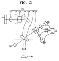
- an optical pick-up apparatus of the present invention includes a light source 100, an optical system 120, a front photo diode (FPD) 140, a diffraction element 160, and a photo diode integrated circuit (PDIC) 180.
- FPD front photo diode
- PDIC photo diode integrated circuit
- the light source 100 includes a first light source 100a for use with DVD (Digital Versatile Disc), and a second light source 100b for use with CD (Compact Disc).
- the light sources are laser diodes (LDs) that generate light beam having wavelength suitable for a particular media.
- the first light source 100a may emit light having a wavelength of 650nm for use with a DVD
- the second light source 100b may emit light having a wavelength of 780nm for use with a CD.
- the present exemplary embodiment illustrates two light sources which are suitable for use with CDs and DVDs
- additional light sources emitting a light having a wavelength such as 405nm for BDs (Blue-ray disc) and HD (High Definition) - DVDs can also be used.
- the optical system 120 includes a first beam splitter 122, a second beam splitter 124, a reflecting mirror 126, a collimating lens (CL) 128, a 1/4 (quarter) wavelength plate 130, an object lens (OL) 132, and a sensor lens (SL) 134.
- the first beam splitter 122 is a cubic beam splitter.
- the first beam splitter 122 reflects light emitted from the first light source 100a to change the optical path of that light, and transmits light emitted from the second light source 100b.
- This selective transmission is realized by utilizing the fact that the first and second light sources 100a, 100b emit light having different wavelengths from each other, or that the emitted lights have different polarization. Since beam splitting techniques are well known to those skilled in the art, further details are omitted for clarity and conciseness.
- the second beam splitter 124 reflects part of the light from the first beam splitter 122 towards the FPD 140, and reflect the remainder towards the reflecting mirror 126.
- the reflecting mirror 126 changes the path of the reflected light from the second beam splitter 124 to guide the light so that it is incident on the object lens 132.
- the CL 128 collimates the reflected light from the reflecting mirror 126.
- the quarter wavelength plate 130 changes linearly polarized light transmitted by the CL 128 into circularly polarized light, and changes circularly polarized light reflected from the disc to linearly polarized light.
- the function and operation of a quarter wavelength plate is also well-known to those skilled in the art, so further details are omitted for clarity and conciseness.
- the object lens 132 focuses the light emitted from the quarter wavelength plate 130 onto the disc.
- the sensor lens 134 consists of a concave lens, and magnifies the spot of a reflected light from the disc to form an effective (focal) spot by means of the PDIC 180.
- the sensor lens 134 is also able to generate astigmatism of the reflected light from the disc to produce an FE signal.
- the FPD 140 receives part of the light emitted from the first and second light sources 100a, 100b, and measures the intensity of the emitted light. The result is provided to a controller (not shown) for controlling voltages to the first and second light sources 100a, 100b. In this manner, it is possible to control the intensity of the emitted light to maintain the intensity at a substantially constant level.
- the diffraction element 160 includes a first diffraction element 160a for diffracting a light beam emitted from the first light source 100a, and a second diffraction element 160b for diffracting a light beam emitted from the second light source 100b. Since the first and the second diffraction element 160a, 160b are identical in their functions and configurations, a detailed description will only be provided for one of them.
- the diffraction element 160 is divided into three areas, a first, a second and a third area 162, 164, 166.
- the second area 164 is located between the first area 162 and the third area 166, and each area is composed of a diffraction grating having a constant period.
- the diffraction gratings of the first area 162 and the third area 166 are formed along the radial direction of the disc, so the diffraction element 160 forms a plurality of diffracted beams on one single track of the disc.
- the diffraction gratings of the first area 162 and the third area 166 are dislocated by 1/2 pitch (P/2) from each other.
- a 180 degree phase difference is generated at the portion diffracted by the first and third areas 162, 166 of the sub-beams SB1, SB2 which are the ⁇ 1 st order diffracted beams.
- the diffraction gratings of the first and third areas 162, 166 are offset by 180 degrees from each other.
- the diffraction grating of the second area 164 is formed substantially perpendicularly to the diffraction gratings of the first and third areas 162, 166. That is, the diffraction grating of the second area 164 is formed in the tangential direction of the disc.
- a light beam emitted from the light source 100 is diffracted and split into one main beam MB and three sub-beams SB1, SB2, SB3.
- the diffraction element 160 does not generate any phase difference in the main beam MB. Namely, the main beam MB has the same phase as the incident light on the diffraction element 160.
- the first and second sub-beams SB1, SB2 are diffracted in the tangential direction with respect of the main beam MB, whereas the third sub-beam SB3 is diffracted in the radial direction with respect to the main beam MB.
- the first and second sub-beams SB1, SB2 are further split into two beams (SB1b, SB1c) (SB2b, SB2c), respectively, each being diffracted by the first area 162 and the third area 166 of the diffraction element 160.
- the two beams in each pair (SB1b, SB1c) (SB2b, SB2c) have a 180 degree phase difference, respectively. That is to say, if one of beams SB1b, SB2b has a -90 degree phase difference with respect to the main beam MB, the other beam SB1c, SB2c has a +90 degree phase difference with respect to the main beam MB.
- the third sub-beam SB3 is diffracted by the diffraction grating of the second area of the diffraction element 160, and split into two beams SB3a, SB3b that are formed in the radial direction of the disc.
- the main beam MB and the three sub-beams SB1, SB2, SB3, each being split by the diffraction element 160 go through the first beam splitter 122, the second beam splitter 124, the reflecting mirror 126, the collimating lens 128, the quarter wavelength plate 130, and the object lens 132 in sequence (please refer to FIG. 3 ), and are irradiated onto a track of the disc. Then, the beams MB, SB1, SB2, SB3 are reflected and diffracted by the disc, and go through the object lens 132, the quarter wavelength plate 130, the collimating lens 128, the reflecting mirror 126, the second beam splitter 124, and the sensor lens 134 in sequence (please refer to FIG. 3 ) before they are finally irradiated onto the PDIC 180.
- the PDIC 180 is an element that converts a reflected beam from the disc into an electrical signal, and detects an RF (Radio Frequency) signal, an FE signal and a TE signal.
- RF Radio Frequency
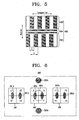
- the PDIC 180 includes three photodetecting elements 182, 184, 186.
- the photodetecting element 182 installed at the center is for use with the main beam, and is divided into four areas A, B, C and D.
- the photodetecting elements 184, 186 on both sides of the photodetecting element 182 are for use with the first and second sub-beams, and each is divided into four areas E1, E2, E3 and E4, and F1, F2, F3 and F4, respectively.
- These areas (A, B, C and D), (E1, E2, E3 and E4), and (F1, F2, F3 and F4) receive the main beam MB and the sub-beams SB1, SB2, and output detected electrical signals representing the intensities of the received beams.
- the RF signal, the FE signal and the TE signal are calculated from these electrical signals. For instance, the FE signal is obtained by the differential astigmatic method, and the TE signal is obtained by the DPP method. More details on these methods are provided below.
- the electrical signals detected from the areas (A, B, C and D), (E1, E2, E3 and E4), (F1, F2, F3 and F4) are (a, b, c, d), (el, e2, e3, e4) and (f1, f2, f3, f4), respectively.
- the RF signal is generated by Equation 1
- the FE signal is generated by Equation 2
- the TE signal is generated by Equation 3.
- the first and second sub-beams SB1, SB2 are diffracted from the disc and split into two beams (SB1b, SB1c) and (SB2b, SB2c), respectively. These beams are irradiated onto the first photodetecting element 184 and the second photodetecting element 186 for use with sub-beams, respectively.
- a beam diffracted by the second area (164 in FIG. 4 ) is deleted and the rest is received by the first and second photodetecting elements 184, 186.
- the third beam SB3 diffracted from the diffraction element 160 is received by none of the photodetecting elements 182, 184, 186 since the first and second photodetecting elements for use with sub-beams 184, 186 are arranged in the tangential direction of the disc. That is, the third beam SB3 is not required to calculate the FE and TE signals.
- preferred embodiments of the present invention can be advantageously used for keeping the TE signal value constant even though the light beam emitted from the light source is not irradiated onto the center of the diffraction element due to an assembly error in the diffraction element or other optical elements. Therefore, irrespective of assembly error, a normal TE signal can be calculated.
Landscapes
- Physics & Mathematics (AREA)
- Optics & Photonics (AREA)
- General Physics & Mathematics (AREA)
- Optical Recording Or Reproduction (AREA)
- Optical Head (AREA)
- Diffracting Gratings Or Hologram Optical Elements (AREA)
Claims (7)
- Beugungselement (160) zur Verwendung in einem optischen Abtastgerät, mit:einem ersten Beugungsgittergebiet (162) mit einer ersten vorbestimmten Periode;einem zweiten Beugungsgittergebiet (164) mit einer zweiten vorbestimmten Periode; undeinem dritten Beugungsgittergebiet (166) mit einer dritten vorbestimmten Periode,wobei das Beugungsgitter des ersten Gebiets im Wesentlich zum Beugungsgitter des dritten Gebiets parallel liegt und das Beugungsgitter des zweiten Gebiets im Wesentlichen senkrecht zu den Beugungsgittern des ersten Gebiets und des dritten Gebiets liegt, dadurch gekennzeichnet, dass
die erste und die dritte vorbestimmte Periode die gleiche vorbestimmte Periode sind, und
die Beugungsgitter des ersten Gebiets (162) und des dritten Gebiets (166) voneinander um 180 Grad versetzt angeordnet sind. - Beugungselement (160) nach Anspruch 1, wobei
die Beugungsgitter des ersten Gebiets (162) und des dritten Gebiets (166) entlang der radialen Richtung eines optischen Aufzeichnungsmediums (D) ausgebildet sind. - Beugungselement nach einem der vorhergehenden Ansprüche, wobei
das Beugungsgitter des zweiten Gebiets (164) entlang der tangentialen Richtung eines optischen Aufzeichnungsmediums (D) ausgebildet ist. - Optisches Abtastgerät, mit:einer Lichtquelle (100);einem Beugungselement (160) nach einem der Ansprüche 1 bis 3;einem optischen System (124, 126, 128, 130, 132) zum Strahlen der von dem Beugungselement gebeugten Strahlen auf ein optisches Aufzeichnungsmedium (D) und Führen des vom optischen Aufzeichnungsmedium reflektierten Lichts; undeinem integrierten Photodiodenschaltkreis (PDIC)(180) zum Empfangen von von dem optischen System geführtem Licht und Detektieren eines HF-Signals, eines FE-Signals und eines TE-Signals.
- Optisches Abtastgerät nach Anspruch 4, wobei
die Beugungsgitter des ersten und des dritten Gebiets (162, 166) entlang der radialen Richtung eines optischen Aufzeichnungsmediums (D) ausgebildet sind. - Optisches Abtastgerät nach Anspruch 5, wobei
die Lichtquelle (100) eine erste Lichtquelle (100a) für eine DVD und eine zweite Lichtquelle (100b) für eine CD umfasst, und
das Beugungselement (166) ein erstes (160a) und ein zweites (160b) Beugungselement zur Beugung von von der ersten bzw. zweiten Lichtquelle abgegebenem Licht umfasst. - Optisches Abtastgerät nach Anspruch 6, wobei das optische System (124, 126, 128, 130, 132) Folgendes umfasst:einen ersten Strahlteiler (122) zum Ändern des Lichtwegs des von der ersten Lichtquelle (100a) abgegebenen Lichts und Senden des von der zweiten Lichtquelle (100b) abgegebenen Lichts;einen zweiten Strahlteiler (124) zum Ändern des Lichtwegs des von dem ersten Strahlteiler abgegebenen Lichts und Führen des von dem optischen Aufzeichnungsmedium in Richtung des PDIC (180) reflektierten Lichts;eine Kollimierlinse (128) zum Kollimieren des von dem zweiten Strahlteiler abgegebenen Lichts; undeine optische Objektivlinse (132) zum Fokussieren des Lichts von der Kollimierlinse auf das optische Aufzeichnungsmedium (D).
Applications Claiming Priority (1)
| Application Number | Priority Date | Filing Date | Title |
|---|---|---|---|
| KR1020050005474A KR100754517B1 (ko) | 2005-01-20 | 2005-01-20 | 회절소자 및 이를 포함하는 광픽업장치 |
Publications (3)
| Publication Number | Publication Date |
|---|---|
| EP1684274A2 EP1684274A2 (de) | 2006-07-26 |
| EP1684274A3 EP1684274A3 (de) | 2006-09-20 |
| EP1684274B1 true EP1684274B1 (de) | 2009-03-04 |
Family
ID=36202455
Family Applications (1)
| Application Number | Title | Priority Date | Filing Date |
|---|---|---|---|
| EP05257982A Expired - Lifetime EP1684274B1 (de) | 2005-01-20 | 2005-12-22 | Diffraktionselement und optische Lesekopfvorrichtung damit |
Country Status (5)
| Country | Link |
|---|---|
| US (1) | US7609607B2 (de) |
| EP (1) | EP1684274B1 (de) |
| KR (1) | KR100754517B1 (de) |
| CN (1) | CN100395827C (de) |
| DE (1) | DE602005013054D1 (de) |
Families Citing this family (14)
| Publication number | Priority date | Publication date | Assignee | Title |
|---|---|---|---|---|
| US7245407B2 (en) * | 2002-06-10 | 2007-07-17 | Matsushita Electric Industrial Co., Ltd. | Complex objective lens compatible with information media of different thicknesses |
| KR100765393B1 (ko) * | 2005-07-11 | 2007-10-10 | 엘지전자 주식회사 | 부빔의 각도 조정이 필요없는 광 디스크 장치의 광 픽업 |
| CN101140772B (zh) * | 2006-09-07 | 2012-10-10 | 松下电器产业株式会社 | 光学头和光盘装置 |
| WO2008041330A1 (en) * | 2006-10-04 | 2008-04-10 | Pioneer Corporation | Pickup device |
| JP2009223937A (ja) | 2008-03-14 | 2009-10-01 | Ricoh Co Ltd | 光ピックアップおよびこれを用いる光情報処理装置 |
| JP2009223936A (ja) * | 2008-03-14 | 2009-10-01 | Ricoh Co Ltd | 光ピックアップおよびこれを用いる光情報処理装置 |
| JP5178339B2 (ja) * | 2008-06-20 | 2013-04-10 | 三洋電機株式会社 | 光ピックアップ装置 |
| JP5142879B2 (ja) * | 2008-08-06 | 2013-02-13 | 株式会社日立メディアエレクトロニクス | 光ピックアップおよび光ディスク装置 |
| JP5433533B2 (ja) * | 2010-09-03 | 2014-03-05 | 株式会社日立メディアエレクトロニクス | 光ピックアップ装置および光ディスク装置 |
| CN102736152A (zh) * | 2011-04-13 | 2012-10-17 | 中国科学院微电子研究所 | 一种偶次级透射光栅 |
| US11867556B2 (en) | 2015-07-29 | 2024-01-09 | Samsung Electronics Co., Ltd. | Spectrometer including metasurface |
| US10514296B2 (en) | 2015-07-29 | 2019-12-24 | Samsung Electronics Co., Ltd. | Spectrometer including metasurface |
| US11268854B2 (en) | 2015-07-29 | 2022-03-08 | Samsung Electronics Co., Ltd. | Spectrometer including metasurface |
| CN108603839A (zh) * | 2016-04-18 | 2018-09-28 | 惠普发展公司,有限责任合伙企业 | 散射辐射的多重光谱的同时检测 |
Family Cites Families (21)
| Publication number | Priority date | Publication date | Assignee | Title |
|---|---|---|---|---|
| JPH0675300B2 (ja) | 1988-04-11 | 1994-09-21 | 三菱電機株式会社 | 光学式ヘッド装置 |
| US5066138A (en) * | 1988-06-16 | 1991-11-19 | Mitsubishi Denki Kabushiki Kaisha | Optical head apparatus |
| JPH0227534A (ja) | 1988-07-16 | 1990-01-30 | Mitsubishi Electric Corp | 光学式ヘッド装置 |
| DE68923833T2 (de) * | 1988-06-20 | 1996-06-13 | Mitsubishi Electric Corp | Optischer Kopf mit Kippkorrekturservomechanismus. |
| US4983017A (en) * | 1988-08-02 | 1991-01-08 | Sharp Kabushiki Kaisha | Optical head device for reading information stored in a recording medium |
| JPH083910B2 (ja) | 1989-01-13 | 1996-01-17 | シャープ株式会社 | 光ピックアップ装置 |
| US5835471A (en) * | 1995-06-12 | 1998-11-10 | Canon Kabushiki Kaisha | Optical information recording and/or reproducing apparatus |
| JP3549301B2 (ja) * | 1995-09-08 | 2004-08-04 | 三菱電機株式会社 | 光ヘッドのトラッキング誤差検出装置 |
| JP3606961B2 (ja) | 1995-09-25 | 2005-01-05 | シャープ株式会社 | 光ピックアップ装置 |
| JP3661694B2 (ja) * | 1998-02-16 | 2005-06-15 | 株式会社日立製作所 | 光ヘッドおよび光ディスク装置 |
| JP3371846B2 (ja) | 1999-04-06 | 2003-01-27 | 日本電気株式会社 | ホログラム素子 |
| JP2001014717A (ja) * | 1999-04-28 | 2001-01-19 | Matsushita Electronics Industry Corp | 光学装置 |
| WO2002021520A1 (en) * | 2000-09-06 | 2002-03-14 | Hitachi, Ltd. | Optical head and optical disk device |
| JP2003091856A (ja) * | 2001-09-18 | 2003-03-28 | Sony Corp | 光学ピックアップ |
| JP3834810B2 (ja) * | 2001-09-19 | 2006-10-18 | 日本電気株式会社 | 光ヘッド装置 |
| WO2003075267A1 (en) * | 2002-03-06 | 2003-09-12 | Matsushita Electric Industrial Co., Ltd. | Optical head device and optical information device using this, and computer, optical disk player, car navigation system, optical disy recorder and optical disk server using this optical information device |
| JP2004091856A (ja) | 2002-08-30 | 2004-03-25 | Sumitomo Metal Ind Ltd | 酸洗鋼板の製造方法及び酸洗装置 |
| JP3799318B2 (ja) | 2002-10-22 | 2006-07-19 | 株式会社日立製作所 | 光ピックアップおよびそれを用いた光学的情報記録装置または再生装置 |
| JP2004327005A (ja) | 2003-04-11 | 2004-11-18 | Sankyo Seiki Mfg Co Ltd | 光ヘッド装置、回折素子、および回折素子の製造方法 |
| JP2004334962A (ja) * | 2003-05-06 | 2004-11-25 | Sony Corp | 光ヘッド及び光記録媒体記録再生装置 |
| TWI325078B (en) * | 2003-10-15 | 2010-05-21 | Hon Hai Prec Ind Co Ltd | Planar light device and liquid crystal display |
-
2005
- 2005-01-20 KR KR1020050005474A patent/KR100754517B1/ko not_active Expired - Fee Related
- 2005-10-21 US US11/254,697 patent/US7609607B2/en not_active Expired - Fee Related
- 2005-11-25 CN CNB2005101150806A patent/CN100395827C/zh not_active Expired - Fee Related
- 2005-12-22 EP EP05257982A patent/EP1684274B1/de not_active Expired - Lifetime
- 2005-12-22 DE DE602005013054T patent/DE602005013054D1/de not_active Expired - Lifetime
Also Published As
| Publication number | Publication date |
|---|---|
| EP1684274A3 (de) | 2006-09-20 |
| CN1808576A (zh) | 2006-07-26 |
| EP1684274A2 (de) | 2006-07-26 |
| KR20060084689A (ko) | 2006-07-25 |
| DE602005013054D1 (de) | 2009-04-16 |
| US20060158996A1 (en) | 2006-07-20 |
| KR100754517B1 (ko) | 2007-09-03 |
| US7609607B2 (en) | 2009-10-27 |
| CN100395827C (zh) | 2008-06-18 |
Similar Documents
| Publication | Publication Date | Title |
|---|---|---|
| US6392977B2 (en) | Optical pickup with a hologram to limit the aperture of two light beams with different wavelengths | |
| EP1684274B1 (de) | Diffraktionselement und optische Lesekopfvorrichtung damit | |
| US7136344B2 (en) | Optical head device and optical information recording/reproducing apparatus | |
| US20020196726A1 (en) | Optical pickup device | |
| KR100624852B1 (ko) | 광학 유닛 | |
| US7643395B2 (en) | Diffraction element and optical pick-up apparatus having the same | |
| EP1600958B1 (de) | Optische Abtastkopfeinheit keine Phasenkorrektur benötigend | |
| CN1323390C (zh) | 光学头、光盘驱动器和光学系统调整方法 | |
| KR20080017807A (ko) | 광픽업 | |
| US7075879B2 (en) | Optical pickup device and a method to control an angle between a pit and a major axis of a laser beam | |
| CN100424760C (zh) | 衍射元件和具有该衍射元件的光学拾取设备 | |
| US20060120248A1 (en) | Diffraction element and optical pick-up apparatus having the same | |
| KR100624853B1 (ko) | 광학 유닛 | |
| KR100463424B1 (ko) | 광 픽업장치의 광검출기 | |
| KR100565797B1 (ko) | 멀티 기록/재생용 광픽업장치 | |
| KR100692574B1 (ko) | 회절소자 및 이를 포함하는 광픽업장치 | |
| US20060262708A1 (en) | Optical head unit and optical disc apparatus | |
| JP2005310298A (ja) | 光ピックアップおよび光情報処理装置 | |
| US20060158995A1 (en) | Optical pickup device and focusing control method of the same | |
| JP2004171786A (ja) | 光学ヘッド装置及びディスクドライブ装置 | |
| JP2006338826A (ja) | 光学装置と光ピックアップ装置および光学ディスク装置 | |
| KR20110080706A (ko) | 회절 격자 및 이를 채용한 광 픽업 | |
| JP2009146505A (ja) | 光ピックアップ装置 |
Legal Events
| Date | Code | Title | Description |
|---|---|---|---|
| PUAI | Public reference made under article 153(3) epc to a published international application that has entered the european phase |
Free format text: ORIGINAL CODE: 0009012 |
|
| AK | Designated contracting states |
Kind code of ref document: A2 Designated state(s): AT BE BG CH CY CZ DE DK EE ES FI FR GB GR HU IE IS IT LI LT LU LV MC NL PL PT RO SE SI SK TR |
|
| AX | Request for extension of the european patent |
Extension state: AL BA HR MK YU |
|
| PUAL | Search report despatched |
Free format text: ORIGINAL CODE: 0009013 |
|
| AK | Designated contracting states |
Kind code of ref document: A3 Designated state(s): AT BE BG CH CY CZ DE DK EE ES FI FR GB GR HU IE IS IT LI LT LU LV MC NL PL PT RO SE SI SK TR |
|
| AX | Request for extension of the european patent |
Extension state: AL BA HR MK YU |
|
| 17P | Request for examination filed |
Effective date: 20061019 |
|
| 17Q | First examination report despatched |
Effective date: 20061218 |
|
| AKX | Designation fees paid |
Designated state(s): DE GB NL |
|
| GRAP | Despatch of communication of intention to grant a patent |
Free format text: ORIGINAL CODE: EPIDOSNIGR1 |
|
| GRAS | Grant fee paid |
Free format text: ORIGINAL CODE: EPIDOSNIGR3 |
|
| GRAA | (expected) grant |
Free format text: ORIGINAL CODE: 0009210 |
|
| AK | Designated contracting states |
Kind code of ref document: B1 Designated state(s): DE GB NL |
|
| REG | Reference to a national code |
Ref country code: GB Ref legal event code: FG4D |
|
| REF | Corresponds to: |
Ref document number: 602005013054 Country of ref document: DE Date of ref document: 20090416 Kind code of ref document: P |
|
| PLBE | No opposition filed within time limit |
Free format text: ORIGINAL CODE: 0009261 |
|
| STAA | Information on the status of an ep patent application or granted ep patent |
Free format text: STATUS: NO OPPOSITION FILED WITHIN TIME LIMIT |
|
| 26N | No opposition filed |
Effective date: 20091207 |
|
| PGFP | Annual fee paid to national office [announced via postgrant information from national office to epo] |
Ref country code: NL Payment date: 20171121 Year of fee payment: 13 Ref country code: DE Payment date: 20171121 Year of fee payment: 13 |
|
| PGFP | Annual fee paid to national office [announced via postgrant information from national office to epo] |
Ref country code: GB Payment date: 20171121 Year of fee payment: 13 |
|
| REG | Reference to a national code |
Ref country code: DE Ref legal event code: R119 Ref document number: 602005013054 Country of ref document: DE |
|
| REG | Reference to a national code |
Ref country code: NL Ref legal event code: MM Effective date: 20190101 |
|
| GBPC | Gb: european patent ceased through non-payment of renewal fee |
Effective date: 20181222 |
|
| PG25 | Lapsed in a contracting state [announced via postgrant information from national office to epo] |
Ref country code: NL Free format text: LAPSE BECAUSE OF NON-PAYMENT OF DUE FEES Effective date: 20190101 |
|
| PG25 | Lapsed in a contracting state [announced via postgrant information from national office to epo] |
Ref country code: DE Free format text: LAPSE BECAUSE OF NON-PAYMENT OF DUE FEES Effective date: 20190702 |
|
| PG25 | Lapsed in a contracting state [announced via postgrant information from national office to epo] |
Ref country code: GB Free format text: LAPSE BECAUSE OF NON-PAYMENT OF DUE FEES Effective date: 20181222 |