EP1600958B1 - Optische Abtastkopfeinheit keine Phasenkorrektur benötigend - Google Patents
Optische Abtastkopfeinheit keine Phasenkorrektur benötigend Download PDFInfo
- Publication number
- EP1600958B1 EP1600958B1 EP05251051A EP05251051A EP1600958B1 EP 1600958 B1 EP1600958 B1 EP 1600958B1 EP 05251051 A EP05251051 A EP 05251051A EP 05251051 A EP05251051 A EP 05251051A EP 1600958 B1 EP1600958 B1 EP 1600958B1
- Authority
- EP
- European Patent Office
- Prior art keywords
- optical
- diffraction grating
- pickup unit
- optical pickup
- disc
- Prior art date
- Legal status (The legal status is an assumption and is not a legal conclusion. Google has not performed a legal analysis and makes no representation as to the accuracy of the status listed.)
- Expired - Fee Related
Links
- 230000003287 optical effect Effects 0.000 title claims description 175
- 239000011295 pitch Substances 0.000 claims description 16
- 238000000034 method Methods 0.000 description 29
- 201000009310 astigmatism Diseases 0.000 description 5
- 239000004065 semiconductor Substances 0.000 description 2
Images


Classifications
-
- G—PHYSICS
- G11—INFORMATION STORAGE
- G11B—INFORMATION STORAGE BASED ON RELATIVE MOVEMENT BETWEEN RECORD CARRIER AND TRANSDUCER
- G11B7/00—Recording or reproducing by optical means, e.g. recording using a thermal beam of optical radiation by modifying optical properties or the physical structure, reproducing using an optical beam at lower power by sensing optical properties; Record carriers therefor
- G11B7/12—Heads, e.g. forming of the optical beam spot or modulation of the optical beam
- G11B7/135—Means for guiding the beam from the source to the record carrier or from the record carrier to the detector
- G11B7/1353—Diffractive elements, e.g. holograms or gratings
-
- G—PHYSICS
- G11—INFORMATION STORAGE
- G11B—INFORMATION STORAGE BASED ON RELATIVE MOVEMENT BETWEEN RECORD CARRIER AND TRANSDUCER
- G11B7/00—Recording or reproducing by optical means, e.g. recording using a thermal beam of optical radiation by modifying optical properties or the physical structure, reproducing using an optical beam at lower power by sensing optical properties; Record carriers therefor
- G11B7/12—Heads, e.g. forming of the optical beam spot or modulation of the optical beam
- G11B7/135—Means for guiding the beam from the source to the record carrier or from the record carrier to the detector
- G11B7/1398—Means for shaping the cross-section of the beam, e.g. into circular or elliptical cross-section
-
- G—PHYSICS
- G11—INFORMATION STORAGE
- G11B—INFORMATION STORAGE BASED ON RELATIVE MOVEMENT BETWEEN RECORD CARRIER AND TRANSDUCER
- G11B7/00—Recording or reproducing by optical means, e.g. recording using a thermal beam of optical radiation by modifying optical properties or the physical structure, reproducing using an optical beam at lower power by sensing optical properties; Record carriers therefor
- G11B2007/0003—Recording, reproducing or erasing systems characterised by the structure or type of the carrier
- G11B2007/0006—Recording, reproducing or erasing systems characterised by the structure or type of the carrier adapted for scanning different types of carrier, e.g. CD & DVD
-
- G—PHYSICS
- G11—INFORMATION STORAGE
- G11B—INFORMATION STORAGE BASED ON RELATIVE MOVEMENT BETWEEN RECORD CARRIER AND TRANSDUCER
- G11B7/00—Recording or reproducing by optical means, e.g. recording using a thermal beam of optical radiation by modifying optical properties or the physical structure, reproducing using an optical beam at lower power by sensing optical properties; Record carriers therefor
- G11B7/08—Disposition or mounting of heads or light sources relatively to record carriers
- G11B7/09—Disposition or mounting of heads or light sources relatively to record carriers with provision for moving the light beam or focus plane for the purpose of maintaining alignment of the light beam relative to the record carrier during transducing operation, e.g. to compensate for surface irregularities of the latter or for track following
- G11B7/0901—Disposition or mounting of heads or light sources relatively to record carriers with provision for moving the light beam or focus plane for the purpose of maintaining alignment of the light beam relative to the record carrier during transducing operation, e.g. to compensate for surface irregularities of the latter or for track following for track following only
- G11B7/0903—Multi-beam tracking systems
Definitions
- This invention relates to an optical pickup unit for recording/reproducing data in/from an optical recording medium (an optical disc) and, in particular, to improvement of the optical pickup unit which adopts a DPP method as a tracking servo method.
- the optical pickup unit is a unit for recording/reproducing data in/from the optical disc.
- optical discs DVDs (digital versatile discs or digital video discs), CDs (compact discs), and so on.
- CDs compact discs
- CD-R compact disc-recordable
- CD-RW CD-rewritable
- the CD-R is a writable CD which can record only one time.
- the CD-RW is a rewritable CD using a phase-change recording system.
- DVDs DVD-R (DVD Recordable), DVD-RAM, DVD+RW (DVD+Rewritable), DVD-RW (DEV Rewritable), and so on.
- DVD-R is a writable DVD which can record only one time.
- the DVD-RAM is a rewritable version of the DVD.
- the optical pickup unit of the type described it is necessary for the optical pickup unit of the type described to irradiate a laser beam produced by an optical source on a predetermined track of the optical disc.
- tracking servo methods using three beams are used up to now.
- the tracking servo methods using three beams are classified into two kinds of methods: a three beam method and a DPP (differential push-pull) method according to difference between methods of generating a tracking error signal.
- Both of the three beam method and the DPP method divide the laser beam produced by the optical source by a diffraction grating into three beams which consists of a zero-order diffracted beam and a pair of first-order diffracted beams.
- the zero-order diffracted beam is called a main beam while the pair of first-order diffracted beams are called sub beams.
- the pair of first-order diffracted beams one crossing the track first is called a leading sub beam while another crossing the track later is called a trailing sub beam.
- the leading sub beam is called a first sub beam while the trailing sub beam is called a second sub beam.
- the leading sub beam and the trailing sub beam are disposed so that a phase difference therebetween becomes 180 degrees in terms of a phase of a track crossing signal.
- a track error signal is generated by subtracting a signal (a received signal of a photo-detector) due to a spot of the trailing sub beam from another signal (another received signal of the photo-detector) due to another spot of the leading sub beam.
- a recorded medium an optical disc.
- Such a three beam method is used in a case of reproducing a CD (compact disc).
- a push-pull signal due to a spot of the leading sub beam is called a leading sub push-pull signal
- a push-pull signal due to a spot of the trailing sub beam is called a trailing sub push-pull signal
- a push-pull signal due to a spot of the main beam is called a main push-pull signal.
- a tracking error signal is generated by subtracting an added signal obtained by adding the leading sub push-pull signal and the trailing sub push-pull signal from the main push-pull signal.
- it is necessary to dispose the leading sub beam and the trailing sub beam so that a phase difference therebetween becomes 360 degrees in terms of a phase of the track crossing signal.
- the DPP method it is possible to remain only a push-pull signal as the tracking error signal by subtracting the added signal obtained by adding the leading sub push-pull signal and the trailing sub push-pull signal from the main push-pull signal.
- the DPP method is advantageous in that it is possible to cancel a offset component of the push-pull signal caused by a tilt of the optical disc and a shift of an objective lens.
- a particular optical pickup unit is mounted in order to enable to record/reproduce data in/from both of the DVD and the CD.
- the particular optical pickup unit of the type is for carrying out recording or reproducing by selectively using two kinds of laser beams, namely, a laser beam having a short wavelength (wavelength band of 650 nm) for the DVD and a laser beam having a long wavelength (wavelength band of 780 nm).
- the particular optical pickup unit is called a two-wavelength handling optical pickup unit.
- Such a two-wavelength handling optical pickup unit is disclosed in Japanese Unexamined Patent Application Publication No. 2001-195767 or JP-A 2001-195767 .
- a track pitch is different between the CD and the DVD. Accordingly, in a conventional optical pickup unit, it is necessary to adjust a phase between the leading sub beam and the trailing sub beam by rotating a diffraction grating around an optical axis in accordance with the type of the optical disc.
- the conventional pickup unit which adopts the DPP method as the tracking servo method, it is necessary to adjust the phase by mounting the diffraction grating operating at various wavelengths in accordance with the type of the optical discs in order to obtain a stable tracking error signal for the optical discs having different track pitches.
- the conventional optical pickup unit it is necessary for the conventional optical pickup unit to make a phase adjustment so that the phase difference between the leading sub beam (the first sub beam) and the trailing sub beam (the second sub beam) becomes 360 degrees in terms of the phase of the track crossing signal.
- the above-mentioned phase adjustment must be carried out in accordance with the type of the optical discs in order to obtain the stable tracking error signal (DPP signal) for the optical discs having the different track pitches.
- a diffraction grating for separating an incident beam from an optical source into a main beam and first and second sub beams, wherein each of said first and said second sub beams has, in use, on an optical disc, an elliptic spot shape which becomes longer in a radial direction of the optical disc and which, in use, spans at least two tracks, the diffraction grating being characterized by having at least one curved pattern where a plurality of curved grooves having the same radius are equidistantly placed.
- the diffraction grating may have a repetition pattern so that a partial curved pattern is repeated plural times in a predetermined direction.
- the partial curved pattern has a plurality of curved grooves having the same shape which are equidistantly placed.
- an optical disc and an optical pickup unit comprising a diffraction grating as described above.
- the optical pickup unit may be an optical pickup unit which enables to record or reproduce to first and second optical discs.
- the first and the second optical disc have track pitches and using wavelengths both of which are different to each other.
- the optical pickup unit comprises a photodetector for detecting a return beam reflected by each of the first and the second optical discs.
- the photodetector may comprise a quadripartite photodiode for receiving the main beam, a first tripartite photodiode for receiving the first sub beam, and a second tripartite photodiode for receiving the second sub beam.
- Fig. 1 is a view showing an optical system of the conventional optical pickup unit.
- the illustrated optical pickup unit comprises a semiconductor laser (laser diode) LD as an optical source, a diffraction grating GRT, a collimator lens CL, a half mirror HM, an objective lens OL, a converging lens (sensor lens) SL, and a photodetector (light receiving element) DET.
- a reference symbol of DISC designates an optical disc.
- the laser diode LD radiates a laser beam having a predetermined wavelength.
- the diffraction grating GRT separates the outgoing laser beam from the laser diode LD into three laser beams.
- a center beam or a zero-order diffracted beam is called a main beam while two both side beams or a pair of first-order diffracted beams are called sub beams (a leading sub beam and a trailing sub beam).
- the collimator lens CL collimates the three laser beams from the diffraction grating GRT into a collimated beam.
- the half mirror HM transmits the collimated beam from the collimator lens CL and reflects a return beam (a reflected beam from the optical disc DISC) which will later be described.
- the objective lens OL converges the laser beam transmitted through the half mirror HM on an information recording face of the optical disc DISC. Reflected by the optical disc DISC, the reflected beam is incident to the half mirror HM as the return beam. Reflected by the half mirror HM, the return beam is converged and subjected astigmatism by the converging lens SL and is delivered to the photodetector DET which generates an electric signal in accordance with an optical strength thereof.
- the laser beam Radiated by the laser diode LD, the laser beam is separated into the three laser beams by the diffraction grating GRT, is converted into the collimated beam by the collimator lens CL, and is incident to the half mirror HM.
- the half mirror HM transmits the incident collimated beam.
- the transmitted beam is converged by the objective lens OL and is irradiated on the information recording face of the optical disc DISC.
- the optical disc DISC reflects the irradiated beam in accordance with information (pits) formed on the information recording face. Reflected by the information recording face, the reflected beam transmits the objective lens OL and is incident to the half mirror HM as the return beam. The incident return beam is reflected by the half mirror HM, is converged and subjected astigmatism by the converging lens SL, and is detected by the photodetector DET. The photodetector DET converts the detected beam into the electric signal.
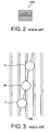
- Fig. 2 shows a conventional diffraction grating GRT for use in the conventional optical pickup unit illustrated in Fig. 1 .
- the conventional diffraction grating GRT has a GRT pattern where a plurality of linear grooves are equidistantly placed.
- Fig. 3 shows a state of spots where the leaser beam radiated by the conventional optical pickup unit comprising the conventional diffraction grating GRT is converged and irradiated on the information recording face of the optical disc DISC.
- the conventional optical pickup unit comprising the conventional diffraction grating GRT
- a plurality of tracks TR are formed on the information recording face of the optical disc DISC.
- An interval between adjacent tracks TR is called a track pitch.
- leading sub beam L and the trailing sub beam T are symmetrically placed with respect to the main beam M with a space left in a direction along the track TR and in a direction normal to the track TR.
- the leading sub beam L and the trailing sub beam T are arranged so that a phase difference therebetween becomes 360 degrees in terms of a phase of a track crossing signal.
- each of the main beam M, the leading sub beam L, and the trailing sub beam T has a circular spot shape on the information recording face of the optical disc DISC.
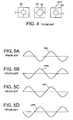
- Fig. 4 shows structure of the photodetector DET for use in the conventional optical pickup unit illustrated in Fig. 1 and shapes of the return beam.
- the illustrated photodetector DET comprises a quadripartite photodiode 31 for receiving the main beam M, a first bipartite photodiode 32 for receiving the leading sub beam L, and a second bipartite photodiode 33 for receiving the trailing sub beam T.
- the photodetector DET illustrated in Fig. 4 shows structure in a case where a focus error signal is generated by using a known astigmatism method using the main beam M.
- the return beam of the main beam M, the leading sub beam L, and the trailing sub beam T has a circular shape.
- Figs. 5A, 5B, 5C, and 5D show a leading push-pull signal PPL, a main push-pull signal PPM, a trailing push-pull signal PPT, and a tracking error signal DPP, respectively.
- the leading push-pull signal PPL, the main push-pull signal PPM, and the trailing push-pull signal are received by the photodetector DET illustrated in Fig. 4 .
- the tracking error signal DPP is generated by adding and subtracting their push-pull signals PPL, PPM, and PPT.
- the tracking error signal DPP is obtained by multiplying the constant K by a signal obtained by adding the leading push-pull signal PPL and the trailing push-pull signal PPT and by subtracting a multiplied signal from the main push-pull signal PPM.
- the conventional pickup unit which adopts the DPP method as the tracking servo method, it is necessary to adjust the phase by mounting the diffraction grating operating at various wavelengths in accordance with the type of the optical discs in order to obtain a stable tracking error signal DDP for the optical discs having different track pitches.
- the conventional optical pickup unit it is necessary for the conventional optical pickup unit to make a phase adjustment so that the phase difference between the leading sub beam (the first sub beam) L and the trailing sub beam (the second sub beam) T becomes 360 degrees in terms of the phase of the track crossing signal.
- the above-mentioned phase adjustment must be carried out in accordance with the type of the optical discs in order to obtain the stable tracking error signal DPP for the optical discs having the different track pitches, as mentioned in the preamble of the instant specification.
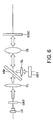
- FIG. 6 is a system structure view of an optical system of the optical pickup unit.
- the illustrated optical pickup unit is similar in structure and operation to the conventional optical pickup unit illustrated in Fig. 1 except that the diffraction grating is different from that illustrated in Fig. 1 as will later become clear.
- the diffraction grating is therefore depicted at GRT'.
- the same reference symbols are attached to components similar to those illustrated in Fig. 1 and their description will be omitted for purposes of simplification of the description.
- Fig. 7 shows structure of the diffraction grating GRT' for use in the optical pickup unit illustrated in Fig. 6 .
- the diffraction grating GRT' has an arc pattern where a plurality of arc grooves are equidistantly placed. It is noted that the arc grooves have the same radius but are not concentric circles.
- the diffraction grating GRT' may have a hyperbolic pattern where a plurality of hyperbolic grooves are equidistantly placed or a parabolic pattern where a plurality of parabolic grooves are equidistantly placed in lieu of the arc pattern.
- the diffraction grating GRT' may have a curved pattern where a plurality of curved grooves having the same shape are equidistantly placed.
- Fig. 8 shows a state of spots where the laser beam radiated by the optical pickup unit according to this invention comprising the diffraction grating GRT' illustrated in Fig. 7 is converged and irradiated on the information recording face of the optical disc DISC.
- a leading sub beam L' and a trailing sub beam T' are symmetrically placed with respect to the main beam M with a space left in a direction along the track TR.
- the main beam M has a circular spot shape on the information recording face of the optical disc DISC while each of the leading sub beam L' and the trailing sub beam T' has, on the information recording face of the optical disc DISC, an elliptic spot shape which becomes longer in a radial direction of the optical disc DISC and which spans a plurality of tracks.
- the elliptic spot in each of the leading sub beam L' and the trailing sub beam T' spans three tracks, the elliptic spot may span at least two tracks.
- Fig. 9 shows structure of the photodetector DET for use in the optical pickup unit illustrated in Fig. 6 and shapes of the return beam.
- the illustrated photodetector DET has similar in structure to the photodetector DET illustrated in Fig. 4 .
- the photodetector DET illustrated in Fig. 9 shows structure in a case where a focus error signal is generated by using a known astigmatism method using the main beam M.
- the return beam of the main beam M has a circular shape while the return beam of each of the leading sub beam L and the trailing sub beam T has an elliptic shape.
- Figs. 10A, 10B, 10C, and 10D show a leading push-pull signal PPL, a main push-pull signal PPM, a trailing push-pull signal PPT, and a tracking error signal DPP, respectively.
- the leading push-pull signal PPL, the main push-pull signal PPM, and the trailing push-pull signal are received by the photodetector DET illustrated in Fig. 9 .
- the tracking error signal DPP is generated by adding and subtracting their push-pull signals PPL, PPM, and PPT.
- the tracking error signal DPP is obtained by multiplying the constant K by a signal obtained by adding the leading push-pull signal PPL and the trailing push-pull signal PPT and by subtracting a multiplied signal from the main push-pull signal PPM.
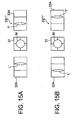
- Fig. 11 shows a region of the laser beam where the objective lens OL uses in the diffraction grating GRT' according to an embodiment of this invention.
- Fig. 12 shows states of spots of the laser beam on the information recording face of the optical disc DISC where the laser beam is converged and irradiated through the objective lens OL in the optical pickup unit comprising the diffraction grating GRT' illustrated in Fig. 11 .
- the objective lens OL enables to shift leftward and rightward with respect to an optical base for tracking control.
- the region of the laser beam used by the diffraction grating GRT' shifts between a right-hand region R(R) and a left-hand region R(L) through a middle region R(M), as shown in Fig. 11 .
- a middle view shows a state of spots of the laser beam on the information recording face of the optical disc DISC when the objective lens OL does not shift
- a right-hand view shows a state of spots of the laser beam on the information recording face of the optical disc DISC when the objective lens OL shifts the rightward
- a left-hand view shows a state of spots of the laser beam on the information recording face of the optical disc DISC when the objective lens OL shifts the leftward.
- the leading sub beam L' and the trailing sub beam T' are symmetrically placed around the main beam M although the objective lens OL shifts the leftward or the rightward.
- the leading sub beam L' and the trailing sub beam T' rotates in a counterclockwise around the main beam M.
- the leading sub beam L' and the trailing sub beam T' rotates in a clockwise around the main beam M.
- the used region of the laser beam in the diffraction grating GRT' becomes the right-hand region R(R) or the left-hand region R(L) in the diffraction grating GRT' and only uses a part of curvatures in the arc grooves formed in the diffraction grating GRT', as shown in Fig. 11 .
- the leading sub beam L' and the trailing sub beam T' rotate counterclockwise or clockwise around the main beam M.
- each of the leading sub beam L' and the trailing sub beam T' has the elliptic spot shape so as to span at least two tracks TR of the optical disk DISC although the objective lens OL shift rightward or leftward.
- Fig. 13 shows a diffraction grating GRT" according to another embodiment of this invention and a region of the laser beam where the objective lens OL uses in the diffraction grating GRT".
- Fig. 14 shows states of spots of the laser beam on the information recording face of the optical disc DISC where the laser beam is converged and irradiated through the objective lens OL in the optical pickup unit comprising the diffraction grating GRT" illustrated in Fig. 13 .
- the illustrated diffraction grating GRT" has a repetition pattern wherein a plurality of partial arc patterns are symmetrically placed about a center line CL with a lateral direction.
- Each partial arc pattern has a plurality of arc grooves having the same radius which are equidistantly placed.
- the repetition pattern in the diffraction grating GRT" is a pattern so that the partial arc pattern is repeated four times in the lateral direction.
- the diffraction grating GRT" may have a repetition pattern so that a partial curved pattern is repeated plural times in a predetermined direction.
- the partial curved pattern has a plurality of curved grooves having the same shape which are equidistantly placed.
- the partial curved pattern may be a partial hyperbolic pattern having a plurality of hyperbolic grooves which are equidistantly placed or a partial parabolic pattern having a plurality of parabolic grooves are equidistantly placed.
- a middle view shows a state of spots of the laser beam on the information recording face of the optical disc DISC when the objective lens OL does not shift
- a right-hand view shows a state of spots of the laser beam on the information recording face of the optical disc DISC when the objective lens OL shifts the rightward
- a left-hand view shows a state of spots of the laser beam on the information recording face of the optical disc DISC when the objective lens OL shifts the leftward.
- the leading sub beam L' and the trailing sub beam T' are symmetrically placed around the main beam M although the objective lens OL shifts the leftward or the rightward.
- the leading sub beam L' and the trailing sub beam T' rotates in a counterclockwise around the main beam M.
- the leading sub beam L' and the trailing sub beam T' rotates in a clockwise around the main beam M.
- a used region of the laser beam in the diffraction grating GRT" uses all of curvatures of the arc grooves formed in the diffraction grating GRT", as shown in Fig. 13 .
- the leading sub beam L" and the trailing sub beam T" are always symmetrically placed around the main beam M along the track direction although the objective lens OL shifts leftward or rightward, as shown in Fig. 14 .
- the two-wavelength handling optical pickup unit is a unit to enable to record/reproduce data in/from first and second optical discs having a different track pitch.
- the first optical disc may be a DVD and the second optical disc may be a CD.
- the two-wavelength handling optical pickup unit is similar in structure to the optical pickup unit illustrated in Fig. 6 except for points which will presently be described.
- the two-wavelength handling optical pickup unit uses a two-wavelength laser (not shown) in place of the laser diode LD and comprises an optical axis correction element between the diffraction grating and the two-wavelength laser and a photodetector which is modified from that illustrated in Fig. 9 as will later become clear.
- the two-wavelength laser comprises a semiconductor chip wherein first and second laser diodes are integrated.
- the first laser diode radiates a first laser beam having a wavelength band of 650 nm for the DVD while the second laser diode radiates a second laser beam having a wavelength band of 780 nm for the CD.
- the first and the second laser diodes are left with a mutual distance (a distance between emission points) which is, for example, about 110 ⁇ m.
- the first and the second laser diodes can be manufactured in a distance precision of ⁇ 1 ⁇ m.
- the optical axis correction element makes optical axes of the first and the second laser beams coincide to deliver the laser beam to the diffraction grating GRT'.
- Figs. 15A and 15B show structure of the photodetector DET' for use in the two-wavelength handling optical pickup unit according to this invention and shapes of the return beam.
- Fig. 15A shows a received beam pattern in the photodetector DET' when the optical disc is the DVD.
- Fig. 15B shows a received beam pattern in the photodetector DET' when the optical disc is the CD.
- the illustrated photodetector DET' comprises the quadripartite photodiode 31 for receiving the main beam M, a first tripartite photodiode 32A for receiving the leading sub beam L', and a second tripartite photodiode 33A for receiving the trailing sub beam T'.
- the photodetector DET' illustrated in Figs. 15A and 15B shows structure in a case where a focus error signal is generated by using a known astigmatism method using the main beam M.
- the tripartite photodiode is used as a photodiode for receiving the sub beam, it is possible to easily constitute the photodetector DET' suitable for the two-wavelength handling optical pickup unit.
- the two-wavelength handling optical pickup unit having such structure, no rotation adjustment of the diffraction grating GRT' is required in the manner which is similar to a case of the optical pickup unit described with reference to Figs. 6 through 9 .
- the stable tracking error signal DPP for the optical discs having the different track pitch.
- this invention has thus far been described in conjunction with a few preferred embodiments thereof, it will now be readily possible for those skilled in the art to put this invention into various other manners. That is, although the above-mentioned embodiments describe about cases where this invention is applied to a one-wavelength handling optical pickup unit and the two-wavelength handling optical pickup unit, this invention may be applicable to optical pickup units which enable to hand with three or more wavelengths. In addition, this invention may be applicable to an optical pickup unit which enables to deal with two or more types of optical discs having different track pitch and using the same wavelength such as a DVD-RAM which has a track pitch different from those of a DVD-R, a DVD-RW, and a DVD+RW.
- a DVD-RAM which has a track pitch different from those of a DVD-R, a DVD-RW, and a DVD+RW.
- the two-wavelength handling optical pickup unit comprises the two-wavelength laser as the optical source
- the two-wavelength handling optical unit may comprise a first laser diode for radiating a first laser beam and a second laser diode for radiating a second laser beam, independently.
- a beam splitter may be used as the optical axis correction element.
- the diffraction gratings are not restricted to those illustrated in Figs. 7 , 11 , and 13 . At any rate, the diffraction grating may has any structure so that each of the first and the second sub beams on the optical disc has an ellipse spot shape which becomes longer in a radial direction of the optical disc and which spans at least two tracks.
Landscapes
- Physics & Mathematics (AREA)
- Optics & Photonics (AREA)
- Optical Head (AREA)
- Optical Recording Or Reproduction (AREA)
Claims (4)
- Beugungsgitter (GRT'; GRT") zum Trennen eines einfallenden Strahls von einer optischen Quelle (LD) in einen Hauptstrahl (M) und erste und zweite Nebenstrahlen (L', T; L", T"), wobei jeder der ersten und zweiten Nebenstrahlen im Gebrauch auf einer optischen Platte (DISC) eine elliptische Fleckform aufweist, die in einer radialen Richtung der optischen Platte länger wird und die im Gebrauch wenigstens zwei Spuren (TR) überspannt, wobei das Beugungsgitter dadurch gekennzeichnet ist, dass es wenigstens ein Bogenmuster aufweist, das aus einer Vielzahl von bogenförmigen Rillen besteht, die den gleichen Radius aufweisen, wobei das Zentrum der bogenförmigen Rillen entlang einer bestimmten Richtung des Gitters äquidistant angeordnet ist.
- Beugungsgitter (GRT'; GRT") zum Trennen eines einfallenden Strahls von einer optischen Quelle (LD) in einen Hauptstrahl (M) und erste und zweite Nebenstrahlen (L', T"; L", T"), wobei jeder der ersten und zweiten Nebenstrahlen im Gebrauch auf einer optischen Platte (DISC) eine elliptische Fleckform aufweist, die in einer radialen Richtung der optischen Platte länger wird und die im Gebrauch wenigstens zwei Spuren (TR) überspannt, wobei das Beugungsgitter dadurch gekennzeichnet ist, dass das Beugungsgitter (GRT") ein Wiederholungsmuster derart aufweist, dass ein bogenförmiges Teilmuster mehrmals in einer bestimmten Richtung wiederholt wird, wobei das bogenförmige Teilmuster aus einer Vielzahl von bogenförmigen Rillen besteht, die den gleichen Radius aufweisen, wobei das Zentrum der bogenförmigen Rillen entlang einer bestimmten Richtung des Gitters äquidistant angeordnet ist.
- Kombination aus einer optischen Platte und einer optischen Lesekopfeinheit, die ein Beugungsgitter nach einem der vorherigen Ansprüche umfasst.
- Kombination aus einer optischen Platte und einer optischen Lesekopfeinheit nach Anspruch 3, wobei die optische Lesekopfeinheit eine Multiwellenlängen-Verarbeitungseinheit, die in der Lage ist, im Gebrauch auf eine erste und zweite optische Platte aufzuzeichnen oder zu kopieren, die unterschiedliche Spurabstände aufweisen, wobei die optische Lesekopfeinheit darüber hinaus einen Photodetektor zum Erfassen eines Rückstrahls umfasst, der jeweils von der ersten oder zweiten optischen Platte reflektiert wird, wobei der Photodetektor (DET') eine vierteilige Photodiode (31) zum Empfangen des Hauptstrahl (M), eine erste dreiteilige Photodiode (32A) zum Empfangen des ersten Nebenstrahls (L') und eine zweite dreiteilige Photodiode (33A) zum Empfangen des zweiten Nebenstrahls (T') umfasst.
Applications Claiming Priority (2)
| Application Number | Priority Date | Filing Date | Title |
|---|---|---|---|
| JP2004155563 | 2004-05-26 | ||
| JP2004155563A JP2005339646A (ja) | 2004-05-26 | 2004-05-26 | 光ピックアップおよびそれに使用される回折格子 |
Publications (3)
| Publication Number | Publication Date |
|---|---|
| EP1600958A2 EP1600958A2 (de) | 2005-11-30 |
| EP1600958A3 EP1600958A3 (de) | 2007-06-13 |
| EP1600958B1 true EP1600958B1 (de) | 2009-06-10 |
Family
ID=34940505
Family Applications (1)
| Application Number | Title | Priority Date | Filing Date |
|---|---|---|---|
| EP05251051A Expired - Fee Related EP1600958B1 (de) | 2004-05-26 | 2005-02-23 | Optische Abtastkopfeinheit keine Phasenkorrektur benötigend |
Country Status (5)
| Country | Link |
|---|---|
| US (1) | US20050265203A1 (de) |
| EP (1) | EP1600958B1 (de) |
| JP (1) | JP2005339646A (de) |
| CN (1) | CN100472622C (de) |
| DE (1) | DE602005014827D1 (de) |
Families Citing this family (8)
| Publication number | Priority date | Publication date | Assignee | Title |
|---|---|---|---|---|
| EP1736975A1 (de) * | 2005-06-16 | 2006-12-27 | Deutsche Thomson-Brandt Gmbh | Abtastgerät für ein optisches Aufzeichnungsmedium |
| JP2007080466A (ja) * | 2005-09-16 | 2007-03-29 | Toshiba Corp | 光ヘッド装置及び光ディスク装置 |
| JP2007299495A (ja) * | 2006-05-02 | 2007-11-15 | Sony Corp | 光ピックアップ装置及び情報処理装置 |
| JP2008090935A (ja) * | 2006-10-02 | 2008-04-17 | Mitsumi Electric Co Ltd | 光検出器及びそれを用いた光ピックアップ |
| CN101339779B (zh) * | 2008-07-09 | 2011-11-02 | 中国华录·松下电子信息有限公司 | 光盘视盘机的循迹伺服方法及专用装置 |
| CN102043242B (zh) * | 2009-10-26 | 2012-07-11 | 致伸科技股份有限公司 | 激光扫描读取器 |
| JP2012119047A (ja) * | 2010-11-09 | 2012-06-21 | Panasonic Corp | 光ピックアップおよび当該光ピックアップを備える光ディスク装置 |
| US20140091198A1 (en) * | 2011-10-11 | 2014-04-03 | Mitsubishi Electric Corporation | Laser output measurement mechanism |
Family Cites Families (11)
| Publication number | Priority date | Publication date | Assignee | Title |
|---|---|---|---|---|
| EP0305169B1 (de) * | 1987-08-24 | 1994-05-11 | Sharp Kabushiki Kaisha | Optische Abtastvorrichtung und optische Gitteranordnung dazu |
| US5066138A (en) * | 1988-06-16 | 1991-11-19 | Mitsubishi Denki Kabushiki Kaisha | Optical head apparatus |
| EP0588385B1 (de) * | 1989-02-13 | 1997-10-15 | Omron Corporation | Datenaufzeichnungs-/Wiedergabevorrichtung für optische Karte |
| JP2865223B2 (ja) * | 1990-12-28 | 1999-03-08 | 松下電子工業株式会社 | 光ピックアップ用偏光板および光ピックアップ装置 |
| EP0621590B1 (de) * | 1993-04-23 | 2000-03-29 | Canon Kabushiki Kaisha | Optisches Informationsaufzeichnungs- und/oder Wiedergabegerät |
| JP3530735B2 (ja) * | 1998-01-29 | 2004-05-24 | パイオニア株式会社 | 光学式情報再生装置 |
| US6738326B1 (en) * | 1999-07-07 | 2004-05-18 | Matsushita Electric Industrial Co., Ltd. | Apparatus and method for reproducing information from two types of optical disks having discrimination marks formed along tracks thereof |
| US6567355B2 (en) * | 1999-12-03 | 2003-05-20 | Hitachi, Ltd. | Optical detector, optical pickup and optical information reproducing apparatus using optical pickup |
| CN1213411C (zh) * | 2000-03-07 | 2005-08-03 | Tdk株式会社 | 光盘头、激光二极管模块和光学录/放装置 |
| US6873589B2 (en) * | 2000-10-20 | 2005-03-29 | Sony Corporation | Method and device for detecting optical data and reading-writing apparatus for optical data |
| JP2003233918A (ja) * | 2002-02-08 | 2003-08-22 | Fujitsu Ltd | 光情報処理装置 |
-
2004
- 2004-05-26 JP JP2004155563A patent/JP2005339646A/ja active Pending
-
2005
- 2005-01-28 CN CNB2005100051199A patent/CN100472622C/zh not_active Expired - Fee Related
- 2005-02-23 DE DE602005014827T patent/DE602005014827D1/de not_active Expired - Lifetime
- 2005-02-23 EP EP05251051A patent/EP1600958B1/de not_active Expired - Fee Related
- 2005-02-24 US US11/067,448 patent/US20050265203A1/en not_active Abandoned
Also Published As
| Publication number | Publication date |
|---|---|
| US20050265203A1 (en) | 2005-12-01 |
| EP1600958A2 (de) | 2005-11-30 |
| CN100472622C (zh) | 2009-03-25 |
| CN1702747A (zh) | 2005-11-30 |
| DE602005014827D1 (de) | 2009-07-23 |
| EP1600958A3 (de) | 2007-06-13 |
| JP2005339646A (ja) | 2005-12-08 |
Similar Documents
| Publication | Publication Date | Title |
|---|---|---|
| KR100315637B1 (ko) | 씨디-알더블유의 재생/기록이 가능한 디브이디-롬 광학계 | |
| US7362689B2 (en) | Optical pickup and optical recording and/or reproducing apparatus adopting the same | |
| JPH11134702A (ja) | 光ピックアップ装置 | |
| EP1684274B1 (de) | Diffraktionselement und optische Lesekopfvorrichtung damit | |
| US7283440B2 (en) | Tracking error signal detecting method selectively using a push-pull method, an improved push-pull method, and a three beam method and optical recording/reproducing apparatus using the same | |
| EP1600958B1 (de) | Optische Abtastkopfeinheit keine Phasenkorrektur benötigend | |
| US7800988B2 (en) | Optical recording using secondary tracking method | |
| KR20060047831A (ko) | 광픽업 및 광학 기록 매체 기록 및/또는 재생 장치 | |
| JP3666860B2 (ja) | 光ピックアップ装置 | |
| KR100756042B1 (ko) | 회절소자 및 이를 포함하는 광픽업장치 | |
| EP1665243B1 (de) | Fotodioden-ic | |
| KR100717017B1 (ko) | 광픽업 및 이를 채용한 광 기록 및/또는 재생기기 | |
| JP2006004499A (ja) | 光ピックアップ装置および光ディスク装置 | |
| KR100565036B1 (ko) | 호환형 광픽업장치 | |
| US7881168B2 (en) | Optical pick-up apparatus for multi recording/reproducing | |
| JP2004334962A (ja) | 光ヘッド及び光記録媒体記録再生装置 | |
| CN100424760C (zh) | 衍射元件和具有该衍射元件的光学拾取设备 | |
| KR100370205B1 (ko) | 호환형 광픽업장치 | |
| US6956192B2 (en) | Optical head and optical disk drive | |
| KR100463424B1 (ko) | 광 픽업장치의 광검출기 | |
| KR20010029131A (ko) | 광픽업장치 | |
| JPH09245356A (ja) | 光学ヘッドおよび光記録装置 | |
| JP5102698B2 (ja) | 光ピックアップ装置および光ディスク装置 | |
| KR20010047945A (ko) | 호환형 광픽업장치 | |
| JP2005108279A (ja) | 光学ヘッドおよび光ディスク装置 |
Legal Events
| Date | Code | Title | Description |
|---|---|---|---|
| PUAI | Public reference made under article 153(3) epc to a published international application that has entered the european phase |
Free format text: ORIGINAL CODE: 0009012 |
|
| AK | Designated contracting states |
Kind code of ref document: A2 Designated state(s): AT BE BG CH CY CZ DE DK EE ES FI FR GB GR HU IE IS IT LI LT LU MC NL PL PT RO SE SI SK TR |
|
| AX | Request for extension of the european patent |
Extension state: AL BA HR LV MK YU |
|
| PUAL | Search report despatched |
Free format text: ORIGINAL CODE: 0009013 |
|
| AK | Designated contracting states |
Kind code of ref document: A3 Designated state(s): AT BE BG CH CY CZ DE DK EE ES FI FR GB GR HU IE IS IT LI LT LU MC NL PL PT RO SE SI SK TR |
|
| AX | Request for extension of the european patent |
Extension state: AL BA HR LV MK YU |
|
| RIC1 | Information provided on ipc code assigned before grant |
Ipc: G11B 7/135 20060101AFI20070508BHEP |
|
| 17P | Request for examination filed |
Effective date: 20071203 |
|
| 17Q | First examination report despatched |
Effective date: 20080122 |
|
| AKX | Designation fees paid |
Designated state(s): DE FR NL |
|
| GRAC | Information related to communication of intention to grant a patent modified |
Free format text: ORIGINAL CODE: EPIDOSCIGR1 |
|
| GRAP | Despatch of communication of intention to grant a patent |
Free format text: ORIGINAL CODE: EPIDOSNIGR1 |
|
| GRAS | Grant fee paid |
Free format text: ORIGINAL CODE: EPIDOSNIGR3 |
|
| GRAA | (expected) grant |
Free format text: ORIGINAL CODE: 0009210 |
|
| AK | Designated contracting states |
Kind code of ref document: B1 Designated state(s): DE FR NL |
|
| REF | Corresponds to: |
Ref document number: 602005014827 Country of ref document: DE Date of ref document: 20090723 Kind code of ref document: P |
|
| PLBE | No opposition filed within time limit |
Free format text: ORIGINAL CODE: 0009261 |
|
| STAA | Information on the status of an ep patent application or granted ep patent |
Free format text: STATUS: NO OPPOSITION FILED WITHIN TIME LIMIT |
|
| 26N | No opposition filed |
Effective date: 20100311 |
|
| PGFP | Annual fee paid to national office [announced via postgrant information from national office to epo] |
Ref country code: FR Payment date: 20100223 Year of fee payment: 6 |
|
| PGFP | Annual fee paid to national office [announced via postgrant information from national office to epo] |
Ref country code: DE Payment date: 20100303 Year of fee payment: 6 |
|
| REG | Reference to a national code |
Ref country code: NL Ref legal event code: V1 Effective date: 20100901 |
|
| PG25 | Lapsed in a contracting state [announced via postgrant information from national office to epo] |
Ref country code: NL Free format text: LAPSE BECAUSE OF NON-PAYMENT OF DUE FEES Effective date: 20100901 |
|
| REG | Reference to a national code |
Ref country code: FR Ref legal event code: ST Effective date: 20111102 |
|
| REG | Reference to a national code |
Ref country code: DE Ref legal event code: R119 Ref document number: 602005014827 Country of ref document: DE Effective date: 20110901 |
|
| PG25 | Lapsed in a contracting state [announced via postgrant information from national office to epo] |
Ref country code: FR Free format text: LAPSE BECAUSE OF NON-PAYMENT OF DUE FEES Effective date: 20110228 |
|
| PG25 | Lapsed in a contracting state [announced via postgrant information from national office to epo] |
Ref country code: DE Free format text: LAPSE BECAUSE OF NON-PAYMENT OF DUE FEES Effective date: 20110901 |