EP1683403B1 - Stromversorgung mit verbesserter kühlung - Google Patents
Stromversorgung mit verbesserter kühlung Download PDFInfo
- Publication number
- EP1683403B1 EP1683403B1 EP03818987A EP03818987A EP1683403B1 EP 1683403 B1 EP1683403 B1 EP 1683403B1 EP 03818987 A EP03818987 A EP 03818987A EP 03818987 A EP03818987 A EP 03818987A EP 1683403 B1 EP1683403 B1 EP 1683403B1
- Authority
- EP
- European Patent Office
- Prior art keywords
- wall portion
- casing
- air duct
- cover
- side plate
- Prior art date
- Legal status (The legal status is an assumption and is not a legal conclusion. Google has not performed a legal analysis and makes no representation as to the accuracy of the status listed.)
- Expired - Lifetime
Links
- 238000001816 cooling Methods 0.000 title description 10
- 239000004411 aluminium Substances 0.000 claims description 9
- 229910052782 aluminium Inorganic materials 0.000 claims description 9
- XAGFODPZIPBFFR-UHFFFAOYSA-N aluminium Chemical compound [Al] XAGFODPZIPBFFR-UHFFFAOYSA-N 0.000 claims description 9
- 239000004065 semiconductor Substances 0.000 claims description 6
- 229910052751 metal Inorganic materials 0.000 claims description 4
- 239000002184 metal Substances 0.000 claims description 4
- 239000002918 waste heat Substances 0.000 abstract description 9
- LAXBNTIAOJWAOP-UHFFFAOYSA-N 2-chlorobiphenyl Chemical compound ClC1=CC=CC=C1C1=CC=CC=C1 LAXBNTIAOJWAOP-UHFFFAOYSA-N 0.000 description 11
- 101710149812 Pyruvate carboxylase 1 Proteins 0.000 description 11
- 230000001965 increasing effect Effects 0.000 description 5
- 125000006850 spacer group Chemical group 0.000 description 5
- 238000004519 manufacturing process Methods 0.000 description 3
- 230000017525 heat dissipation Effects 0.000 description 2
- 239000000463 material Substances 0.000 description 2
- 150000002739 metals Chemical class 0.000 description 2
- 238000000034 method Methods 0.000 description 2
- 238000005476 soldering Methods 0.000 description 2
- 238000009423 ventilation Methods 0.000 description 2
- RYGMFSIKBFXOCR-UHFFFAOYSA-N Copper Chemical compound [Cu] RYGMFSIKBFXOCR-UHFFFAOYSA-N 0.000 description 1
- 238000004026 adhesive bonding Methods 0.000 description 1
- 238000005452 bending Methods 0.000 description 1
- 239000004020 conductor Substances 0.000 description 1
- 229910052802 copper Inorganic materials 0.000 description 1
- 239000010949 copper Substances 0.000 description 1
- 230000005484 gravity Effects 0.000 description 1
- 230000001939 inductive effect Effects 0.000 description 1
- 229920002994 synthetic fiber Polymers 0.000 description 1
- 239000004753 textile Substances 0.000 description 1
- 238000003466 welding Methods 0.000 description 1
Images


Classifications
-
- H—ELECTRICITY
- H05—ELECTRIC TECHNIQUES NOT OTHERWISE PROVIDED FOR
- H05K—PRINTED CIRCUITS; CASINGS OR CONSTRUCTIONAL DETAILS OF ELECTRIC APPARATUS; MANUFACTURE OF ASSEMBLAGES OF ELECTRICAL COMPONENTS
- H05K7/00—Constructional details common to different types of electric apparatus
- H05K7/20—Modifications to facilitate cooling, ventilating, or heating
- H05K7/2089—Modifications to facilitate cooling, ventilating, or heating for power electronics, e.g. for inverters for controlling motor
- H05K7/20909—Forced ventilation, e.g. on heat dissipaters coupled to components
- H05K7/20918—Forced ventilation, e.g. on heat dissipaters coupled to components the components being isolated from air flow, e.g. hollow heat sinks, wind tunnels or funnels
Definitions
- the invention relates to an electrical and/or electronical device, particularly a power supply, including a casing, an electric and/or electronic circuit with a heat generating component and at least one fan, where the heat generating component is in thermal contact with a wall portion of the casing.
- Document US 4,699,208 A discloses an electronic circuit of a textile machine.
- the device includes a housing with a bended air duct running from a front wall to a side wall of the housing.
- a heat sink including a plate with cooling ribs is positioned in the air duct such that the plate replaces a part of the wall portion of the air duct.
- a thyristor module of an electronic circuit is shown in direct contact with the plate of the heat sink such that the heat generated by the thyristor module is transferred to the ribbed body 17. The heat is dissipated by the air flow through the air duct produced by a blower.
- the electrical and/or electronical device for example a power supply, an amplifier or the like, includes a casing and an electric and/or electronic circuit.
- the casing includes a double wall portion with an inner wall portion that is a part of the inner surface of the casing and an outer wall portion that is a part of the outer surface of the casing.
- the double wall portion defines an air duct between the inner wall portion and the outer wall portion.
- the power supply further includes a fan that is arranged such that the air flow produced by the fan, or at least a part of it, is directed through the air duct.
- the circuit includes a plurality of components such as mechanical, electric and/or electronic components.
- the circuit includes one or more heat generating components such as for example an inductive element of a transformer or power semiconductors.
- the heat generating component is arranged within the casing such that it is in thermal contact with the inner wall portion of the double wall portion of the casing. Therefore, said double wall portion acts as a heat sink for the heat produced by the heat generating component. The heat then is emitted from the casing to the surrounding air and also to the air duct from where it is dissipated by the air flow from the fan.
- the heat generating component does not have to be in direct physical contact with the inner wall portion.
- the thermal contact between the heat generating component and the inner wall portion of the casing could also be established via a heat conducting adapter, such as for example an aluminium block, an aluminium angle plate, a heat-pipe or any other suitable heat conductor.
- a very efficient heat dissipation can be achieved. Since the heat generating components are in good thermal contact with the casing of the power supply, the heat generated by the power supply can be effectively transferred to the casing. Furthermore, by providing an air duct within the casing, the surface for transferring the heat from the casing to the surrounding air can be increased. And finally, the fan produces a high air flow through the air duct that efficiently dissipates the heat from the air duct.
- Another advantage is that the space requirements are low.
- the air duct in the double wall portion can be provided very space-efficiently.
- the additional costs for providing a double wall portion of the casing are significantly smaller than for providing an supplementary traditional heat sink.
- the invention enables very flexible designs because the shape and the dimensions of the air duct can be varied very easily and in a wide range.
- the cross sectional area or the shape of the cross section of the air duct can be varied.
- the air duct can have a closed cross section such as for example a rectangular, a circular or an oval cross section. In this case, all of the air transits the air duct.
- the air duct may also have holes where some of the air may escape from the air duct.
- the air duct can also have an open cross section such as for example a C-like or a U-like cross section. In this case, some of the air that enters the air duct, leaves the air duct through the open side of it and does not transit entirely through it.
- the casing is enough stable and sturdy, it could be made of any suitable material such as for example any synthetic material or metals. But in order to enhance the heat transfer from the heat generating component to the casing and further to the air, the casing is preferably made of a material with a high coefficient of thermal conductivity such as for example metals like copper or aluminium. The usage of aluminium is favoured because of its lower specific gravity and the lower manufacturing costs.
- the electric and/or electronic circuit can be realised in any known manner.
- printed cirucit boards are commonly used and are therefore preferred to implement the circuit.
- the heat generating component is a part of the circuit, it is electrically connected to the printed circuit board in some way.
- the component is mounted directly on the surface of the board or the component includes wires that are soldered to the circuit board.
- the component may also be connected to the circuit board by a flexible connection such as cable.
- the shape of the casing is not critical for the realisation of the invention, almost any shape of the casing is possible. However, in order that a power supply according to the invention can be applied in many different applications, the appropriate standards should be observed. That is why the shape of the casing is preferably cubical with the dimensions corresponding to the relevant standards of the particular application.
- the casing can be of a one-piece or a multi-piece design.
- a one-piece design has the advantage that there is no need to assemble the casing, but it is more difficult to assemble the whole power supply, since most parts of the power supply are arranged within the casing.
- the casing includes multiple pieces, at least a bottom and a cover, where the printed circuit board is mounted on the bottom.
- the inner wall portion of the air duct is a part of the bottom and the outer wall portion of the air duct is a part of the cover.
- the bottom and the cover are fitted together so that a good thermal contact between them is accomplished and so that the inner wall portion and the outer wall portion are arranged to form the air duct. Since the power supply can be assembled at least partially before the bottom and the cover are fitted together, it is less laborious to manufacture the whole power supply.
- the casing may include further pieces, such as for example a separate front or rear panel.
- bottom and the cover there are many possibilities to assemble the bottom and the cover such as for example by means of rivets, nuts and bolts or screws and the like or by welding, soldering, bonding, gluing and the like.
- the bottom and the cover are screwed, because screwing is a simple, fast and cost-efficient method for assembling two pieces of metal.
- thermal paste can be applied between contacting parts of the bottom and the cover before they are fitted together.
- the bottom of the casing includes a base plate and a side plate which are arranged such that they are perpendicular to each other having a common edge.
- the side plate of the bottom is designated hereafter as the bottom side plate.
- the cover piece of the casing includes a top plate and a further side plate, hereafter designated as the cover side plate.
- the top plate and the cover side plate are also arranged perpendicular to each other and have a common edge.
- the cover side plate forms the outer wall portion of the casing's double wall portion.
- the printed circuit board is mounted on the bottom such that it is substantially parallel to the base plate and that one edge of the printed circuit board is in contact with the bottom side plate or is at least situated close to it.
- the heat generating component is mounted on the printed circuit board in the immediate vicinity of that edge such that the heat generating component is in contact with the bottom side plate or is positioned close to it. In order to have a good thermal contact the heat generating component can further be pressed against the bottom side plate by any suitable means such as for example bonding.
- the casing is of substantially cubical shape and the cover side plate forms the outer wall portion of the double wall portion.
- the cover side plate also forms an outer surface of the power supply's casing, particularly a lateral surface of the cubical casing. Therefore, the air duct is positioned along a lateral surface of the cubical casing. That is, the air duct leads from a front surface of the casing to the rear surface.
- the front surface includes at least one aperture where the air flow from the fan can enter the air duct.
- the rear surface of the caing also includes at least one aperture such that the air flow can escape from the air duct.
- the air flow through the air duct is always in the same direction, entering the air duct at an inlet, passing through it and quitting it at an outlet.
- the inlet is formed by the corresponding end regions of the bottom side plate and the cover side plate in the region of the front surface.
- the air flow through the air duct with straight end regions of these side plates may be sufficient for many applications. Other applications require increased cooling capabilities and therefore an increased air flow through the air duct.
- An increased air flow can be achieved by an inlet with a funnel-like shape.
- a simple and preferred way to realise a funnel-like shape of the inlet is bending the end region of the bottom side plate to an inner side of the casing.
- the fan that generates the air flow through the air duct is preferably arranged on the front surface of the cubical casing. It is arranged such that it covers the inlet of the air duct at least partially so that the air flow of the fan or a part of the air flow can directly enter the air duct.
- an additional heat sink is mounted within the air duct such that the air flow through the air duct also dissipates the heat from the additional heat sink.
- the additional heat sink is in good thermal contact with the double wall portion of the casing, that is either with one or more inner surfaces of the air duct. This ensures a good heat transfer from the casing to the additional heat sink.
- the invention can be applied in power supplies or other electrical and/or electronical devices where waste heat is generated.
- a preferred application of the invention are power supplies where the waste heat is generated by one or more power semiconductors, such as diodes, thyristors, transistors, triacs or other heat generating power semiconductors.
- the casing includes a second double wall portion with an inner wall portion and an outer wall portion that define a second air duct along the other surface of the casing.
- the air flow through the second air duct may be generated by the first fan or the power supply may include a second fan (or even further fans) to produce this second air flow. Since the second air duct acts as a second heat sink, more waste heat can be dissipated.
- the second double wall portion is preferably located along the second lateral surface of the casing and a second fan is arranged at the same surface as the first fan such that the air flow from the second fan is directed through the second air duct.
- FIG. 1 shows a schematic illustration of a cross section of a power supply 8 according to the invention.
- the power supply 8 includes a casing with a bottom 2 and a cover 3 that are made of aluminium sheets.
- the length of the power supply 8 is typically between 10 cm and 40 cm, the width between 4 cm and 25 cm and its height between 4 cm and 25 cm. While certain applications require thicker or thinner sheets, the thickness of the aluminium sheets varies typically between 0.5 mm and 3 mm.
- the bottom 2 includes a bottom plate 2.1 and two inner side plates 2.2 and the cover 3 includes a top plate 3.1 and two outer side plates 3.2.
- the bottom 2 is built such that it has a U-like shaped cross section, where the bottom plate 2.1 is the base of the U and the inner side plates 2.2 are the arms of the U.
- the cover 2 is also built such that it has a U-like shaped cross section, where the top plate 3.1 is the base of the U and the outer side plates 2.2 are the arms of the U.
- the cover 3 is wider than the bottom 2. They can therefore be assembled by inserting the bottom 2 into the cover 3 and fitted together by suitable means so as to achieve a good thermal conduction between the bottom 2 and the cover 3. They are for example screwed (not shown in fig. 1 ). When fitted together, the inner side plates 2.2 of the bottom 2 and the outer side plates 3.2 of the cover 3 define two air ducts 4.
- a printed circuit board PCB 1 is mounted on the bottom 2 such that it is substantially parallel to the bottom plate 2.1.
- Different components 6 are mounted on the PCB 1. These may be mechanical, electric, electronic or other components.
- the components can be positioned directly on the surface of the PCB 1 and soldered to corresponding soldering pads or they can be equipped with one or more wires that are soldered into corresponding holes in the PCB 1.
- the components can also be differently fitted to the PCB 1 as long as the necessary electrical and mechanical connections are established.
- heat generating components 5 are mounted. They are arranged such that they contact the inner side plates 2.2. Furthermore, they are tightly fitted to the inner side plates 2.2 so as to achieve a good thermal conduction between the heat generating components 5 and the inner side plates 2.2.
- the figures show a small gap between the bottom 2 and the cover 3 although they are tightly pressed together. The same applies to the illustration of the contact between the heat generating components 5 and the inner side plates 2.2.
- fig. 2 the same power supply 8 is shown as in fig. 1 .
- the only difference is that fig. 2 shows to fans 7, the positions of which are indicated with dashed lines.
- the fans 7 produce an air flow (not shown) that runs perpendicular to the drawing plane, partially through the inside of the casing and partially through the air ducts 4.
- the waste heat generated by the heat generating components 5 is efficiently transferred to the inner side plates 2.2, to the top plate 3.1 and the outer side plates 3.2.
- the waste heat can be efficiently spread over an enlarged surface area of the bottom 2 and the cover 3 both on the inside and on the outside of the casing. This means that the waste heat can be efficiently dissipated to the air within the casing, on the outside of the casing and within the air ducts 4.
- the air flow produced by the fans 7 efficiently dissipates the heated air within the casing as well as within the air ducts 4.
- Fig. 3 shows a cross section of the power supply 8 parallel to the bottom plate 2.1 in a top view.
- the PCB 1 with the heat generating components 5 can be seen as well as the inner side plates 2.2, the outer side plates 3.2 and the fans 7.
- the arrows 9 illustrate the air flow from the fans 7 and the arrows 9.1 designate the air flow through the air ducts 4.
- Fig. 4 shows a detailed view of the cross section of another power supply according to the invention.
- fig. 4 shows the inlet of an air duct 4.
- the inlet is formed by the front sections of the inner side plate 2.2 and the outer side plate 3.2.
- the front section 10 of the inner side plate 2.2 is bent towards the inside of the casing such that the inlet has a funnel-like shape. As a result, more air is blown through the air duct 4 by the fan 7 as shown by the arrows 9.1.
- FIG. 5 some schematic open cross sections of different implementations of the bottom 2 and the cover 3 to achieve good thermal conduction are illustrated. To simplify the drawings, neither the components 6 nor the heat generating components 5 are shown.
- the upper edge 2.3 of the inner side plate 2.2 is orthogonally angled to an inner side of the casing such that it is parallel to the top plate 3.1.
- a connection 11 for example a screw or a nut with corresponding bolt, that is positioned in the range of the angled upper edge 2.3, the bottom 2 and the cover 3 are fitted together such that the angled upper edge 2.3 is tightly pressed against the inner surface of the top plate 3.1.
- the upper edge 2.3 is orthogonally angled outwardly with respect to the casing of the power supply 8.
- the connection 11 corresponds to the connection 11 as shown in fig. 5a .
- the upper edge 2.3 is angled twice such that it has a U-shape.
- the screw or bolt of the connection 11 is arranged orthogonally to the inner side plate 2.2 and the outer side plate 3.2.
- the upper edge 2.3 of the inner side plate 2.2 is not angled but straight.
- a spacer 12 is inserted into the upper part of air duct 4.
- the connection 11 is arranged orthogonally to the inner side plate 2.2 and the outer side plate 3.2 right through the spacer 12.
- the spacer 12 also is made of aluminium.
- Fig. 5e shows an embodiment where the upper edge 2.3 of the inner side plate 2.2 is bent twice and has the shape of a Z such that its most upper part again is parallel to the outer side plate 3.2.
- fig. 5f it is not the inner side plate 2.2 that is bent but it is the corresponding portion 3.4 of the outer side plate 3.2 that is bent Z-like.
- FIG. 6 various embodiments of the power supply 8 are shown where the bottom 2 and the cover 3 define a closed or at least a partially closed air duct 4.
- the lower edge 3.3 of the outer side plate 3.2 or the corresponding lower portion 2.3 of the inner side plate 2.2 are built correspondingly.
- the lower edge 3.3 of the outer side plate 3.2 is bent Z-like and in fig. 6b it is bent U-like.
- the air duct 4 can also be closed by a spacer 12 that is inserted into the lower part of the air duct 4.
- the lower portion 2.4 of the inner side plate 2.2 is bent Z-like to realise the necessary distance between the inner side plate 2.2 and the outer side plate 3.2.
- a second connection 11 can be provided at the lower end of the air duct 4.
- the dimensions of the air duct 4 in a wide range by changing the shape of the bottom 2 and/or the cover 3.
- the dimensions and therewith also the cooling properties of the air duct 4 can be chosen such that the requirements of a particular application are met as good as possible.
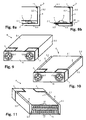
- FIG. 7 shows two examples how this could be done.
- a heat sink with a single base block 13 with two laterally extending fins 14 is shown.
- the connection 11 is positioned such that the base block 13, the inner side plate 2.2 and the outer site plate 3.2 are tightly pressed together. Thanks to the tight contact between the base block 13 and the inner side plate 2.2 as well as the outer site plate 3.2, the waste heat can be transferred to the fins 14 that are efficiently cooled by the high air flow trough the air duct 4.
- the additional heat sink includes a base block 13 at the upper end of the air duct 4 and a base block 13 at the lower end of it, both of them being connected by a fin 14.
- a base block 13 at the upper end of the air duct 4 and a base block 13 at the lower end of it, both of them being connected by a fin 14.
- Fig. 8a shows an embodiment where the heat generating component is mounted on the lower surface of the PCB 1 such that it is in thermal contact with the bottom plate 2.1 of the bottom 2.
- the outer side plate 3.2 is formed such that it includes a lower portion 3.5 that is parallel to the bottom plate 2.1 and covers that area of the bottom plate 2.1 where the heat generating component 5 is positioned.
- Fig. 8b shows a similar embodiment where the edge 3.3 of the lower portion 3.5 is bent Z-like to realise a closed air duct 4.
- the air duct 4 is separated into two single air ducts 4 by means of a spacer 12.
- the heat generating component 5 is mounted on the upper surface of the PCB 1. In this case, a good thermal conduction between the PCB 1 and the bottom plate 2.1 has to be ensured.
- the figures 9, 10 and 11 show an assembled power supply 8 according to the invention in a top view ( fig. 9 ), a bottom view ( fig. 10 ) and a back view ( fig. 11 ). Shown are the cover 3 with the top plate 3.1 and the outer side plates 3.2, the bottom 2 with the bottom plate 2.1 and the inner side plates 2.2, the fans 7 and the air ducts 4.
- figures 9 and 10 show a front panel 15 with suitable ventilation apertures 17 for the fans 7.
- the front panel 15 can be built separately or it can be a part of the bottom 2 or the cover 3.
- a rear panel 16 is shown in the back view of the power supply 8 in fig. 11 . It includes a plurality of ventilation apertures 17 as the outlets for the air that is directed through the casing.
- the rear panel includes connecting means such as plugs and the like (not shown) to connect the power supply 8 to the device that has to be supplied with power.
- the invention enables the manufacturing of electrical and/or electronical devices such as for example power supplies with highly improved cooling capabilities while only a minimum of extra space is required. Furthermore, the stability and sturdiness of the casing of the power supply can also be improved, since the bottom and the cover can be provided with additional contacting and fixation areas.
Landscapes
- Engineering & Computer Science (AREA)
- Microelectronics & Electronic Packaging (AREA)
- Physics & Mathematics (AREA)
- Thermal Sciences (AREA)
- Cooling Or The Like Of Electrical Apparatus (AREA)
- Cable Accessories (AREA)
- Non-Reversible Transmitting Devices (AREA)
Claims (11)
- Elektrische und/oder elektronische Vorrichtung (8), besonders eine Stromversorgung, mit einem Gehäuse, das im Wesentlichen quaderförmig ist, einer elektrischen und/oder elektronischen Schaltung (1) mit einer wärmeerzeugenden Komponente (5) und mindestens einem Gebläse (7), wobei die wärmeerzeugende Komponente mit einem Wandabschnitt des Gehäuses in thermischem Kontakt steht, dadurch gekennzeichnet, dass das Gehäuse einen Doppelwandabschnitt mit einem inneren Wandabschnitt (2.2) und einem äußeren Wandabschnitt (3.2) aufweist, wobei zwischen dem inneren Wandabschnitt und dem äußeren Wandabschnitt ein Luftkanal (4) definiert ist, wobei das Gehäuse einen Boden (2) und eine Abdeckung (3) aufweist, die in thermischem Kontakt aneinander angebracht sind, wobei der innere Wandabschnitt ein Teil des Bodens und der äußere Wandabschnitt ein Teil der Abdeckung ist, wobei die Schaltung auf einer Leiterplatte implementiert ist und die Leiterplatte auf dem Boden montiert ist, wobei die wärmeerzeugende Komponente mit dem inneren Wandabschnitt in thermischem Kontakt steht, wobei der Doppelwandabschnitt eine Wärmesenke ist und das mindestens eine Gebläse so angeordnet ist, dass eine durch das mindestens eine Gebläse erzeugte Luftströmung durch den Luftkanal gerichtet wird.
- Vorrichtung nach Anspruch 1, dadurch gekennzeichnet, dass das Gehäuse aus einem Metall mit einem hohen Wärmeleitfähigkeitskoeffizienten, besonders aus Aluminium, hergestellt ist.
- Vorrichtung nach Anspruch 1 oder 2, dadurch gekennzeichnet, dass sie Wärmeleitpaste zwischen kontaktierenden Teilen des Bodens und der Abdeckung aufweist, wobei der Boden und die Abdeckung verschraubt sind (11).
- Vorrichtung nach einem der Ansprüche 1 bis 3, dadurch gekennzeichnet, dass der Boden eine Basisplatte (2.1) und eine Bodenseitenplatte (2.2) aufweist und dass die Abdeckung eine obere Platte (3.1) und eine Abdeckungsseitenplatte (3.2) aufweist, wobei die Bodenseitenplatte den inneren Wandabschnitt und die Abdeckungsseitenplatte den äußeren Wandabschnitt bildet und die Leiterplatte im Wesentlichen parallel zur Basisplatte montiert ist.
- Vorrichtung nach Anspruch 4, dadurch gekennzeichnet, dass die Abdeckungsseitenplatte eine seitliche Fläche des quaderförmigen Gehäuses bildet, wobei der Luftkanal von einer vorderen Fläche zu einer hinteren Fläche des quaderförmigen Gehäuses führt.
- Vorrichtung nach Anspruch 5, dadurch gekennzeichnet, dass der Luftkanal einen Einlass hat, der durch einen Endabschnitt (10) der Bodenseitenplatte gebildet ist, der zu einer inneren Seite des Gehäuses gebogen ist, um die Luftströmung (9.1) durch den Luftkanal zu erhöhen, wobei das mindestens eine Gebläse an der vorderen Fläche des quaderförmigen Gehäuses angeordnet ist und den Einlass mindestens teilweise abdeckt.
- Vorrichtung nach einem der Ansprüche 1 bis 6, dadurch gekennzeichnet, dass eine zusätzliche Wärmesenke (13, 14) im Luftkanal montiert ist und in thermischem Kontakt zu dem Doppelwandabschnitt steht.
- Vorrichtung nach einem der Ansprüche 1 bis 7, dadurch gekennzeichnet, dass die wärmeerzeugende Komponente ein Leistungshalbleiter ist.
- Vorrichtung (8) nach einem der Ansprüche 1 bis 8, dadurch gekennzeichnet, dass sie mindestens zwei Gebläse (7) aufweist, wobei das Gehäuse einen zweiten Doppelwandabschnitt mit einem inneren Wandabschnitt (2.1) und einem äußeren Wandabschnitt (3.2) aufweist, die einen zweiten Luftkanal (4) definieren, wobei der zweite Doppelwandabschnitt eine zweite Wärmesenke ist, und wobei die mindestens zwei Gebläse so angeordnet sind, dass eine durch die mindestens zwei Gebläse erzeugte Luftströmung jeweils durch die Luftkanäle gerichtet wird.
- Vorrichtung nach Anspruch 9, dadurch gekennzeichnet, dass das Gehäuse im Wesentlichen quaderförmig ist und zwei seitliche Flächen hat, wobei jeder Luftkanal entlang jeweils einer der seitlichen Flächen angeordnet ist und von einer vorderen Fläche des quaderförmigen Gehäuses zu einer hinteren Fläche des quaderförmigen Gehäuses führt.
- Gehäuse, das im Wesentlichen quaderförmig ist, für eine elektrische und/oder elektronische Vorrichtung nach einem der Ansprüche 1 bis 10, wobei die Vorrichtung eine elektrische und/oder elektronische Schaltung mit einer wärmeerzeugenden Komponente und mindestens ein Gebläse aufweist, dadurch gekennzeichnet, dass das Gehäuse einen Doppelwandabschnitt mit einem inneren Wandabschnitt und einem äußeren Wandabschnitt aufweist, wobei zwischen dem inneren Wandabschnitt und dem äußeren Wandabschnitt ein Luftkanal definiert ist, wobei das Gehäuse einen Boden (2) und eine Abdeckung (3) aufweist, die in thermischem Kontakt aneinander angebracht sind, wobei der innere Wandabschnitt ein Teil des Bodens und der äußere Wandabschnitt ein Teil der Abdeckung ist, wobei die Schaltung auf einer Leiterplatte implementiert ist und die Leiterplatte auf dem Boden montiert ist, wobei das Gehäuse so gebaut ist, dass die wärmeerzeugende Komponente mit dem inneren Wandabschnitt in thermischem Kontakt steht und dass eine durch das mindestens eine Gebläse erzeugte Luftströmung durch den Luftkanal gerichtet wird, wobei der Doppelwandabschnitt eine Wärmesenke der elektronischen Vorrichtung ist.
Applications Claiming Priority (1)
| Application Number | Priority Date | Filing Date | Title |
|---|---|---|---|
| PCT/CH2003/000751 WO2005048672A1 (en) | 2003-11-14 | 2003-11-14 | Power supply with improved cooling |
Publications (2)
| Publication Number | Publication Date |
|---|---|
| EP1683403A1 EP1683403A1 (de) | 2006-07-26 |
| EP1683403B1 true EP1683403B1 (de) | 2011-02-09 |
Family
ID=34578635
Family Applications (1)
| Application Number | Title | Priority Date | Filing Date |
|---|---|---|---|
| EP03818987A Expired - Lifetime EP1683403B1 (de) | 2003-11-14 | 2003-11-14 | Stromversorgung mit verbesserter kühlung |
Country Status (6)
| Country | Link |
|---|---|
| US (1) | US7423871B2 (de) |
| EP (1) | EP1683403B1 (de) |
| CN (1) | CN100586263C (de) |
| AT (1) | ATE498300T1 (de) |
| DE (1) | DE60336024D1 (de) |
| WO (1) | WO2005048672A1 (de) |
Families Citing this family (22)
| Publication number | Priority date | Publication date | Assignee | Title |
|---|---|---|---|---|
| TWI246395B (en) * | 2004-11-18 | 2005-12-21 | Delta Electronics Inc | Electronic device having heat-dissipating structure for socket |
| US7567160B2 (en) * | 2006-02-15 | 2009-07-28 | American Superconductor Corporation | Supplementary transformer cooling in a reactive power compensation system |
| CA2606637A1 (en) * | 2006-10-16 | 2008-04-16 | Projects Unlimited, Inc. | Static inverter with hardened environmental housing |
| FI20085945A7 (fi) * | 2008-10-08 | 2010-04-09 | Abb Oy | Elektroniikkalaitteen jäähdytysrakenne ja menetelmä |
| US20100175857A1 (en) * | 2009-01-15 | 2010-07-15 | General Electric Company | Millichannel heat sink, and stack and apparatus using the same |
| JP5418847B2 (ja) * | 2009-08-04 | 2014-02-19 | 株式会社安川電機 | 電力変換装置 |
| US8294298B2 (en) * | 2010-01-29 | 2012-10-23 | Portwell Inc. | Redundant power supply device |
| US8462505B2 (en) * | 2010-03-10 | 2013-06-11 | Daihen Corporation | Power supply apparatus including fan for air cooling |
| US8169781B2 (en) * | 2010-04-06 | 2012-05-01 | Fsp Technology Inc. | Power supply and heat dissipation module thereof |
| US8611088B2 (en) * | 2011-11-16 | 2013-12-17 | Cooper Technologies Company | Mechanical heat pump for an electrical housing |
| DE102012001119B4 (de) * | 2012-01-23 | 2022-11-17 | Sew-Eurodrive Gmbh & Co Kg | Schaltschrank mit Gehäuse mit darin angeordneten zentral belüfteten Modulen zur Entwärmung |
| EP2894397A4 (de) * | 2012-09-06 | 2016-03-09 | Dmitriy Aleksandrovich Smolin | Led-leuchte mit dynamischer konvektionskühlung |
| US8842432B2 (en) * | 2012-09-22 | 2014-09-23 | Facebook, Inc. | Arrangement of computing assets in a data center |
| US9687290B2 (en) * | 2012-10-02 | 2017-06-27 | Covidien Lp | Energy-based medical devices |
| JP6094455B2 (ja) * | 2013-03-19 | 2017-03-15 | 株式会社デンソー | 車両用電子機器 |
| CN104105229B (zh) * | 2013-04-07 | 2016-02-24 | 光宝科技股份有限公司 | 加热单元及应用该加热单元的加热系统 |
| CN105658040B (zh) * | 2016-03-22 | 2018-01-09 | 江苏峰谷源储能技术研究院有限公司 | 一种具有功率型元器件的电源模块散热结构 |
| GB2563186A (en) | 2017-01-30 | 2018-12-12 | Yasa Motors Ltd | Semiconductor arrangement |
| GB2559180B (en) | 2017-01-30 | 2020-09-09 | Yasa Ltd | Semiconductor cooling arrangement |
| US10709036B2 (en) * | 2018-09-11 | 2020-07-07 | Quanta Computer Inc. | Removable PSU dedicated tunnel for air flow mechanism |
| US11341307B2 (en) * | 2020-10-22 | 2022-05-24 | Goldman Sachs & Co. LLC | Passively cooling hardware components |
| DE102023202803B3 (de) * | 2023-03-28 | 2024-06-27 | Siemens Aktiengesellschaft | Elektronikanordnung |
Family Cites Families (14)
| Publication number | Priority date | Publication date | Assignee | Title |
|---|---|---|---|---|
| DE3517149A1 (de) * | 1985-05-11 | 1986-11-13 | Zinser Textilmaschinen Gmbh, 7333 Ebersbach | Kuehlvorrichtung |
| JP3147222B2 (ja) * | 1996-04-19 | 2001-03-19 | 矢崎総業株式会社 | 電子ユニットボックスの放熱構造 |
| DE19739309A1 (de) | 1997-09-08 | 1999-03-18 | Lorch Schweisstech Gmbh | Stromversorgungseinheit |
| US6069792A (en) * | 1997-09-16 | 2000-05-30 | Nelik; Jacob | Computer component cooling assembly |
| EP0914030A1 (de) * | 1997-10-28 | 1999-05-06 | Lucent Technologies Inc. | Gehäuse für einen Apparat, der eine Kühlung erfordert |
| TW470873B (en) * | 1998-01-02 | 2002-01-01 | Delta Electronics Inc | Miniaturization of power supply system of portable computer by improving heat dissipation |
| JPH11261265A (ja) * | 1998-03-12 | 1999-09-24 | Nec Corp | 密閉型装置の放熱構造 |
| CN2406452Y (zh) * | 1999-12-16 | 2000-11-15 | 元山科技工业股份有限公司 | 发热元件的冷却装置 |
| JP2001244681A (ja) * | 1999-12-24 | 2001-09-07 | Teac Corp | ファンを有する電気装置 |
| AU4125001A (en) * | 2000-03-15 | 2001-09-24 | Hwi Ahn | Computer case |
| US20020026996A1 (en) * | 2000-06-30 | 2002-03-07 | Michael Krieger | Cooling arrangement for a power inverter |
| TW587773U (en) * | 2003-03-27 | 2004-05-11 | Cheng-Chun Chang | Heat dissipation structure of removable device |
| US7312992B2 (en) * | 2004-11-30 | 2007-12-25 | General Electric Company | Apparatus and method for transferring heat from processors |
| TWI262047B (en) * | 2005-03-03 | 2006-09-11 | Delta Electronics Inc | Electronic apparatus with waterproof and heat-dissipating structure |
-
2003
- 2003-11-14 CN CN200380110682A patent/CN100586263C/zh not_active Expired - Fee Related
- 2003-11-14 EP EP03818987A patent/EP1683403B1/de not_active Expired - Lifetime
- 2003-11-14 WO PCT/CH2003/000751 patent/WO2005048672A1/en not_active Ceased
- 2003-11-14 US US10/579,379 patent/US7423871B2/en not_active Expired - Lifetime
- 2003-11-14 AT AT03818987T patent/ATE498300T1/de not_active IP Right Cessation
- 2003-11-14 DE DE60336024T patent/DE60336024D1/de not_active Expired - Lifetime
Also Published As
| Publication number | Publication date |
|---|---|
| WO2005048672A1 (en) | 2005-05-26 |
| CN100586263C (zh) | 2010-01-27 |
| CN1879460A (zh) | 2006-12-13 |
| DE60336024D1 (de) | 2011-03-24 |
| EP1683403A1 (de) | 2006-07-26 |
| ATE498300T1 (de) | 2011-02-15 |
| US7423871B2 (en) | 2008-09-09 |
| HK1098625A1 (zh) | 2007-07-20 |
| US20070215329A1 (en) | 2007-09-20 |
Similar Documents
| Publication | Publication Date | Title |
|---|---|---|
| EP1683403B1 (de) | Stromversorgung mit verbesserter kühlung | |
| CN102916566B (zh) | 使用容纳有印刷电路板的壳体的电源单元 | |
| CN108738225A (zh) | 电路板模块和电子装置 | |
| US20060133043A1 (en) | Heat spreader with multiple stacked printed circuit boards | |
| CN113597823B (zh) | 电子控制装置 | |
| CN111465258A (zh) | 用于电子单元的导热插入元件 | |
| WO2017047373A1 (ja) | 回路構成体および電気接続箱 | |
| CN111315182B (zh) | 整合式电子装置 | |
| US10064315B2 (en) | High heat-dissipation circuit board assembly system and power supply including the same | |
| JP6872976B2 (ja) | 電力半導体装置、及び電力変換装置 | |
| CN1418456A (zh) | 带散热片的配电板 | |
| US6759278B2 (en) | Method for surface mounted power transistor with heat sink | |
| CN102821584B (zh) | 放热装置 | |
| US6812562B2 (en) | Method and apparatus for surface mounted power transistor with heat sink | |
| TWI619006B (zh) | 具有高散熱電路板組裝系統的電源供應器,及高散熱電路板組裝系統 | |
| WO2020080248A1 (ja) | 回路構造体及び電気接続箱 | |
| CN118511666A (zh) | 电力转换装置 | |
| TWI720382B (zh) | 整合式電子裝置 | |
| JP7002339B2 (ja) | 電気機器 | |
| CN222366431U (zh) | 电子装置及其散热件 | |
| HK1098625B (en) | Power supply with improved cooling | |
| CN223515197U (zh) | 一种电子装置 | |
| JP2005166777A (ja) | 電子装置の冷却構造 | |
| CN102960079B (zh) | 具有由成型材料构成的壳体的电子设备 | |
| US20240334641A1 (en) | Electronics arrangement and semiconductor switching device having the electronics arrangement |
Legal Events
| Date | Code | Title | Description |
|---|---|---|---|
| PUAI | Public reference made under article 153(3) epc to a published international application that has entered the european phase |
Free format text: ORIGINAL CODE: 0009012 |
|
| 17P | Request for examination filed |
Effective date: 20060412 |
|
| AK | Designated contracting states |
Kind code of ref document: A1 Designated state(s): AT BE BG CH CY CZ DE DK EE ES FI FR GB GR HU IE IT LI LU MC NL PT RO SE SI SK TR |
|
| DAX | Request for extension of the european patent (deleted) | ||
| 17Q | First examination report despatched |
Effective date: 20081107 |
|
| GRAP | Despatch of communication of intention to grant a patent |
Free format text: ORIGINAL CODE: EPIDOSNIGR1 |
|
| GRAS | Grant fee paid |
Free format text: ORIGINAL CODE: EPIDOSNIGR3 |
|
| GRAA | (expected) grant |
Free format text: ORIGINAL CODE: 0009210 |
|
| AK | Designated contracting states |
Kind code of ref document: B1 Designated state(s): AT BE BG CH CY CZ DE DK EE ES FI FR GB GR HU IE IT LI LU MC NL PT RO SE SI SK TR |
|
| REG | Reference to a national code |
Ref country code: GB Ref legal event code: FG4D |
|
| REG | Reference to a national code |
Ref country code: CH Ref legal event code: EP |
|
| REG | Reference to a national code |
Ref country code: CH Ref legal event code: NV Representative=s name: KELLER & PARTNER PATENTANWAELTE AG |
|
| REG | Reference to a national code |
Ref country code: IE Ref legal event code: FG4D |
|
| REF | Corresponds to: |
Ref document number: 60336024 Country of ref document: DE Date of ref document: 20110324 Kind code of ref document: P |
|
| REG | Reference to a national code |
Ref country code: DE Ref legal event code: R096 Ref document number: 60336024 Country of ref document: DE Effective date: 20110324 |
|
| REG | Reference to a national code |
Ref country code: SE Ref legal event code: TRGR |
|
| REG | Reference to a national code |
Ref country code: NL Ref legal event code: VDEP Effective date: 20110209 |
|
| PG25 | Lapsed in a contracting state [announced via postgrant information from national office to epo] |
Ref country code: GR Free format text: LAPSE BECAUSE OF FAILURE TO SUBMIT A TRANSLATION OF THE DESCRIPTION OR TO PAY THE FEE WITHIN THE PRESCRIBED TIME-LIMIT Effective date: 20110510 Ref country code: ES Free format text: LAPSE BECAUSE OF FAILURE TO SUBMIT A TRANSLATION OF THE DESCRIPTION OR TO PAY THE FEE WITHIN THE PRESCRIBED TIME-LIMIT Effective date: 20110520 Ref country code: PT Free format text: LAPSE BECAUSE OF FAILURE TO SUBMIT A TRANSLATION OF THE DESCRIPTION OR TO PAY THE FEE WITHIN THE PRESCRIBED TIME-LIMIT Effective date: 20110609 |
|
| PG25 | Lapsed in a contracting state [announced via postgrant information from national office to epo] |
Ref country code: CY Free format text: LAPSE BECAUSE OF FAILURE TO SUBMIT A TRANSLATION OF THE DESCRIPTION OR TO PAY THE FEE WITHIN THE PRESCRIBED TIME-LIMIT Effective date: 20110209 Ref country code: BG Free format text: LAPSE BECAUSE OF FAILURE TO SUBMIT A TRANSLATION OF THE DESCRIPTION OR TO PAY THE FEE WITHIN THE PRESCRIBED TIME-LIMIT Effective date: 20110509 Ref country code: AT Free format text: LAPSE BECAUSE OF FAILURE TO SUBMIT A TRANSLATION OF THE DESCRIPTION OR TO PAY THE FEE WITHIN THE PRESCRIBED TIME-LIMIT Effective date: 20110209 Ref country code: BE Free format text: LAPSE BECAUSE OF FAILURE TO SUBMIT A TRANSLATION OF THE DESCRIPTION OR TO PAY THE FEE WITHIN THE PRESCRIBED TIME-LIMIT Effective date: 20110209 Ref country code: SI Free format text: LAPSE BECAUSE OF FAILURE TO SUBMIT A TRANSLATION OF THE DESCRIPTION OR TO PAY THE FEE WITHIN THE PRESCRIBED TIME-LIMIT Effective date: 20110209 Ref country code: FI Free format text: LAPSE BECAUSE OF FAILURE TO SUBMIT A TRANSLATION OF THE DESCRIPTION OR TO PAY THE FEE WITHIN THE PRESCRIBED TIME-LIMIT Effective date: 20110209 Ref country code: NL Free format text: LAPSE BECAUSE OF FAILURE TO SUBMIT A TRANSLATION OF THE DESCRIPTION OR TO PAY THE FEE WITHIN THE PRESCRIBED TIME-LIMIT Effective date: 20110209 |
|
| PG25 | Lapsed in a contracting state [announced via postgrant information from national office to epo] |
Ref country code: DK Free format text: LAPSE BECAUSE OF FAILURE TO SUBMIT A TRANSLATION OF THE DESCRIPTION OR TO PAY THE FEE WITHIN THE PRESCRIBED TIME-LIMIT Effective date: 20110209 Ref country code: EE Free format text: LAPSE BECAUSE OF FAILURE TO SUBMIT A TRANSLATION OF THE DESCRIPTION OR TO PAY THE FEE WITHIN THE PRESCRIBED TIME-LIMIT Effective date: 20110209 |
|
| PG25 | Lapsed in a contracting state [announced via postgrant information from national office to epo] |
Ref country code: SK Free format text: LAPSE BECAUSE OF FAILURE TO SUBMIT A TRANSLATION OF THE DESCRIPTION OR TO PAY THE FEE WITHIN THE PRESCRIBED TIME-LIMIT Effective date: 20110209 Ref country code: RO Free format text: LAPSE BECAUSE OF FAILURE TO SUBMIT A TRANSLATION OF THE DESCRIPTION OR TO PAY THE FEE WITHIN THE PRESCRIBED TIME-LIMIT Effective date: 20110209 Ref country code: CZ Free format text: LAPSE BECAUSE OF FAILURE TO SUBMIT A TRANSLATION OF THE DESCRIPTION OR TO PAY THE FEE WITHIN THE PRESCRIBED TIME-LIMIT Effective date: 20110209 |
|
| PLBE | No opposition filed within time limit |
Free format text: ORIGINAL CODE: 0009261 |
|
| STAA | Information on the status of an ep patent application or granted ep patent |
Free format text: STATUS: NO OPPOSITION FILED WITHIN TIME LIMIT |
|
| 26N | No opposition filed |
Effective date: 20111110 |
|
| REG | Reference to a national code |
Ref country code: DE Ref legal event code: R097 Ref document number: 60336024 Country of ref document: DE Effective date: 20111110 |
|
| PG25 | Lapsed in a contracting state [announced via postgrant information from national office to epo] |
Ref country code: MC Free format text: LAPSE BECAUSE OF NON-PAYMENT OF DUE FEES Effective date: 20111130 |
|
| REG | Reference to a national code |
Ref country code: IE Ref legal event code: MM4A |
|
| PG25 | Lapsed in a contracting state [announced via postgrant information from national office to epo] |
Ref country code: IE Free format text: LAPSE BECAUSE OF NON-PAYMENT OF DUE FEES Effective date: 20111114 |
|
| PG25 | Lapsed in a contracting state [announced via postgrant information from national office to epo] |
Ref country code: LU Free format text: LAPSE BECAUSE OF NON-PAYMENT OF DUE FEES Effective date: 20111114 |
|
| PG25 | Lapsed in a contracting state [announced via postgrant information from national office to epo] |
Ref country code: TR Free format text: LAPSE BECAUSE OF FAILURE TO SUBMIT A TRANSLATION OF THE DESCRIPTION OR TO PAY THE FEE WITHIN THE PRESCRIBED TIME-LIMIT Effective date: 20110209 |
|
| PG25 | Lapsed in a contracting state [announced via postgrant information from national office to epo] |
Ref country code: HU Free format text: LAPSE BECAUSE OF FAILURE TO SUBMIT A TRANSLATION OF THE DESCRIPTION OR TO PAY THE FEE WITHIN THE PRESCRIBED TIME-LIMIT Effective date: 20110209 |
|
| REG | Reference to a national code |
Ref country code: CH Ref legal event code: PCAR Free format text: NEW ADDRESS: EIGERSTRASSE 2 POSTFACH, 3000 BERN 14 (CH) |
|
| REG | Reference to a national code |
Ref country code: FR Ref legal event code: PLFP Year of fee payment: 13 |
|
| REG | Reference to a national code |
Ref country code: FR Ref legal event code: PLFP Year of fee payment: 14 |
|
| REG | Reference to a national code |
Ref country code: FR Ref legal event code: PLFP Year of fee payment: 15 |
|
| PGFP | Annual fee paid to national office [announced via postgrant information from national office to epo] |
Ref country code: SE Payment date: 20191121 Year of fee payment: 17 Ref country code: DE Payment date: 20191121 Year of fee payment: 17 |
|
| PGFP | Annual fee paid to national office [announced via postgrant information from national office to epo] |
Ref country code: FR Payment date: 20191120 Year of fee payment: 17 Ref country code: IT Payment date: 20191127 Year of fee payment: 17 |
|
| PGFP | Annual fee paid to national office [announced via postgrant information from national office to epo] |
Ref country code: CH Payment date: 20191121 Year of fee payment: 17 |
|
| PGFP | Annual fee paid to national office [announced via postgrant information from national office to epo] |
Ref country code: GB Payment date: 20191120 Year of fee payment: 17 |
|
| REG | Reference to a national code |
Ref country code: CH Ref legal event code: PFA Owner name: DET INTERNATIONAL HOLDING LIMITED, KY Free format text: FORMER OWNER: DET INTERNATIONAL HOLDING LIMITED, KY |
|
| REG | Reference to a national code |
Ref country code: DE Ref legal event code: R119 Ref document number: 60336024 Country of ref document: DE |
|
| REG | Reference to a national code |
Ref country code: SE Ref legal event code: EUG |
|
| REG | Reference to a national code |
Ref country code: CH Ref legal event code: PL |
|
| GBPC | Gb: european patent ceased through non-payment of renewal fee |
Effective date: 20201114 |
|
| PG25 | Lapsed in a contracting state [announced via postgrant information from national office to epo] |
Ref country code: CH Free format text: LAPSE BECAUSE OF NON-PAYMENT OF DUE FEES Effective date: 20201130 Ref country code: SE Free format text: LAPSE BECAUSE OF NON-PAYMENT OF DUE FEES Effective date: 20201115 Ref country code: LI Free format text: LAPSE BECAUSE OF NON-PAYMENT OF DUE FEES Effective date: 20201130 |
|
| PG25 | Lapsed in a contracting state [announced via postgrant information from national office to epo] |
Ref country code: IT Free format text: LAPSE BECAUSE OF NON-PAYMENT OF DUE FEES Effective date: 20201114 Ref country code: FR Free format text: LAPSE BECAUSE OF NON-PAYMENT OF DUE FEES Effective date: 20201130 |
|
| PG25 | Lapsed in a contracting state [announced via postgrant information from national office to epo] |
Ref country code: DE Free format text: LAPSE BECAUSE OF NON-PAYMENT OF DUE FEES Effective date: 20210601 Ref country code: GB Free format text: LAPSE BECAUSE OF NON-PAYMENT OF DUE FEES Effective date: 20201114 |