EP1682039B1 - Prosthesis delivery systems - Google Patents
Prosthesis delivery systems Download PDFInfo
- Publication number
- EP1682039B1 EP1682039B1 EP04782144A EP04782144A EP1682039B1 EP 1682039 B1 EP1682039 B1 EP 1682039B1 EP 04782144 A EP04782144 A EP 04782144A EP 04782144 A EP04782144 A EP 04782144A EP 1682039 B1 EP1682039 B1 EP 1682039B1
- Authority
- EP
- European Patent Office
- Prior art keywords
- prosthesis
- catheter
- outer sheath
- distal end
- releasing means
- Prior art date
- Legal status (The legal status is an assumption and is not a legal conclusion. Google has not performed a legal analysis and makes no representation as to the accuracy of the status listed.)
- Expired - Lifetime
Links
- 230000007246 mechanism Effects 0.000 claims abstract description 12
- 210000004204 blood vessel Anatomy 0.000 claims abstract description 6
- 125000006850 spacer group Chemical group 0.000 claims description 15
- 230000002829 reductive effect Effects 0.000 claims description 5
- 238000000034 method Methods 0.000 abstract description 9
- 210000000056 organ Anatomy 0.000 abstract description 5
- 230000000452 restraining effect Effects 0.000 description 19
- 206010002329 Aneurysm Diseases 0.000 description 8
- 208000007474 aortic aneurysm Diseases 0.000 description 4
- 239000004744 fabric Substances 0.000 description 4
- 230000008569 process Effects 0.000 description 4
- 230000008439 repair process Effects 0.000 description 4
- 208000002223 abdominal aortic aneurysm Diseases 0.000 description 3
- 238000003780 insertion Methods 0.000 description 3
- 230000037431 insertion Effects 0.000 description 3
- 210000003484 anatomy Anatomy 0.000 description 2
- 230000017531 blood circulation Effects 0.000 description 2
- 230000006870 function Effects 0.000 description 2
- 239000000463 material Substances 0.000 description 2
- 229920000642 polymer Polymers 0.000 description 2
- 210000002254 renal artery Anatomy 0.000 description 2
- 230000000717 retained effect Effects 0.000 description 2
- 239000010935 stainless steel Substances 0.000 description 2
- 229910001220 stainless steel Inorganic materials 0.000 description 2
- 230000002792 vascular Effects 0.000 description 2
- 208000002847 Surgical Wound Diseases 0.000 description 1
- 230000003187 abdominal effect Effects 0.000 description 1
- WYTGDNHDOZPMIW-RCBQFDQVSA-N alstonine Natural products C1=CC2=C3C=CC=CC3=NC2=C2N1C[C@H]1[C@H](C)OC=C(C(=O)OC)[C@H]1C2 WYTGDNHDOZPMIW-RCBQFDQVSA-N 0.000 description 1
- 210000000709 aorta Anatomy 0.000 description 1
- 210000002376 aorta thoracic Anatomy 0.000 description 1
- 230000004888 barrier function Effects 0.000 description 1
- 230000015572 biosynthetic process Effects 0.000 description 1
- 239000008280 blood Substances 0.000 description 1
- 210000004369 blood Anatomy 0.000 description 1
- 229910003460 diamond Inorganic materials 0.000 description 1
- 239000010432 diamond Substances 0.000 description 1
- 201000010099 disease Diseases 0.000 description 1
- 208000037265 diseases, disorders, signs and symptoms Diseases 0.000 description 1
- 229920000295 expanded polytetrafluoroethylene Polymers 0.000 description 1
- 210000001105 femoral artery Anatomy 0.000 description 1
- 210000003090 iliac artery Anatomy 0.000 description 1
- 238000002513 implantation Methods 0.000 description 1
- 238000010348 incorporation Methods 0.000 description 1
- 230000000670 limiting effect Effects 0.000 description 1
- 230000013011 mating Effects 0.000 description 1
- 239000012567 medical material Substances 0.000 description 1
- 229910052751 metal Inorganic materials 0.000 description 1
- 239000002184 metal Substances 0.000 description 1
- 150000002739 metals Chemical class 0.000 description 1
- 230000036961 partial effect Effects 0.000 description 1
- 229920000728 polyester Polymers 0.000 description 1
- 230000002787 reinforcement Effects 0.000 description 1
- 229910001285 shape-memory alloy Inorganic materials 0.000 description 1
- 238000001356 surgical procedure Methods 0.000 description 1
- 210000000115 thoracic cavity Anatomy 0.000 description 1
- 230000007704 transition Effects 0.000 description 1
- 210000005166 vasculature Anatomy 0.000 description 1
- 230000003313 weakening effect Effects 0.000 description 1
Images


Classifications
-
- A—HUMAN NECESSITIES
- A61—MEDICAL OR VETERINARY SCIENCE; HYGIENE
- A61F—FILTERS IMPLANTABLE INTO BLOOD VESSELS; PROSTHESES; DEVICES PROVIDING PATENCY TO, OR PREVENTING COLLAPSING OF, TUBULAR STRUCTURES OF THE BODY, e.g. STENTS; ORTHOPAEDIC, NURSING OR CONTRACEPTIVE DEVICES; FOMENTATION; TREATMENT OR PROTECTION OF EYES OR EARS; BANDAGES, DRESSINGS OR ABSORBENT PADS; FIRST-AID KITS
- A61F2/00—Filters implantable into blood vessels; Prostheses, i.e. artificial substitutes or replacements for parts of the body; Appliances for connecting them with the body; Devices providing patency to, or preventing collapsing of, tubular structures of the body, e.g. stents
- A61F2/02—Prostheses implantable into the body
- A61F2/04—Hollow or tubular parts of organs, e.g. bladders, tracheae, bronchi or bile ducts
- A61F2/06—Blood vessels
- A61F2/07—Stent-grafts
-
- A—HUMAN NECESSITIES
- A61—MEDICAL OR VETERINARY SCIENCE; HYGIENE
- A61F—FILTERS IMPLANTABLE INTO BLOOD VESSELS; PROSTHESES; DEVICES PROVIDING PATENCY TO, OR PREVENTING COLLAPSING OF, TUBULAR STRUCTURES OF THE BODY, e.g. STENTS; ORTHOPAEDIC, NURSING OR CONTRACEPTIVE DEVICES; FOMENTATION; TREATMENT OR PROTECTION OF EYES OR EARS; BANDAGES, DRESSINGS OR ABSORBENT PADS; FIRST-AID KITS
- A61F2/00—Filters implantable into blood vessels; Prostheses, i.e. artificial substitutes or replacements for parts of the body; Appliances for connecting them with the body; Devices providing patency to, or preventing collapsing of, tubular structures of the body, e.g. stents
- A61F2/95—Instruments specially adapted for placement or removal of stents or stent-grafts
- A61F2/9517—Instruments specially adapted for placement or removal of stents or stent-grafts handle assemblies therefor
-
- A—HUMAN NECESSITIES
- A61—MEDICAL OR VETERINARY SCIENCE; HYGIENE
- A61F—FILTERS IMPLANTABLE INTO BLOOD VESSELS; PROSTHESES; DEVICES PROVIDING PATENCY TO, OR PREVENTING COLLAPSING OF, TUBULAR STRUCTURES OF THE BODY, e.g. STENTS; ORTHOPAEDIC, NURSING OR CONTRACEPTIVE DEVICES; FOMENTATION; TREATMENT OR PROTECTION OF EYES OR EARS; BANDAGES, DRESSINGS OR ABSORBENT PADS; FIRST-AID KITS
- A61F2/00—Filters implantable into blood vessels; Prostheses, i.e. artificial substitutes or replacements for parts of the body; Appliances for connecting them with the body; Devices providing patency to, or preventing collapsing of, tubular structures of the body, e.g. stents
- A61F2/95—Instruments specially adapted for placement or removal of stents or stent-grafts
- A61F2/954—Instruments specially adapted for placement or removal of stents or stent-grafts for placing stents or stent-grafts in a bifurcation
-
- A—HUMAN NECESSITIES
- A61—MEDICAL OR VETERINARY SCIENCE; HYGIENE
- A61F—FILTERS IMPLANTABLE INTO BLOOD VESSELS; PROSTHESES; DEVICES PROVIDING PATENCY TO, OR PREVENTING COLLAPSING OF, TUBULAR STRUCTURES OF THE BODY, e.g. STENTS; ORTHOPAEDIC, NURSING OR CONTRACEPTIVE DEVICES; FOMENTATION; TREATMENT OR PROTECTION OF EYES OR EARS; BANDAGES, DRESSINGS OR ABSORBENT PADS; FIRST-AID KITS
- A61F2/00—Filters implantable into blood vessels; Prostheses, i.e. artificial substitutes or replacements for parts of the body; Appliances for connecting them with the body; Devices providing patency to, or preventing collapsing of, tubular structures of the body, e.g. stents
- A61F2/95—Instruments specially adapted for placement or removal of stents or stent-grafts
- A61F2/962—Instruments specially adapted for placement or removal of stents or stent-grafts having an outer sleeve
- A61F2/966—Instruments specially adapted for placement or removal of stents or stent-grafts having an outer sleeve with relative longitudinal movement between outer sleeve and prosthesis, e.g. using a push rod
- A61F2/9661—Instruments specially adapted for placement or removal of stents or stent-grafts having an outer sleeve with relative longitudinal movement between outer sleeve and prosthesis, e.g. using a push rod the proximal portion of the stent or stent-graft is released first
-
- A—HUMAN NECESSITIES
- A61—MEDICAL OR VETERINARY SCIENCE; HYGIENE
- A61F—FILTERS IMPLANTABLE INTO BLOOD VESSELS; PROSTHESES; DEVICES PROVIDING PATENCY TO, OR PREVENTING COLLAPSING OF, TUBULAR STRUCTURES OF THE BODY, e.g. STENTS; ORTHOPAEDIC, NURSING OR CONTRACEPTIVE DEVICES; FOMENTATION; TREATMENT OR PROTECTION OF EYES OR EARS; BANDAGES, DRESSINGS OR ABSORBENT PADS; FIRST-AID KITS
- A61F2/00—Filters implantable into blood vessels; Prostheses, i.e. artificial substitutes or replacements for parts of the body; Appliances for connecting them with the body; Devices providing patency to, or preventing collapsing of, tubular structures of the body, e.g. stents
- A61F2/02—Prostheses implantable into the body
- A61F2/04—Hollow or tubular parts of organs, e.g. bladders, tracheae, bronchi or bile ducts
- A61F2/06—Blood vessels
- A61F2002/065—Y-shaped blood vessels
-
- A—HUMAN NECESSITIES
- A61—MEDICAL OR VETERINARY SCIENCE; HYGIENE
- A61F—FILTERS IMPLANTABLE INTO BLOOD VESSELS; PROSTHESES; DEVICES PROVIDING PATENCY TO, OR PREVENTING COLLAPSING OF, TUBULAR STRUCTURES OF THE BODY, e.g. STENTS; ORTHOPAEDIC, NURSING OR CONTRACEPTIVE DEVICES; FOMENTATION; TREATMENT OR PROTECTION OF EYES OR EARS; BANDAGES, DRESSINGS OR ABSORBENT PADS; FIRST-AID KITS
- A61F2/00—Filters implantable into blood vessels; Prostheses, i.e. artificial substitutes or replacements for parts of the body; Appliances for connecting them with the body; Devices providing patency to, or preventing collapsing of, tubular structures of the body, e.g. stents
- A61F2/95—Instruments specially adapted for placement or removal of stents or stent-grafts
- A61F2002/9505—Instruments specially adapted for placement or removal of stents or stent-grafts having retaining means other than an outer sleeve, e.g. male-female connector between stent and instrument
- A61F2002/9511—Instruments specially adapted for placement or removal of stents or stent-grafts having retaining means other than an outer sleeve, e.g. male-female connector between stent and instrument the retaining means being filaments or wires
-
- A—HUMAN NECESSITIES
- A61—MEDICAL OR VETERINARY SCIENCE; HYGIENE
- A61F—FILTERS IMPLANTABLE INTO BLOOD VESSELS; PROSTHESES; DEVICES PROVIDING PATENCY TO, OR PREVENTING COLLAPSING OF, TUBULAR STRUCTURES OF THE BODY, e.g. STENTS; ORTHOPAEDIC, NURSING OR CONTRACEPTIVE DEVICES; FOMENTATION; TREATMENT OR PROTECTION OF EYES OR EARS; BANDAGES, DRESSINGS OR ABSORBENT PADS; FIRST-AID KITS
- A61F2/00—Filters implantable into blood vessels; Prostheses, i.e. artificial substitutes or replacements for parts of the body; Appliances for connecting them with the body; Devices providing patency to, or preventing collapsing of, tubular structures of the body, e.g. stents
- A61F2/95—Instruments specially adapted for placement or removal of stents or stent-grafts
- A61F2/962—Instruments specially adapted for placement or removal of stents or stent-grafts having an outer sleeve
- A61F2/966—Instruments specially adapted for placement or removal of stents or stent-grafts having an outer sleeve with relative longitudinal movement between outer sleeve and prosthesis, e.g. using a push rod
- A61F2002/9665—Instruments specially adapted for placement or removal of stents or stent-grafts having an outer sleeve with relative longitudinal movement between outer sleeve and prosthesis, e.g. using a push rod with additional retaining means
-
- A—HUMAN NECESSITIES
- A61—MEDICAL OR VETERINARY SCIENCE; HYGIENE
- A61F—FILTERS IMPLANTABLE INTO BLOOD VESSELS; PROSTHESES; DEVICES PROVIDING PATENCY TO, OR PREVENTING COLLAPSING OF, TUBULAR STRUCTURES OF THE BODY, e.g. STENTS; ORTHOPAEDIC, NURSING OR CONTRACEPTIVE DEVICES; FOMENTATION; TREATMENT OR PROTECTION OF EYES OR EARS; BANDAGES, DRESSINGS OR ABSORBENT PADS; FIRST-AID KITS
- A61F2220/00—Fixations or connections for prostheses classified in groups A61F2/00 - A61F2/26 or A61F2/82 or A61F9/00 or A61F11/00 or subgroups thereof
- A61F2220/0025—Connections or couplings between prosthetic parts, e.g. between modular parts; Connecting elements
- A61F2220/0075—Connections or couplings between prosthetic parts, e.g. between modular parts; Connecting elements sutured, ligatured or stitched, retained or tied with a rope, string, thread, wire or cable
Definitions
- the invention relates generally to a prosthesis system for the delivery of a prosthesis to a targeted site within the body, e.g., for the repair of diseased and/or damaged sections of a hollow body organ and/or blood vessel.
- the weakening of a vessel wall from damage or disease can lead to vessel dilatation and the formation of an aneurysm. Left untreated, an aneurysm can grow in size and may eventually rupture.
- aneurysms of the aorta primarily occur in abdominal region, usually in the infrarenal area between the renal arteries and the aortic bifurcation. Aneurysms can also occur in the thoracic region between the aortic arch and renal arteries. The rupture of an aortic aneurysm results in massive hemorrhaging and has a high rate of mortality.
- Open surgical replacement of a diseased or damaged section of vessel can eliminate the risk of vessel rupture.
- the diseased or damaged section of vessel is removed and a prosthetic prosthesis, made either in a straight of bifurcated configuration, is installed and then permanently attached and sealed to the ends of the native vessel by suture.
- the prosthetic prosthesis for these procedures are usually unsupported woven tubes and are typically made from polyester, ePTFE or other suitable materials.
- the prosthesis are longitudinally unsupported so they can accommodate changes in the morphology of the aneurysm and native vessel.
- these procedures require a large surgical incision and have a high rate of morbidity and mortality.
- many patients are unsuitable for this type of major surgery due to other co-morbidities.
- Endovascular aneurysm repair has been introduced to overcome the problems associated with open surgical repair.
- the aneurysm is bridged with a vascular prosthesis, which is placed intraluminally.
- these prosthetic prostheses for aortic aneurysms are delivered collapsed on a catheter through the femoral artery.
- These prostheses are usually designed with a fabric material attached to a metallic scaffolding (stent) structure, which expands or is expanded to contact the internal diameter of the vessel.
- intraluminally deployed prostheses are not sutured to the native vessel, but rely on either barbs extending from the stent, which penetrate into the native vessel during deployment, or the radial expansion force of the stent itself is utilized to hold the prosthesis in position.
- These prosthesis attachment means do not provide the same level of attachment when compared to suture and can damage the native vessel upon deployment.
- WO 98/53761 discloses a self-expanding endovascular prosthesis and an introducer for deploying the prosthesis in a lumen of a patient.
- the introducer has attachment devices for holding each end of the prosthesis and an external sleeve which retains the prosthesis in a compressed condition.
- Another introducer is disclosed in US 6346118 .
- an endovascular prosthesis system according to claim 1.
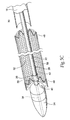
- Figs. 1A and 1B show a prosthesis delivery catheter 10.
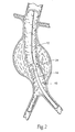
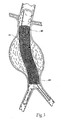
- the purpose of the catheter 10 is to (i) contain and/or restrain a prosthesis 14 prior to its deployment (see Fig. 1B ), (ii) deliver the prosthesis 14 through the vasculature to a desired location within the body, e.g., a hollow body organ or a blood vessel (see Fig. 2 ), and (iii) controllably deploy the prosthesis 14 in the desired location (see Fig. 3 ).
- the prosthesis 14 takes the form of an endovascular, self-expanding stent prosthesis.
- the prosthesis or prostheses 14 may have a wide variety of conventional configurations. It can typically comprise a fabric or some other blood semi-impermeable flexible barrier which is supported by a structure formed by stents 48.
- the stent structure can have any conventional stent configuration, such as zigzag, serpentine, expanding diamond, or combinations thereof.
- the stent structure may extend the entire length of the prosthesis, and in some instances can be longer than the fabric components of the prosthesis. Alternatively, the stent structure can cover only a small portion of the prosthesis, e.g., being present at the ends.
- the stent structure may have three or more ends when it is configured to treat bifurcated vascular regions, such as the treatment of abdominal aortic aneurysms, when the stent prosthesis extends into the iliac arteries.
- the stent structures can be spaced apart along the entire length, or at least a major portion of the entire length, of the stent-prosthesis, where individual stent structures are not connected to each other directly, but rather connected to the fabric or other flexible component of the prosthesis.
- the stent structures could be attached to one another at discrete locations, e.g., in the proximal neck region.
- Such stent structures could comprise individual stents that are connected together when incorporated into the prosthesis, or stents that are manufactured in a joined condition prior to incorporation into the prosthesis.
- the stents 48 may be elastic, e.g., comprised of a shape memory alloy elastic stainless steel, or the like.
- expanding typically comprises releasing the stent structure from a constraint to permit the stent structure to self-expand at the implantation site.
- the catheter 10 places a sheath over the stent structure, in combination with releasable restraining means coupled to the stent structure, to maintain the stent structure in a radially reduced configuration during passage into the body.
- self-expansion of the stent structure is achieved by pulling back on the sheath and release of the restraining means, to permit the stent structure to assume its larger diameter configuration.
- the stent structure may comprise a combination of a self-expanding stent and a malleable stent structure.
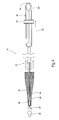
- the catheter 10 is shown being positioned over a guidewire 12 in a body lumen.
- the catheter 10 carries the prosthesis 14 in a radially reduced configuration to a targeted site.
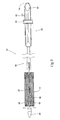
- the catheter 10 releases the radially reduced prosthesis 14, which expands radially (see Fig. 3 ).
- one or more fasteners are desirably introduced by a fastener attachment assembly to anchor the prosthesis 14 in place.
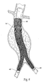
- the prosthesis 14 can be sized and configured to be either straight or bifurcated form.
- Fig. 3 depicts a completely deployed straight prosthesis 14.
- Fig. 4 depicts a completely deployed bifurcated prosthesis.
- Fig. 2 shows the targeted site as being within an abdominal aortic aneurysm.
- the targeted site can be elsewhere in the body.
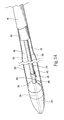
- the catheter 10 comprises an inner assembly 16, an outer sheath 18, and a handle assembly 20. These components will now be individually described in greater detail.
- the inner assembly 16 comprises a central shaft 22, which functions as a carrier for the prosthesis.
- the inner assembly also includes a catheter tip component 24, a releasing means or mechanism 28 for retaining at least a distal portion of the prosthesis 14 in a radially compressed condition prior to deployment, a retaining means or mechanism 26 for maintaining the releasing means 28 in a desired relationship with the central shaft 22 during use, and a spacer 30.
- the central shaft 22, the retaining means 26, the releasing means 28, and the spacer 30 are located within the confines of the outer sheath 18.
- the outer sheath 18 functions as an enclosure for the prosthesis on the carrier.
- the catheter tip component 24 is attached to the distal end of the central shaft 22, and the distal end of the outer sheath 18 terminates adjacent the catheter tip component 24.
- the catheter tip component 24 extends outward beyond the outer sheath 18.
- the central shaft 22, the releasing means 28, and the outer sheath 18 connect to the handle assembly 20 at the proximal end of the catheter 10 (see Fig. 1A ).
- the prosthesis 14 is contained in a cavity 32 defined between the central shaft 22 and the outer sheath 18 in the distal section of the catheter 10 (this arrangement is also shown in Fig. 1B ).
- the central shaft 22 extends from the handle assembly 20 (see Fig. 1A ) to the catheter tip component 24.
- the central shaft 22 may be made, e.g., from stainless steel or other suitable medical materials including other metals or polymers.
- the central shaft 22 desirably has at least one lumen 36 (see Fig. 5A ), with an inner diameter between 0.25 and 3.05 mm (.010 and .120 inches), preferably between 0.76 and 1.52 mm (.03 and .06 inches) and most preferably between 1.02 and 1.27 mm (.04 and .05 inches).
- the central lumen 36 allows for the insertion of a guide wire 12 up to 0.96 mm (0.038") diameter.
- the catheter tip component 24 also desirably has at least one lumen 38 (see Fig. 5A ) configured to align with at least one lumen within the central shaft 22.
- This lumen 38 allows for the insertion of a guide wire 12 through the central shaft 22 and through the catheter tip component 24 (see Fig. 2 ).
- this lumen will have an inner diameter between 0.25 and 3.05 mm (.010 and .120 inches), preferably between 0.76 and 1.52 mm (.03 and .06 inches) and most preferably between 1.02 and 1.27 mm (.04 and .05 inches).
- the catheter tip component 24 is flexible and has a long, tapered distal end and a shorter, tapered proximal end.
- the maximum diameter of the catheter tip component 24 is approximately the same as the outside diameter of the distal end of the outer sheath 18.
- the distal end of the catheter tip component 24 provides a smooth tapered transition from the lumen 38 containing the guide wire 12 to the distal edge of the outer sheath 18. This feature aids in catheter insertion and navigation through tortuous anatomy over the guide wire 12.
- the tapered section on the proximal end of the catheter tip component 24 prevents the catheter tip component 24 from inadvertently engaging the prosthesis 14, portions of the surrounding anatomy, or an introducer sheath or the like during removal of the catheter 10 from the body.
- the retaining means 26 holds the releasing means 28 in a desired, close relationship with the central shaft 22.
- the retaining means 26 orients the releasing means 28 along the axis of the central shaft 22 and allows the releasing means 28 longitudinal movement in this axis.
- the retaining means 26 includes a small hole or recess 40 in the proximal end of the catheter tip component 24 and a tube 56 having a diameter sufficiently large to accommodate both the central shaft 22 and the releasing means 28.
- Figs. 5A , 5B , and 5C the retaining means 26 includes a small hole or recess 40 in the proximal end of the catheter tip component 24 and a tube 56 having a diameter sufficiently large to accommodate both the central shaft 22 and the releasing means 28.
- the tube 56 of the retaining means 26 is located over the central shaft 22 in alignment with and adjacent to the recess 40 on the catheter tip component 24.
- the tube 56 is attached to the central shaft 22 in a manner in that retains a crescent shape lumen 42 between the tube 56 and the central shaft 22.
- the releasing means 28 extends through this lumen 42 and into the recess 40.
- the spacer 30 provides support for the outer sheath 18 and, by occupying space within the outer sheath 18, reduces the amount of air entrapped within the catheter 10.
- the distal end of the spacer 30 desirably terminates adjacent the proximal end of the prosthesis 14 (as Fig. 5B shows).
- the cavity 32 containing the prosthesis 14 extends from the proximal end of the catheter tip component 24 to the distal end of the spacer 30.
- the spacer 30 is positioned over the central shaft 22 and releasing means 28 and the proximal end of the spacer 30 is connected to the handle assembly 20.
- the spacer 30 can have an outer diameter slightly less than the inner diameter of the outer sheath 18.
- the spacer 30 can comprise a single lumen or an array of multiple lumens for passage of the various components within the spacer 30.
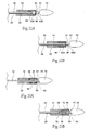
- the releasing means 28 holds the prosthesis 14 in a desired configuration prior to deployment (see Fig. 5B ) and selectively releases the prosthesis 14 for deployment (see Fig. 5C ).
- the proximal end of the releasing means 28 is connected to an actuator or control button or knob 46 in the handle assembly 20 (see Fig. 1A ).
- the releasing means 28 extends along the outside of the central shaft 22, through the inside of the spacer 30, and continues distally through the inside of the prosthesis 14.
- the releasing means 28 passes through the prosthesis 14 and the retaining means 26.
- the prosthesis 14 is retained by the releasing means 28 along the central shaft 22 in the cavity 32, which extends between the proximal end of the catheter tip component 24 and the distal end of the spacer 30.
- the releasing means 28 includes a wire 58 that extends along the central shaft 22.
- the distal end of the wire 58 passes through the crescent shape lumen 42 of the retaining means 26, and is ultimately captured in the hole or recess 40 of the retaining means 26 in the proximal end of the catheter tip component 24.
- the distal end of the wire 58 is thereby kept in a desired relationship along the central shaft 22.
- the proximal end of the wire 58 is coupled to the control button 46, such that fore and aft movement of the button 46 advances the wire 58, respectively, distally and proximally.
- the releasing means 28 includes sutures 44 and/or equivalent structures, which are attached to one or more stents 48 on the prosthesis 14.
- the sutures 44 are, in turn, looped around the wire 58 of the releasing means 28, when the wire 58 is in its distal-most position, as Fig. 5B shows.
- Proximal advancement of the wire 58 withdraws the wire 58 from the suture loops 44, as Fig. 5C shows.
- suture loops 44 are shown attached to one or more stents 48 at the distal end of the prosthesis 14. It should be appreciated, however, that suture loops 44 could additionally be attached to stents 44 elsewhere in the prosthesis 14, and/or the other components of the prosthesis 14 as well.
- the suture loops 44 and wire 56 of the embodiment of the releasing means 28 just described retain the prosthesis 14 to the central shaft (see Fig. 5B ).
- the suture loops 44 and the wire 58 keep the prosthesis 14 from moving proximally as the outer sheath 18 is retracted.
- the releasing means 28 also keeps the stents 48 that are coupled to the suture loops 44 in a radially compressed condition as the outer sheath 18 is removed.
- the suture loops 44 and wire 56 prevent the distal end of the prosthesis 14 from self-expanding until the releasing means 28 has been withdrawn.
- the withdrawal of the releasing means 28 is accomplished by operating the control button 46 to move the wire 58 proximally, withdrawing the wire 58 from the hole or recess 40 and away from the suture loops 44. Once the releasing means 28 is withdrawn, the restrained components of the prosthesis 14 are freed to self expand, as Fig. 5C shows.
- the releasing means 28 is coupled to one restrained component of the prosthesis 14. It should be appreciated, however, that the releasing means 28 can be coupled to the prosthesis 14 at two or more restrained regions, so that withdrawal of the releasing means 28 frees the prosthesis at two or more restrained regions. It should also be appreciated that the releasing means 28 can comprise more than a single releasing element. For example, multiple, individual releasing wires 58 could be coupled to the prosthesis 14 at different regions, so that release of separate regions of the prosthesis 14 can be individually controlled.
- the outer sheath 18 also serves to restrain the stents 48 on the prosthesis 14 from expanding and allows for a controlled deployment of the prosthesis 14 within the body.
- the outer sheath 18 is connected to an actuator or a collar or knob 50 on the handle assembly 20.
- the outer sheath 18 extends distally over the spacer 30 and prosthesis 14 and terminates adjacent the proximal end of the catheter tip component 24.
- the outer sheath 18 can be made of a polymer tube and be free of structural reinforcement.
- the outer sheath 18 is tapered due to the difference in outer diameters of the catheter tip component and the spacer 30 (see Fig. 5A ).
- the larger diameter of the outer sheath 18 is intended to contain the main body of the prosthesis 14 and the smaller diameter would contain the leg portion or portions of the prosthesis 14, if present (as in the embodiment shown in Fig. 4 ).
- the smaller diameter continues proximally to the handle assembly 20. This tapered feature of the outer sheath 18 also allows for better blood circulation past the catheter.
- the handle assembly 20 provides the operator with longitudinal and rotational control of the catheter 10 within the body and provides access to the actuator or control means for deploying the prosthesis 14.
- the handle assembly 20 comprises a handle body 52 and the sliding knob or collar 50 which is connected to the proximal and the of the outer sheath 18, and the knob or button 46 which is attached to proximal end of the releasing means 28.
- the central shaft 22 is captured within the handle and has a guide wire receiving luer 34 connected to its proximal end, which is located at the proximal end of the handle assembly 20. This design prevents the position of the prosthesis 14 from moving relative to the handle body 52 while the outer sheath 18 is retracted.
- the sliding knob 50 is moved proximally until the distal end of the outer sheath 18 is free of the prosthesis 14 (see Fig. 8 ).
- the portion or portions of the prosthesis 14 that are not coupled to the releasing means 28 (which, in the illustrated embodiment comprise the proximal region of the prosthesis 14) are free to self-expand, as Fig. 8 shows.
- the portions of the prosthesis 14 that are coupled to the releasing means 58 (which, in the illustrated embodiment comprise only the distal region of the prosthesis 14) are still restrained from self-expansion, despite withdrawal of the outer sheath 18, as Fig. 8 also shows.
- the stent structure of the prosthesis 14 is thereby kept restrained closely against the central shaft tube 22 while the outer sheath 18 is retracted.
- the retaining means 26 prevents the prosthesis 14 from moving relative to the central tube 22 during retraction of the outer sheath 18, which potentially minimizes blood flow through the prosthesis 14 during the deployment process.
- the prosthesis 14 is not "pushed out” of the catheter.
- the prosthesis 14 therefore need not have longitudinal stiffness or a stent structure with a "spine".
- the sliding button 46 is moved proximally until the distal end of the releasing means 28 is withdrawn from the restraining means 26.
- the prosthesis is thereby free to fully self-expand, as Fig. 9 and Fig. 5C show.
- the prosthesis 14 is not released immediately from distal end to proximal end as the sheath 18 is withdrawn.
- the prosthesis 14 is pulled in tension, which "stretches" the prosthesis to its proper length and stent spacing.
- the distal stent or stents 48 are released in a secondary operation, which follows the withdrawal of the outer sheath 18 (as shown in Figs. 5C , 8 , and 9 ).
- Final placement of distal end of the prosthesis 14 can therefore comprise a final step in the deployment process.
- the catheter 10 is navigated over the guide wire 12 to the desired location within the body (as Fig. 2 shows).
- deployment of the prosthesis 14 is achieved in a two step process.
- the outer sheath 18 is retracted and exposes the prosthesis 14 (as Figs. 6 and 7 show).
- the unrestrained portion or portions of the prosthesis 14 self-expand, as Fig. 8 show.
- Figs. 6 and 7 show, during retraction of the outer sheath 18, the prosthesis 14 maintains its position relative to the central shaft 22 due to the releasing means 28 connected to the prosthesis 44.
- the control button or knob 46 on the handle assembly 20 is moved proximally (see Figs. 8 and 9 ). This causes the distal end of the releasing means 28 to be withdrawn and allows the restrained stent or stents 44, and the prosthesis 14 as a whole, to self-expand radially (as Figs. 5C and 9 show).
- the prosthesis 14 enlarges to contact the internal walls of the vessel or hollow body organ, as Fig. 3 shows.
- the catheter 10 can then be withdrawn (as Fig. 10 shows).
- the distal end of a movable component of the releasing means 28 extends along the central shaft 22 in a manner prescribed and controlled by the restraining means 26, i.e., between a tube 56 carried by the central shaft 22 and a recess 40 located in the proximal end of the catheter tip component 24. It is in the region between the tube 56 and the recess 40, that a stationary component of the releasing means 28, which is attached to the prosthesis 14 (e.g., the suture loops 44), is operatively coupled to the movable component of the releasing means 28.
- the restraining means 26 serves to maintain the movable component 58 of the releasing means 28 in a desired operative alignment with the central shaft 22, as well as in a desired operative relationship with the stationary component 44 of the releasing means 28, such that quick and certain release of the prosthesis 14 occurs.
- the releasing means 28 and the restraining means 26 can be variously constructed to meet this objective.
- the distal end of the movable component 58 of the releasing means 28 extends along the central shaft 22 in a manner prescribed and controlled by the restraining means 26, i.e., between adjacent, spaced apart tubes 60A and 60B, without dependence upon additional support by the catheter tip component 24.
- Each tube 60A and 60B surrounds the central shaft 22 in the same fashion as the single tube 56 shown in Figs. 11A to 11C .
- the movable component 58 of the releasing means 28 is held in the region between the two tubes 60A and 60B in operative association with the stationary component 44 of the releasing means 28, and can be quickly and certainly withdrawn from this region to release the prosthesis 14.
- the distal end of the movable component 58 of the releasing means 28 extends along the central shaft 22 between adjacent, spaced apart external tubes 62A and 62B, again without dependence upon additional support by the catheter tip component 24.
- the tubes 62A and 62B project along the exterior of the central shaft 22, but do not surround it.
- a single external support tube like tube 62A or 62B could, alternatively, be used in a hybrid combination with the recess 40 in the catheter tip component 24, if desired.
- the distal end of the movable component 58 of the releasing means 28 extends within a lumen in the central shaft 22, exiting through an aperture 64 in the shaft 22 and into a recess 40 in the catheter tip component 24.
- the movable component 58 of the releasing means 28 is held in the region between the aperture 64 and the recess 40 in operative association with the stationary component 44 of the releasing means 28, and can be quickly and certainly withdrawn from this region to release the prosthesis 14.
- a similar alternative arrangement see Fig.
- the distal end of the movable component 58 of the releasing means 28 extends within a lumen 68 of the central shaft 22 between adjacent, spaced apart apertures 70 and 72.
- the movable component 58 exits the aperture 72 and enters a recess 40 in the catheter tip component 24.
- the movable component 58 of the releasing means 28 is held in the region between the aperture 72 and the recess 40 in operative association with the stationary component 44 of the releasing means 28, and can be quickly and certainly withdrawn from this region to release the prosthesis 14.
- the restraining means 26 includes a single tube 74 carried by the central shaft 22, through which the movable component 58 of the releasing means 28 passes.
- the tube 74 can comprise a surrounding tube of the type shown in Fig. 12A (as Figs. 14A and 14B show) or an external tube of the type shown in Fig. 12B .
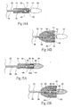
- the releasing means 28 includes a suture loop 76 carried by the proximal end of the catheter tip component 24 and a cutting element 78 carried on the distal end of the movable component 58 of the releasing means 28.
- the suture loop 76 passes through the suture loops 44 on the prosthesis 14, as well as through the cutting element 78.
- the cutting element 78 on the distal end of the movable component 58 of the releasing means 28 extends along the central shaft 22 in a manner prescribed and controlled by the restraining means 26, i.e., through and beyond the tube 74, and in operative association with the suture loops 44 and 76, which, in this embodiment, comprise the stationary components of the releasing means 28. This occurs without dependence upon additional support by the catheter tip component 24. withdrawal of the movable component 58 moves the cutting element 78 through the suture loop 76, cutting the suture loop 76 and releasing the prosthesis 14 (as Fig. 14B shows).
- the restraining means 26 includes a single tube 80 carried by the central shaft 22, through which the movable component 58 of the releasing means 28 passes.
- the tube 80 can comprise a surrounding tube of the type shown in Fig. 12A (as Figs. 15A and 15B show) or an external tube of the type shown in Fig. 12B .
- the releasing means 28 includes a wedge element 84 carried on the distal end of the movable component 58 of the releasing means 28.
- the wedge element 84 nests within a mating wedge surface 86 formed in the proximal end of the catheter tip component 24. Advancement of the movable component 58 moves the wedge element 84 into the registration within the wedge surface 86 (as Fig. 15A shows) and out of registration with the wedge surface 86 (as Fig. 15B shows).
- the releasing means 28 in this arrangement further includes alternative embodiments of suture loops 82 or 82', which are pinched between the wedge element 84 and the wedge surface 86 when the element 84 and the surface 86 are in registration, as Fig. 15A shows.
- the embodiment of the suture loop 82 comprises a closed loop 82 carried by a prosthesis stent 48.
- the embodiment of the suture loop 82' comprises an open loop 82' carried by the proximal end of the catheter tip component 24 and looped through a prosthesis stent 48.
- expansion of the prosthesis 14 is restrained (as Fig. 15A shows).
- the wedge element 84 is freed from registration within the wedge surface 86, freeing the loops 82 or 82', thereby releasing the prosthesis 14 for expansion, as Fig. 15B shows.
Landscapes
- Health & Medical Sciences (AREA)
- Engineering & Computer Science (AREA)
- Biomedical Technology (AREA)
- Life Sciences & Earth Sciences (AREA)
- General Health & Medical Sciences (AREA)
- Transplantation (AREA)
- Heart & Thoracic Surgery (AREA)
- Vascular Medicine (AREA)
- Cardiology (AREA)
- Animal Behavior & Ethology (AREA)
- Oral & Maxillofacial Surgery (AREA)
- Public Health (AREA)
- Veterinary Medicine (AREA)
- Gastroenterology & Hepatology (AREA)
- Pulmonology (AREA)
- Prostheses (AREA)
- Media Introduction/Drainage Providing Device (AREA)
- Infusion, Injection, And Reservoir Apparatuses (AREA)
- Medicines That Contain Protein Lipid Enzymes And Other Medicines (AREA)
Applications Claiming Priority (2)
| Application Number | Priority Date | Filing Date | Title |
|---|---|---|---|
| US10/692,283 US7147657B2 (en) | 2003-10-23 | 2003-10-23 | Prosthesis delivery systems and methods |
| PCT/US2004/027587 WO2005044073A2 (en) | 2003-10-23 | 2004-08-25 | Prosthesis delivery systems and methods |
Publications (3)
| Publication Number | Publication Date |
|---|---|
| EP1682039A2 EP1682039A2 (en) | 2006-07-26 |
| EP1682039A4 EP1682039A4 (en) | 2007-04-18 |
| EP1682039B1 true EP1682039B1 (en) | 2009-08-05 |
Family
ID=34522082
Family Applications (1)
| Application Number | Title | Priority Date | Filing Date |
|---|---|---|---|
| EP04782144A Expired - Lifetime EP1682039B1 (en) | 2003-10-23 | 2004-08-25 | Prosthesis delivery systems |
Country Status (11)
| Country | Link |
|---|---|
| US (3) | US7147657B2 (enExample) |
| EP (1) | EP1682039B1 (enExample) |
| JP (2) | JP4912883B2 (enExample) |
| CN (1) | CN1870950B (enExample) |
| AT (1) | ATE438362T1 (enExample) |
| AU (1) | AU2004287353A1 (enExample) |
| CA (1) | CA2539265A1 (enExample) |
| DE (1) | DE602004022446D1 (enExample) |
| DK (1) | DK1682039T3 (enExample) |
| ES (1) | ES2356352T3 (enExample) |
| WO (1) | WO2005044073A2 (enExample) |
Cited By (2)
| Publication number | Priority date | Publication date | Assignee | Title |
|---|---|---|---|---|
| US9320591B2 (en) | 2001-11-28 | 2016-04-26 | Medtronic Vascular, Inc. | Devices, systems, and methods for prosthesis delivery and implantation, including the use of a fastener tool |
| US10098770B2 (en) | 2001-11-28 | 2018-10-16 | Medtronic Vascular, Inc. | Endovascular aneurysm devices, systems, and methods |
Families Citing this family (209)
| Publication number | Priority date | Publication date | Assignee | Title |
|---|---|---|---|---|
| US7491232B2 (en) * | 1998-09-18 | 2009-02-17 | Aptus Endosystems, Inc. | Catheter-based fastener implantation apparatus and methods with implantation force resolution |
| WO2003003944A2 (en) | 2001-07-06 | 2003-01-16 | Angiomed Gmbh & Co. Medizintechnik Kg | Delivery system having a rapid pusher assembly for self-expanding stent, and stent exchange configuration |
| GB0123633D0 (en) | 2001-10-02 | 2001-11-21 | Angiomed Ag | Stent delivery system |
| US20110087320A1 (en) * | 2001-11-28 | 2011-04-14 | Aptus Endosystems, Inc. | Devices, Systems, and Methods for Prosthesis Delivery and Implantation, Including a Prosthesis Assembly |
| JP4405262B2 (ja) | 2001-11-28 | 2010-01-27 | アプタス エンドシステムズ, インコーポレイテッド | 血管内動脈瘤修復システム |
| US8231639B2 (en) | 2001-11-28 | 2012-07-31 | Aptus Endosystems, Inc. | Systems and methods for attaching a prosthesis within a body lumen or hollow organ |
| US20050177180A1 (en) | 2001-11-28 | 2005-08-11 | Aptus Endosystems, Inc. | Devices, systems, and methods for supporting tissue and/or structures within a hollow body organ |
| US7147657B2 (en) | 2003-10-23 | 2006-12-12 | Aptus Endosystems, Inc. | Prosthesis delivery systems and methods |
| US20090112303A1 (en) * | 2001-11-28 | 2009-04-30 | Lee Bolduc | Devices, systems, and methods for endovascular staple and/or prosthesis delivery and implantation |
| US9320503B2 (en) | 2001-11-28 | 2016-04-26 | Medtronic Vascular, Inc. | Devices, system, and methods for guiding an operative tool into an interior body region |
| DE60311806T2 (de) | 2002-06-11 | 2007-10-31 | Tyco Healthcare Group Lp, Norwalk | Klammer zur Befestigung von Hernia-Netz |
| GB0327306D0 (en) * | 2003-11-24 | 2003-12-24 | Angiomed Gmbh & Co | Catheter device |
| US8568467B2 (en) | 2003-01-15 | 2013-10-29 | Angiomed Gmbh & Co. Medizintechnik Kg | Trans-luminal surgical device |
| US8926637B2 (en) | 2003-06-13 | 2015-01-06 | Covidien Lp | Multiple member interconnect for surgical instrument and absorbable screw fastener |
| EP2298184A1 (en) | 2003-06-13 | 2011-03-23 | Tyco Healthcare Group LP | Multiple member interconnect for surgical instrument and absorbable screw fastener |
| US20070198078A1 (en) | 2003-09-03 | 2007-08-23 | Bolton Medical, Inc. | Delivery system and method for self-centering a Proximal end of a stent graft |
| US20080264102A1 (en) | 2004-02-23 | 2008-10-30 | Bolton Medical, Inc. | Sheath Capture Device for Stent Graft Delivery System and Method for Operating Same |
| US7763063B2 (en) | 2003-09-03 | 2010-07-27 | Bolton Medical, Inc. | Self-aligning stent graft delivery system, kit, and method |
| US9198786B2 (en) | 2003-09-03 | 2015-12-01 | Bolton Medical, Inc. | Lumen repair device with capture structure |
| US11259945B2 (en) | 2003-09-03 | 2022-03-01 | Bolton Medical, Inc. | Dual capture device for stent graft delivery system and method for capturing a stent graft |
| US8292943B2 (en) | 2003-09-03 | 2012-10-23 | Bolton Medical, Inc. | Stent graft with longitudinal support member |
| US8500792B2 (en) | 2003-09-03 | 2013-08-06 | Bolton Medical, Inc. | Dual capture device for stent graft delivery system and method for capturing a stent graft |
| US11596537B2 (en) | 2003-09-03 | 2023-03-07 | Bolton Medical, Inc. | Delivery system and method for self-centering a proximal end of a stent graft |
| US10478179B2 (en) | 2004-04-27 | 2019-11-19 | Covidien Lp | Absorbable fastener for hernia mesh fixation |
| EP1765221A1 (en) * | 2004-06-16 | 2007-03-28 | Cook Incorporated | Thoracic deployment device and stent graft |
| US7678121B1 (en) | 2004-12-23 | 2010-03-16 | Cardica, Inc. | Surgical stapling tool |
| US7462185B1 (en) | 2004-12-23 | 2008-12-09 | Cardican Inc. | Intravascular stapling tool |
| WO2006097931A2 (en) | 2005-03-17 | 2006-09-21 | Valtech Cardio, Ltd. | Mitral valve treatment techniques |
| US7344544B2 (en) * | 2005-03-28 | 2008-03-18 | Cardica, Inc. | Vascular closure system |
| US8333777B2 (en) | 2005-04-22 | 2012-12-18 | Benvenue Medical, Inc. | Catheter-based tissue remodeling devices and methods |
| US8951285B2 (en) | 2005-07-05 | 2015-02-10 | Mitralign, Inc. | Tissue anchor, anchoring system and methods of using the same |
| US8123795B1 (en) | 2005-10-03 | 2012-02-28 | Cardica, Inc. | System for attaching an abdominal aortic stent or the like |
| EP2301487B1 (en) * | 2006-05-12 | 2014-09-17 | Covidien LP | Implant and delivery system with multiple marker interlocks |
| US9585743B2 (en) | 2006-07-31 | 2017-03-07 | Edwards Lifesciences Cardiaq Llc | Surgical implant devices and methods for their manufacture and use |
| EP3360509B1 (en) | 2006-07-31 | 2022-06-22 | Syntheon TAVR, LLC | Sealable endovascular implants |
| US7875053B2 (en) * | 2006-09-15 | 2011-01-25 | Cardica, Inc. | Apparatus and method for closure of patent foramen ovale |
| US9278017B2 (en) * | 2006-11-30 | 2016-03-08 | Cook Medical Technologies Llc | Implant release mechanism |
| US9883943B2 (en) | 2006-12-05 | 2018-02-06 | Valtech Cardio, Ltd. | Implantation of repair devices in the heart |
| US11259924B2 (en) | 2006-12-05 | 2022-03-01 | Valtech Cardio Ltd. | Implantation of repair devices in the heart |
| US11660190B2 (en) | 2007-03-13 | 2023-05-30 | Edwards Lifesciences Corporation | Tissue anchors, systems and methods, and devices |
| US9149379B2 (en) * | 2007-07-16 | 2015-10-06 | Cook Medical Technologies Llc | Delivery device |
| US9566178B2 (en) * | 2010-06-24 | 2017-02-14 | Edwards Lifesciences Cardiaq Llc | Actively controllable stent, stent graft, heart valve and method of controlling same |
| JP5364933B2 (ja) * | 2007-08-13 | 2013-12-11 | クック・メディカル・テクノロジーズ・リミテッド・ライアビリティ・カンパニー | 配置装置 |
| CN101861134B (zh) * | 2007-09-11 | 2013-06-26 | 彼鲁兹实验室 | 血液循环管道的治疗装置 |
| US20090093826A1 (en) * | 2007-10-05 | 2009-04-09 | Cardica, Inc. | Patent Foramen Ovale Closure System |
| GB2475494B (en) | 2009-11-18 | 2011-11-23 | Cook William Europ | Stent graft and introducer assembly |
| US9180030B2 (en) | 2007-12-26 | 2015-11-10 | Cook Medical Technologies Llc | Low profile non-symmetrical stent |
| US9226813B2 (en) | 2007-12-26 | 2016-01-05 | Cook Medical Technologies Llc | Low profile non-symmetrical stent |
| US8574284B2 (en) | 2007-12-26 | 2013-11-05 | Cook Medical Technologies Llc | Low profile non-symmetrical bare alignment stents with graft |
| GB2476451A (en) * | 2009-11-19 | 2011-06-29 | Cook William Europ | Stent Graft |
| US8382829B1 (en) | 2008-03-10 | 2013-02-26 | Mitralign, Inc. | Method to reduce mitral regurgitation by cinching the commissure of the mitral valve |
| US10813779B2 (en) * | 2008-04-25 | 2020-10-27 | CARDINAL HEALTH SWITZERLAND 515 GmbH | Stent attachment and deployment mechanism |
| CA2725736C (en) | 2008-06-04 | 2013-09-17 | Gore Enterprise Holdings, Inc. | Controlled deployable medical device and method of making the same |
| CA2727000C (en) | 2008-06-04 | 2014-01-07 | Gore Enterprise Holdings, Inc. | Controlled deployable medical device and method of making the same |
| GB0810749D0 (en) | 2008-06-11 | 2008-07-16 | Angiomed Ag | Catherter delivery device |
| US9750625B2 (en) | 2008-06-11 | 2017-09-05 | C.R. Bard, Inc. | Catheter delivery device |
| JP5484458B2 (ja) | 2008-06-30 | 2014-05-07 | ボルトン メディカル インコーポレイテッド | 腹部大動脈瘤システム |
| US8652202B2 (en) | 2008-08-22 | 2014-02-18 | Edwards Lifesciences Corporation | Prosthetic heart valve and delivery apparatus |
| EP2617388B2 (en) | 2008-10-10 | 2019-11-06 | Boston Scientific Scimed, Inc. | Medical devices and delivery systems for delivering medical devices |
| CA2740867C (en) | 2008-10-16 | 2018-06-12 | Aptus Endosystems, Inc. | Devices, systems, and methods for endovascular staple and/or prosthesis delivery and implantation |
| US8241351B2 (en) | 2008-12-22 | 2012-08-14 | Valtech Cardio, Ltd. | Adjustable partial annuloplasty ring and mechanism therefor |
| US10517719B2 (en) | 2008-12-22 | 2019-12-31 | Valtech Cardio, Ltd. | Implantation of repair devices in the heart |
| US8715342B2 (en) | 2009-05-07 | 2014-05-06 | Valtech Cardio, Ltd. | Annuloplasty ring with intra-ring anchoring |
| US8911494B2 (en) | 2009-05-04 | 2014-12-16 | Valtech Cardio, Ltd. | Deployment techniques for annuloplasty ring |
| WO2010073246A2 (en) | 2008-12-22 | 2010-07-01 | Valtech Cardio, Ltd. | Adjustable annuloplasty devices and adjustment mechanisms therefor |
| WO2010078352A1 (en) * | 2008-12-30 | 2010-07-08 | Wilson-Cook Medical Inc. | Delivery device |
| US20100174292A1 (en) * | 2009-01-07 | 2010-07-08 | Vanderbilt University | Surgical instrument for placing a prosthesis into a target area of a living subject |
| US8876807B2 (en) | 2009-01-19 | 2014-11-04 | W. L. Gore & Associates, Inc. | Forced deployment sequence |
| US8858610B2 (en) | 2009-01-19 | 2014-10-14 | W. L. Gore & Associates, Inc. | Forced deployment sequence |
| US20100204717A1 (en) * | 2009-02-12 | 2010-08-12 | Cardica, Inc. | Surgical Device for Multiple Clip Application |
| US8353956B2 (en) | 2009-02-17 | 2013-01-15 | Valtech Cardio, Ltd. | Actively-engageable movement-restriction mechanism for use with an annuloplasty structure |
| AU2010223953B2 (en) * | 2009-03-13 | 2014-05-01 | Bolton Medical, Inc. | System and method for deploying an endoluminal prosthesis at a surgical site |
| GB2469072A (en) * | 2009-03-31 | 2010-10-06 | Royal Brompton & Harefield Nhs | Guidewire with Anchor for a catheter |
| US7875029B1 (en) | 2009-05-04 | 2011-01-25 | Cardica, Inc. | Surgical device switchable between clip application and coagulation modes |
| US9968452B2 (en) | 2009-05-04 | 2018-05-15 | Valtech Cardio, Ltd. | Annuloplasty ring delivery cathethers |
| US12485010B2 (en) | 2009-05-07 | 2025-12-02 | Edwards Lifesciences Innovation (Israel) Ltd. | Multiple anchor delivery tool |
| JP5596028B2 (ja) * | 2009-05-27 | 2014-09-24 | 克彦 岡 | 管状治療具留置装置及び管状治療具留置装置用先端チップ |
| US8771333B2 (en) | 2009-06-23 | 2014-07-08 | Cordis Corporation | Stent-graft securement device |
| US10098737B2 (en) | 2009-10-29 | 2018-10-16 | Valtech Cardio, Ltd. | Tissue anchor for annuloplasty device |
| US9180007B2 (en) | 2009-10-29 | 2015-11-10 | Valtech Cardio, Ltd. | Apparatus and method for guide-wire based advancement of an adjustable implant |
| US9757263B2 (en) | 2009-11-18 | 2017-09-12 | Cook Medical Technologies Llc | Stent graft and introducer assembly |
| DE102009055969A1 (de) * | 2009-11-27 | 2011-06-01 | Transcatheter Technologies Gmbh | Vorrichtung und Set zum Falten oder Entfalten eines medizinischen Implantats und Verfahren |
| CA2782385A1 (en) | 2009-12-01 | 2011-06-09 | Altura Medical, Inc. | Modular endograft devices and associated systems and methods |
| EP2506777B1 (en) | 2009-12-02 | 2020-11-25 | Valtech Cardio, Ltd. | Combination of spool assembly coupled to a helical anchor and delivery tool for implantation thereof |
| WO2011094527A1 (en) * | 2010-01-29 | 2011-08-04 | Cook Medical Technologies Llc | Mechanically expandable delivery and dilation systems |
| US8926693B2 (en) | 2010-02-17 | 2015-01-06 | Medtronic, Inc. | Heart valve delivery catheter with safety button |
| US8926692B2 (en) * | 2010-04-09 | 2015-01-06 | Medtronic, Inc. | Transcatheter prosthetic heart valve delivery device with partial deployment and release features and methods |
| PL3231401T3 (pl) | 2010-06-24 | 2020-09-21 | CARDINAL HEALTH SWITZERLAND 515 GmbH | Urządzenie do wyciągania elastycznego elementu z urządzenia medycznego |
| CA2806234C (en) | 2010-07-30 | 2015-03-24 | Cook Medical Technologies Llc | Controlled release and recapture prosthetic deployment device |
| US10321998B2 (en) | 2010-09-23 | 2019-06-18 | Transmural Systems Llc | Methods and systems for delivering prostheses using rail techniques |
| GB2485762B (en) * | 2010-11-12 | 2012-12-05 | Cook Medical Technologies Llc | Introducer assembly and dilator tip therefor |
| JP2012139471A (ja) * | 2011-01-06 | 2012-07-26 | Nippon Zeon Co Ltd | ステントデリバリー装置 |
| US9744033B2 (en) | 2011-04-01 | 2017-08-29 | W.L. Gore & Associates, Inc. | Elastomeric leaflet for prosthetic heart valves |
| US12502276B2 (en) | 2011-05-16 | 2025-12-23 | Edwards Lifesciences Corporation | Inversion delivery device and method for a prosthesis |
| US10117765B2 (en) | 2011-06-14 | 2018-11-06 | W.L. Gore Associates, Inc | Apposition fiber for use in endoluminal deployment of expandable implants |
| EP3725269A1 (en) | 2011-06-23 | 2020-10-21 | Valtech Cardio, Ltd. | Closure element for use with annuloplasty structure |
| US10792152B2 (en) | 2011-06-23 | 2020-10-06 | Valtech Cardio, Ltd. | Closed band for percutaneous annuloplasty |
| US9554806B2 (en) | 2011-09-16 | 2017-01-31 | W. L. Gore & Associates, Inc. | Occlusive devices |
| US9549817B2 (en) | 2011-09-22 | 2017-01-24 | Transmural Systems Llc | Devices, systems and methods for repairing lumenal systems |
| US12364596B2 (en) | 2011-10-21 | 2025-07-22 | Edwards Lifesciences Cardiaq Llc | Actively controllable stent, stent graft, heart valve and method of controlling same |
| US9827093B2 (en) | 2011-10-21 | 2017-11-28 | Edwards Lifesciences Cardiaq Llc | Actively controllable stent, stent graft, heart valve and method of controlling same |
| US8945146B2 (en) | 2011-10-24 | 2015-02-03 | Medtronic, Inc. | Delivery system assemblies and associated methods for implantable medical devices |
| US8858623B2 (en) | 2011-11-04 | 2014-10-14 | Valtech Cardio, Ltd. | Implant having multiple rotational assemblies |
| EP3970627B1 (en) | 2011-11-08 | 2023-12-20 | Edwards Lifesciences Innovation (Israel) Ltd. | Controlled steering functionality for implant-delivery tool |
| US9782282B2 (en) | 2011-11-14 | 2017-10-10 | W. L. Gore & Associates, Inc. | External steerable fiber for use in endoluminal deployment of expandable devices |
| US9877858B2 (en) | 2011-11-14 | 2018-01-30 | W. L. Gore & Associates, Inc. | External steerable fiber for use in endoluminal deployment of expandable devices |
| US9216293B2 (en) * | 2011-11-17 | 2015-12-22 | Medtronic, Inc. | Delivery system assemblies for implantable medical devices |
| US8721587B2 (en) | 2011-11-17 | 2014-05-13 | Medtronic, Inc. | Delivery system assemblies and associated methods for implantable medical devices |
| CN102488576B (zh) * | 2011-11-25 | 2014-07-16 | 北京华脉泰科医疗器械有限公司 | 一种覆膜支架的输送释放装置 |
| WO2013088327A1 (en) | 2011-12-12 | 2013-06-20 | David Alon | Heart valve repair device |
| US9510945B2 (en) * | 2011-12-20 | 2016-12-06 | Boston Scientific Scimed Inc. | Medical device handle |
| EP3424469A1 (en) | 2012-02-22 | 2019-01-09 | Syntheon TAVR, LLC | Actively controllable stent, stent graft and heart valve |
| US9375308B2 (en) | 2012-03-13 | 2016-06-28 | W. L. Gore & Associates, Inc. | External steerable fiber for use in endoluminal deployment of expandable devices |
| BR112014025430A2 (pt) | 2012-04-12 | 2020-03-10 | Bolton Medical, Inc. | Dispositivo de envio protético vascular e método de uso |
| CN104684504B (zh) * | 2012-05-16 | 2017-06-23 | Hlt股份有限公司 | 用于假体的倒转传输设备和方法 |
| US9144510B2 (en) | 2012-06-13 | 2015-09-29 | Cook Medical Technologies Llc | Systems and methods for deploying a portion of a stent using at least one coiled member |
| US9364355B2 (en) | 2012-06-13 | 2016-06-14 | Cook Medical Technologies Llc | Systems and methods for deploying a portion of a stent using at least one coiled member |
| US20140046429A1 (en) | 2012-08-10 | 2014-02-13 | Altura Medical, Inc. | Stent delivery systems and associated methods |
| CA2885354A1 (en) | 2012-09-29 | 2014-04-03 | Mitralign, Inc. | Plication lock delivery system and method of use thereof |
| US9949828B2 (en) | 2012-10-23 | 2018-04-24 | Valtech Cardio, Ltd. | Controlled steering functionality for implant-delivery tool |
| EP2911593B1 (en) | 2012-10-23 | 2020-03-25 | Valtech Cardio, Ltd. | Percutaneous tissue anchor techniques |
| US12053378B2 (en) | 2012-11-07 | 2024-08-06 | Transmural Systems Llc | Devices, systems and methods for repairing lumenal systems |
| WO2014087402A1 (en) | 2012-12-06 | 2014-06-12 | Valtech Cardio, Ltd. | Techniques for guide-wire based advancement of a tool |
| US9687373B2 (en) | 2012-12-21 | 2017-06-27 | Cook Medical Technologies Llc | Systems and methods for securing and releasing a portion of a stent |
| US9655756B2 (en) | 2012-12-21 | 2017-05-23 | Cook Medical Technologies Llc | Systems and methods for deploying a portion of a stent using an auger-style device |
| US10350096B2 (en) * | 2012-12-26 | 2019-07-16 | Cook Medical Technologies Llc | Expandable stent-graft system having diameter reducing connectors |
| US9351733B2 (en) | 2013-01-18 | 2016-05-31 | Covidien Lp | Surgical fastener applier |
| WO2014134183A1 (en) | 2013-02-26 | 2014-09-04 | Mitralign, Inc. | Devices and methods for percutaneous tricuspid valve repair |
| US9358010B2 (en) | 2013-03-12 | 2016-06-07 | Covidien Lp | Flex cable and spring-loaded tube for tacking device |
| US9308108B2 (en) | 2013-03-13 | 2016-04-12 | Cook Medical Technologies Llc | Controlled release and recapture stent-deployment device |
| US9867620B2 (en) | 2013-03-14 | 2018-01-16 | Covidien Lp | Articulation joint for apparatus for endoscopic procedures |
| US10449333B2 (en) | 2013-03-14 | 2019-10-22 | Valtech Cardio, Ltd. | Guidewire feeder |
| US9439751B2 (en) | 2013-03-15 | 2016-09-13 | Bolton Medical, Inc. | Hemostasis valve and delivery systems |
| US9737426B2 (en) | 2013-03-15 | 2017-08-22 | Altura Medical, Inc. | Endograft device delivery systems and associated methods |
| US9724195B2 (en) | 2013-03-15 | 2017-08-08 | Mitralign, Inc. | Translation catheters and systems |
| US11911258B2 (en) | 2013-06-26 | 2024-02-27 | W. L. Gore & Associates, Inc. | Space filling devices |
| US10085746B2 (en) | 2013-06-28 | 2018-10-02 | Covidien Lp | Surgical instrument including rotating end effector and rotation-limiting structure |
| US9668730B2 (en) | 2013-06-28 | 2017-06-06 | Covidien Lp | Articulating apparatus for endoscopic procedures with timing system |
| US9358004B2 (en) | 2013-06-28 | 2016-06-07 | Covidien Lp | Articulating apparatus for endoscopic procedures |
| US9351728B2 (en) | 2013-06-28 | 2016-05-31 | Covidien Lp | Articulating apparatus for endoscopic procedures |
| US20150032130A1 (en) | 2013-07-24 | 2015-01-29 | Covidien Lp | Expanding absorbable tack |
| US10070857B2 (en) | 2013-08-31 | 2018-09-11 | Mitralign, Inc. | Devices and methods for locating and implanting tissue anchors at mitral valve commissure |
| US9925045B2 (en) | 2013-10-21 | 2018-03-27 | Medtronic Vascular Galway | Systems, devices and methods for transcatheter valve delivery |
| US10299793B2 (en) | 2013-10-23 | 2019-05-28 | Valtech Cardio, Ltd. | Anchor magazine |
| US9610162B2 (en) | 2013-12-26 | 2017-04-04 | Valtech Cardio, Ltd. | Implantation of flexible implant |
| US20170014115A1 (en) | 2014-03-27 | 2017-01-19 | Transmural Systems Llc | Devices and methods for closure of transvascular or transcameral access ports |
| CN106455936B (zh) | 2014-04-02 | 2019-03-08 | 柯惠有限合伙公司 | 用于内窥镜手术的外科紧固件施加装置、套件和方法 |
| FR3023703B1 (fr) | 2014-07-17 | 2021-01-29 | Cormove | Dispositif de traitement d'un conduit de circulation du sang |
| EP4331503A3 (en) | 2014-10-14 | 2024-06-05 | Edwards Lifesciences Innovation (Israel) Ltd. | Leaflet-restraining techniques |
| US10016293B2 (en) | 2014-12-29 | 2018-07-10 | Cook Medical Technologies Llc | Prosthesis delivery systems having an atraumatic tip for use with trigger wires |
| PL3991697T3 (pl) | 2015-01-11 | 2025-03-03 | Ascyrus Medical, Llc | Urządzenie hybrydowe do chirurgicznej naprawy aorty |
| US20160256269A1 (en) | 2015-03-05 | 2016-09-08 | Mitralign, Inc. | Devices for treating paravalvular leakage and methods use thereof |
| US20160296352A1 (en) * | 2015-04-13 | 2016-10-13 | Cook Medical Technologies Llc | Axial lock and release stent deployment system |
| SG11201708397PA (en) | 2015-04-30 | 2017-11-29 | Valtech Cardio Ltd | Annuloplasty technologies |
| CN114652385A (zh) | 2015-05-14 | 2022-06-24 | W.L.戈尔及同仁股份有限公司 | 用于闭塞心耳的装置 |
| WO2016187401A1 (en) * | 2015-05-20 | 2016-11-24 | Cook Medical Technologies Llc | Stent delivery system |
| ES2921535T3 (es) | 2015-06-18 | 2022-08-29 | Ascyrus Medical Llc | Injerto aórtico ramificado |
| US10779940B2 (en) | 2015-09-03 | 2020-09-22 | Boston Scientific Scimed, Inc. | Medical device handle |
| EP3349687B1 (en) | 2015-09-15 | 2020-09-09 | THE UNITED STATES OF AMERICA, represented by the S | Devices for effectuating percutaneous glenn and fontan procedures |
| US10751182B2 (en) | 2015-12-30 | 2020-08-25 | Edwards Lifesciences Corporation | System and method for reshaping right heart |
| EP3397207B1 (en) | 2015-12-30 | 2026-04-01 | Edwards Lifesciences Corporation | System for reducing tricuspid regurgitation |
| US10799676B2 (en) | 2016-03-21 | 2020-10-13 | Edwards Lifesciences Corporation | Multi-direction steerable handles for steering catheters |
| US11219746B2 (en) | 2016-03-21 | 2022-01-11 | Edwards Lifesciences Corporation | Multi-direction steerable handles for steering catheters |
| US10799677B2 (en) | 2016-03-21 | 2020-10-13 | Edwards Lifesciences Corporation | Multi-direction steerable handles for steering catheters |
| US10702274B2 (en) | 2016-05-26 | 2020-07-07 | Edwards Lifesciences Corporation | Method and system for closing left atrial appendage |
| GB201611910D0 (en) | 2016-07-08 | 2016-08-24 | Valtech Cardio Ltd | Adjustable annuloplasty device with alternating peaks and troughs |
| US11298123B2 (en) | 2016-10-21 | 2022-04-12 | Covidien Lp | Surgical end effectors |
| US10617409B2 (en) | 2016-10-21 | 2020-04-14 | Covidien Lp | Surgical end effectors |
| US10743859B2 (en) | 2016-10-21 | 2020-08-18 | Covidien Lp | Surgical end effectors |
| US10888309B2 (en) | 2017-01-31 | 2021-01-12 | Covidien Lp | Surgical fastener devices with geometric tubes |
| AU2018230960B2 (en) | 2017-03-08 | 2020-07-09 | W. L. Gore & Associates, Inc. | Steering wire attach for angulation |
| WO2018175048A1 (en) | 2017-03-24 | 2018-09-27 | Ascyrus Medical, Llc | Multi-spiral self-expanding stent and methods of making and using the same |
| US11224511B2 (en) | 2017-04-18 | 2022-01-18 | Edwards Lifesciences Corporation | Heart valve sealing devices and delivery devices therefor |
| SG11201907076YA (en) | 2017-04-18 | 2019-08-27 | Edwards Lifesciences Corp | Heart valve sealing devices and delivery devices therefor |
| US11045627B2 (en) | 2017-04-18 | 2021-06-29 | Edwards Lifesciences Corporation | Catheter system with linear actuation control mechanism |
| US10959846B2 (en) | 2017-05-10 | 2021-03-30 | Edwards Lifesciences Corporation | Mitral valve spacer device |
| JP7249332B2 (ja) | 2017-09-01 | 2023-03-30 | トランスミューラル システムズ エルエルシー | 経皮シャント装置及び関連する方法 |
| US11173023B2 (en) | 2017-10-16 | 2021-11-16 | W. L. Gore & Associates, Inc. | Medical devices and anchors therefor |
| US10835221B2 (en) | 2017-11-02 | 2020-11-17 | Valtech Cardio, Ltd. | Implant-cinching devices and systems |
| US11135062B2 (en) | 2017-11-20 | 2021-10-05 | Valtech Cardio Ltd. | Cinching of dilated heart muscle |
| WO2019145947A1 (en) | 2018-01-24 | 2019-08-01 | Valtech Cardio, Ltd. | Contraction of an annuloplasty structure |
| EP3743014B1 (en) | 2018-01-26 | 2023-07-19 | Edwards Lifesciences Innovation (Israel) Ltd. | Techniques for facilitating heart valve tethering and chord replacement |
| US11298126B2 (en) | 2018-05-02 | 2022-04-12 | Covidien Lp | Shipping wedge for end effector installation onto surgical devices |
| US11116500B2 (en) | 2018-06-28 | 2021-09-14 | Covidien Lp | Surgical fastener applying device, kits and methods for endoscopic procedures |
| CN120000269A (zh) | 2018-07-12 | 2025-05-16 | 爱德华兹生命科学创新(以色列)有限公司 | 瓣环成形系统及其锁定工具 |
| AU2018438636B2 (en) | 2018-08-31 | 2022-06-30 | W. L. Gore & Associates, Inc. | Apparatus, system, and method for steering an implantable medical device |
| EP3843659A1 (en) | 2018-08-31 | 2021-07-07 | W.L. Gore & Associates, Inc. | Apparatus, system, and method for steering an implantable medical device |
| AU2020284630A1 (en) | 2019-05-29 | 2021-11-18 | Edwards Lifesciences Innovation (Israel) Ltd. | Tissue anchor handling systems and methods |
| US11523817B2 (en) | 2019-06-27 | 2022-12-13 | Covidien Lp | Endoluminal pursestring device |
| US12502167B2 (en) | 2019-07-16 | 2025-12-23 | Edwards Lifesciences Corporation | Tissue remodeling systems and methods |
| US12364606B2 (en) | 2019-07-23 | 2025-07-22 | Edwards Lifesciences Innovation (Israel) Ltd. | Fluoroscopic visualization of heart valve anatomy |
| CA3141295A1 (en) | 2019-07-23 | 2021-01-28 | Valtech Cardio, Ltd. | Contraction of an annuloplasty structure |
| WO2021038560A1 (en) | 2019-08-28 | 2021-03-04 | Valtech Cardio, Ltd. | Low-profile steerable catheter |
| EP4021350B1 (en) | 2019-08-30 | 2024-12-18 | Edwards Lifesciences Innovation (Israel) Ltd. | Anchor channel tip |
| KR20220066398A (ko) | 2019-09-25 | 2022-05-24 | 카디악 임플란츠 엘엘씨 | 심장 판막 고리 감소 시스템 |
| KR20220122966A (ko) | 2019-10-29 | 2022-09-05 | 에드워즈 라이프사이언시스 이노베이션 (이스라엘) 리미티드 | 고리 성형술 및 조직 앵커 기술 |
| USD944985S1 (en) | 2019-12-19 | 2022-03-01 | Covidien Lp | Positioning guide cuff |
| US11197675B2 (en) | 2019-12-19 | 2021-12-14 | Covidien Lp | Positioning guide for surgical instruments and surgical instrument systems |
| USD944984S1 (en) | 2019-12-19 | 2022-03-01 | Covidien Lp | Tubular positioning guide |
| EP4096529B1 (en) | 2020-03-23 | 2025-05-07 | Edwards Lifesciences Innovation (Israel) Ltd. | Self-locking winch |
| CN115335010A (zh) * | 2020-03-27 | 2022-11-11 | 住倍川澄株式会社 | 留置装置 |
| JP2023527304A (ja) | 2020-05-20 | 2023-06-28 | カーディアック・インプランツ・エルエルシー | 心臓弁輪に打ち込まれるアンカそれぞれを独立的に制御することによる心臓弁輪の直径の減少 |
| EP4606322A1 (en) | 2020-06-19 | 2025-08-27 | Edwards Lifesciences Innovation (Israel) Ltd. | Self-stopping tissue anchors |
| EP4171449B1 (en) | 2020-06-24 | 2026-03-04 | Bolton Medical, Inc. | Anti-backspin component for vascular prosthesis delivery device |
| WO2022187560A1 (en) | 2021-03-03 | 2022-09-09 | BALCOM, Alexis | Percutaneous shunt devices and related methods |
| US20240139008A1 (en) * | 2021-03-12 | 2024-05-02 | SB-Kawasumi Laboratories, Inc. | Catheter and delivery system |
| CN115770131A (zh) * | 2021-09-07 | 2023-03-10 | 上海蓝脉医疗科技有限公司 | 输送系统 |
| EP4487894A1 (en) * | 2022-02-28 | 2025-01-08 | SB-Kawasumi Laboratories, Inc. | Catheter and delivery system |
| US20240033068A1 (en) * | 2022-07-28 | 2024-02-01 | Medtronic Vascular, Inc. | Endovascular stent graft cover with torsion layer |
Family Cites Families (114)
| Publication number | Priority date | Publication date | Assignee | Title |
|---|---|---|---|---|
| US2033039A (en) | 1935-05-22 | 1936-03-03 | Arthur A Limpert | Double point rotary pin |
| US3499222A (en) | 1965-08-17 | 1970-03-10 | Leonard I Linkow | Intra-osseous pins and posts and their use and techniques thereof |
| US3686740A (en) | 1970-06-19 | 1972-08-29 | Donald P Shiley | Method of assemblying a sutureless heart valve |
| US3799172A (en) | 1972-09-25 | 1974-03-26 | R Szpur | Retention catheter |
| FR2299548A1 (fr) | 1975-01-30 | 1976-08-27 | Melin Raymond | Agrafe, ainsi que le dispositif pour sa mise en place |
| US4140126A (en) | 1977-02-18 | 1979-02-20 | Choudhury M Hasan | Method for performing aneurysm repair |
| US4307722A (en) | 1979-08-14 | 1981-12-29 | Evans Joseph M | Dilators for arterial dilation |
| DE3333427A1 (de) | 1983-09-16 | 1985-04-04 | Karl M. Reich Maschinenfabrik GmbH, 7440 Nürtingen | Einschraubgeraet |
| US5693083A (en) * | 1983-12-09 | 1997-12-02 | Endovascular Technologies, Inc. | Thoracic graft and delivery catheter |
| US5669936A (en) | 1983-12-09 | 1997-09-23 | Endovascular Technologies, Inc. | Endovascular grafting system and method for use therewith |
| US5104399A (en) | 1986-12-10 | 1992-04-14 | Endovascular Technologies, Inc. | Artificial graft and implantation method |
| US4580568A (en) | 1984-10-01 | 1986-04-08 | Cook, Incorporated | Percutaneous endovascular stent and method for insertion thereof |
| US4781682A (en) | 1987-08-13 | 1988-11-01 | Patel Piyush V | Catheter having support flaps and method of inserting catheter |
| FR2624747A1 (fr) | 1987-12-18 | 1989-06-23 | Delsanti Gerard | Dispositifs endo-arteriels amovibles destines a reparer des decollements de parois des arteres |
| US4921484A (en) | 1988-07-25 | 1990-05-01 | Cordis Corporation | Mesh balloon catheter device |
| US5030204A (en) | 1988-09-28 | 1991-07-09 | Advanced Cardiovascular Systems, Inc. | Guiding catheter with controllable distal tip |
| US4898577A (en) | 1988-09-28 | 1990-02-06 | Advanced Cardiovascular Systems, Inc. | Guiding cathether with controllable distal tip |
| SE8803444D0 (sv) * | 1988-09-28 | 1988-09-28 | Medinvent Sa | A device for transluminal implantation or extraction |
| US5480382A (en) | 1989-01-09 | 1996-01-02 | Pilot Cardiovascular Systems, Inc. | Steerable medical device |
| US5053047A (en) | 1989-05-16 | 1991-10-01 | Inbae Yoon | Suture devices particularly useful in endoscopic surgery and methods of suturing |
| US5207695A (en) | 1989-06-19 | 1993-05-04 | Trout Iii Hugh H | Aortic graft, implantation device, and method for repairing aortic aneurysm |
| US5254088A (en) | 1990-02-02 | 1993-10-19 | Ep Technologies, Inc. | Catheter steering mechanism |
| US5071407A (en) | 1990-04-12 | 1991-12-10 | Schneider (U.S.A.) Inc. | Radially expandable fixation member |
| US5578071A (en) | 1990-06-11 | 1996-11-26 | Parodi; Juan C. | Aortic graft |
| US5360443A (en) | 1990-06-11 | 1994-11-01 | Barone Hector D | Aortic graft for repairing an abdominal aortic aneurysm |
| ATE135555T1 (de) * | 1990-10-09 | 1996-04-15 | Cook Inc | Perkutane stentanordnung |
| US5042707A (en) | 1990-10-16 | 1991-08-27 | Taheri Syde A | Intravascular stapler, and method of operating same |
| CA2065634C (en) | 1991-04-11 | 1997-06-03 | Alec A. Piplani | Endovascular graft having bifurcation and apparatus and method for deploying the same |
| EP0593600B1 (en) | 1991-07-04 | 1999-01-13 | OWEN, Earl Ronald | Tubular surgical implant |
| US5766151A (en) | 1991-07-16 | 1998-06-16 | Heartport, Inc. | Endovascular system for arresting the heart |
| CA2081424C (en) * | 1991-10-25 | 2008-12-30 | Timothy A. Chuter | Expandable transluminal graft prosthesis for repair of aneurysm |
| US5693084A (en) * | 1991-10-25 | 1997-12-02 | Cook Incorporated | Expandable transluminal graft prosthesis for repair of aneurysm |
| US5387235A (en) * | 1991-10-25 | 1995-02-07 | Cook Incorporated | Expandable transluminal graft prosthesis for repair of aneurysm |
| US5456713A (en) * | 1991-10-25 | 1995-10-10 | Cook Incorporated | Expandable transluminal graft prosthesis for repairs of aneurysm and method for implanting |
| US5330490A (en) | 1992-04-10 | 1994-07-19 | Wilk Peter J | Endoscopic device, prosthesis and method for use in endovascular repair |
| US5290295A (en) | 1992-07-15 | 1994-03-01 | Querals & Fine, Inc. | Insertion tool for an intraluminal graft procedure |
| US5707376A (en) * | 1992-08-06 | 1998-01-13 | William Cook Europe A/S | Stent introducer and method of use |
| US5702365A (en) | 1992-09-08 | 1997-12-30 | King; Toby St. John | Daul-lumen catheter |
| US5480423A (en) * | 1993-05-20 | 1996-01-02 | Boston Scientific Corporation | Prosthesis delivery |
| US5639278A (en) | 1993-10-21 | 1997-06-17 | Corvita Corporation | Expandable supportive bifurcated endoluminal grafts |
| ES2135520T3 (es) * | 1993-11-04 | 1999-11-01 | Bard Inc C R | Protesis vascular no migrante. |
| AU1011595A (en) | 1994-01-13 | 1995-07-20 | Ethicon Inc. | Spiral surgical tack |
| US5609627A (en) | 1994-02-09 | 1997-03-11 | Boston Scientific Technology, Inc. | Method for delivering a bifurcated endoluminal prosthesis |
| US6165210A (en) | 1994-04-01 | 2000-12-26 | Gore Enterprise Holdings, Inc. | Self-expandable helical intravascular stent and stent-graft |
| US5470337A (en) | 1994-05-17 | 1995-11-28 | Moss; Gerald | Surgical fastener |
| US5683451A (en) * | 1994-06-08 | 1997-11-04 | Cardiovascular Concepts, Inc. | Apparatus and methods for deployment release of intraluminal prostheses |
| US5824041A (en) | 1994-06-08 | 1998-10-20 | Medtronic, Inc. | Apparatus and methods for placement and repositioning of intraluminal prostheses |
| US5582616A (en) | 1994-08-05 | 1996-12-10 | Origin Medsystems, Inc. | Surgical helical fastener with applicator |
| US5972023A (en) | 1994-08-15 | 1999-10-26 | Eva Corporation | Implantation device for an aortic graft method of treating aortic aneurysm |
| US6015429A (en) * | 1994-09-08 | 2000-01-18 | Gore Enterprise Holdings, Inc. | Procedures for introducing stents and stent-grafts |
| US5662675A (en) * | 1995-02-24 | 1997-09-02 | Intervascular, Inc. | Delivery catheter assembly |
| US5683449A (en) | 1995-02-24 | 1997-11-04 | Marcade; Jean Paul | Modular bifurcated intraluminal grafts and methods for delivering and assembling same |
| JP3260583B2 (ja) * | 1995-04-04 | 2002-02-25 | 株式会社東芝 | ダイナミック型半導体メモリおよびそのテスト方法 |
| US5626613A (en) | 1995-05-04 | 1997-05-06 | Arthrex, Inc. | Corkscrew suture anchor and driver |
| US5534007A (en) * | 1995-05-18 | 1996-07-09 | Scimed Life Systems, Inc. | Stent deployment catheter with collapsible sheath |
| US5700269A (en) | 1995-06-06 | 1997-12-23 | Corvita Corporation | Endoluminal prosthesis deployment device for use with prostheses of variable length and having retraction ability |
| US5713907A (en) | 1995-07-20 | 1998-02-03 | Endotex Interventional Systems, Inc. | Apparatus and method for dilating a lumen and for inserting an intraluminal graft |
| US5662683A (en) | 1995-08-22 | 1997-09-02 | Ortho Helix Limited | Open helical organic tissue anchor and method of facilitating healing |
| US6193745B1 (en) | 1995-10-03 | 2001-02-27 | Medtronic, Inc. | Modular intraluminal prosteheses construction and methods |
| US6287315B1 (en) | 1995-10-30 | 2001-09-11 | World Medical Manufacturing Corporation | Apparatus for delivering an endoluminal prosthesis |
| DE19681246B4 (de) | 1995-12-25 | 2004-04-29 | Matsushita Electric Works Ltd., Kadoma-Shi | Vorrichtung zum Bewirken einer Entspannung |
| US5749921A (en) * | 1996-02-20 | 1998-05-12 | Medtronic, Inc. | Apparatus and methods for compression of endoluminal prostheses |
| US5676697A (en) | 1996-07-29 | 1997-10-14 | Cardiovascular Dynamics, Inc. | Two-piece, bifurcated intraluminal graft for repair of aneurysm |
| US6258119B1 (en) | 1996-11-07 | 2001-07-10 | Myocardial Stents, Inc. | Implant device for trans myocardial revascularization |
| US5993466A (en) | 1997-06-17 | 1999-11-30 | Yoon; Inbae | Suturing instrument with multiple rotatably mounted spreadable needle holders |
| US5776142A (en) * | 1996-12-19 | 1998-07-07 | Medtronic, Inc. | Controllable stent delivery system and method |
| US5968053A (en) | 1997-01-31 | 1999-10-19 | Cardiac Assist Technologies, Inc. | Method and apparatus for implanting a graft in a vessel of a patient |
| US5855565A (en) | 1997-02-21 | 1999-01-05 | Bar-Cohen; Yaniv | Cardiovascular mechanically expanding catheter |
| US5830229A (en) * | 1997-03-07 | 1998-11-03 | Micro Therapeutics Inc. | Hoop stent |
| US6086582A (en) | 1997-03-13 | 2000-07-11 | Altman; Peter A. | Cardiac drug delivery system |
| US6048360A (en) | 1997-03-18 | 2000-04-11 | Endotex Interventional Systems, Inc. | Methods of making and using coiled sheet graft for single and bifurcated lumens |
| AUPO700897A0 (en) * | 1997-05-26 | 1997-06-19 | William A Cook Australia Pty Ltd | A method and means of deploying a graft |
| US6248118B1 (en) | 1997-06-30 | 2001-06-19 | Eva Corporation | Heat activated surgical fastener |
| US5957940A (en) | 1997-06-30 | 1999-09-28 | Eva Corporation | Fasteners for use in the surgical repair of aneurysms |
| US6270516B1 (en) | 1997-06-30 | 2001-08-07 | Eva Corporation | Repair apparatus for use in surgical procedures |
| US5944750A (en) | 1997-06-30 | 1999-08-31 | Eva Corporation | Method and apparatus for the surgical repair of aneurysms |
| US5906619A (en) * | 1997-07-24 | 1999-05-25 | Medtronic, Inc. | Disposable delivery device for endoluminal prostheses |
| US6070589A (en) | 1997-08-01 | 2000-06-06 | Teramed, Inc. | Methods for deploying bypass graft stents |
| US6306164B1 (en) | 1997-09-05 | 2001-10-23 | C. R. Bard, Inc. | Short body endoprosthesis |
| US5984955A (en) | 1997-09-11 | 1999-11-16 | Wisselink; Willem | System and method for endoluminal grafting of bifurcated or branched vessels |
| US5980548A (en) | 1997-10-29 | 1999-11-09 | Kensey Nash Corporation | Transmyocardial revascularization system |
| US6395019B2 (en) | 1998-02-09 | 2002-05-28 | Trivascular, Inc. | Endovascular graft |
| CA2265136C (en) | 1998-03-13 | 2008-09-09 | Juan Carlos Parodi | Endovascular device for application of prostheses with sutures |
| US8075570B2 (en) | 2001-11-28 | 2011-12-13 | Aptus Endosystems, Inc. | Intraluminal prosthesis attachment systems and methods |
| US6544253B1 (en) | 1998-07-24 | 2003-04-08 | Eva Corporation | Surgical support device and method of using the same |
| US6217597B1 (en) | 1998-07-24 | 2001-04-17 | Eva Corporation | Surgical cutting device and method of using the same |
| US6145509A (en) | 1998-07-24 | 2000-11-14 | Eva Corporation | Depth sensor device for use in a surgical procedure |
| WO2000016701A1 (en) | 1998-09-18 | 2000-03-30 | United States Surgical Corporation | Endovascular fastener applicator |
| US6203550B1 (en) * | 1998-09-30 | 2001-03-20 | Medtronic, Inc. | Disposable delivery device for endoluminal prostheses |
| WO2000018330A1 (en) | 1998-09-30 | 2000-04-06 | Impra, Inc. | Delivery mechanism for implantable stent |
| US6273909B1 (en) | 1998-10-05 | 2001-08-14 | Teramed Inc. | Endovascular graft system |
| US7226467B2 (en) | 1999-04-09 | 2007-06-05 | Evalve, Inc. | Fixation device delivery catheter, systems and methods of use |
| US6287335B1 (en) | 1999-04-26 | 2001-09-11 | William J. Drasler | Intravascular folded tubular endoprosthesis |
| US6146339A (en) | 1999-05-24 | 2000-11-14 | Advanced Cardiovascular Systems | Guide wire with operator controllable tip stiffness |
| US6398802B1 (en) * | 1999-06-21 | 2002-06-04 | Scimed Life Systems, Inc. | Low profile delivery system for stent and graft deployment |
| US6409757B1 (en) | 1999-09-15 | 2002-06-25 | Eva Corporation | Method and apparatus for supporting a graft assembly |
| AU2001234948B2 (en) | 2000-02-09 | 2005-09-08 | Eva Corporation | Surgical fastener |
| WO2001060432A1 (en) * | 2000-02-15 | 2001-08-23 | Eva Corporation | Delivery catheter assembly and method of securing a surgical component to a vessel during a surgical procedure |
| US6730119B1 (en) | 2000-10-06 | 2004-05-04 | Board Of Regents Of The University Of Texas System | Percutaneous implantation of partially covered stents in aneurysmally dilated arterial segments with subsequent embolization and obliteration of the aneurysm cavity |
| JP3506676B2 (ja) | 2001-01-25 | 2004-03-15 | Necエレクトロニクス株式会社 | 半導体装置 |
| US20040138734A1 (en) | 2001-04-11 | 2004-07-15 | Trivascular, Inc. | Delivery system and method for bifurcated graft |
| US6761733B2 (en) * | 2001-04-11 | 2004-07-13 | Trivascular, Inc. | Delivery system and method for bifurcated endovascular graft |
| US7147657B2 (en) | 2003-10-23 | 2006-12-12 | Aptus Endosystems, Inc. | Prosthesis delivery systems and methods |
| US7637932B2 (en) | 2001-11-28 | 2009-12-29 | Aptus Endosystems, Inc. | Devices, systems, and methods for prosthesis delivery and implantation |
| JP4405262B2 (ja) | 2001-11-28 | 2010-01-27 | アプタス エンドシステムズ, インコーポレイテッド | 血管内動脈瘤修復システム |
| US20070073389A1 (en) | 2001-11-28 | 2007-03-29 | Aptus Endosystems, Inc. | Endovascular aneurysm devices, systems, and methods |
| US20090112303A1 (en) | 2001-11-28 | 2009-04-30 | Lee Bolduc | Devices, systems, and methods for endovascular staple and/or prosthesis delivery and implantation |
| US9320503B2 (en) | 2001-11-28 | 2016-04-26 | Medtronic Vascular, Inc. | Devices, system, and methods for guiding an operative tool into an interior body region |
| EP1494615A1 (en) * | 2002-03-18 | 2005-01-12 | Eva Corporation | Method and apparatus to attach an unsupported surgical component |
| AU2003273575B2 (en) * | 2002-05-29 | 2007-12-06 | Cook Incorporated | Trigger wire system for a prosthesis deployment device |
| US7264632B2 (en) * | 2002-06-07 | 2007-09-04 | Medtronic Vascular, Inc. | Controlled deployment delivery system |
| US7611528B2 (en) * | 2003-01-24 | 2009-11-03 | Medtronic Vascular, Inc. | Stent-graft delivery system |
| EP1682045A2 (en) | 2003-10-23 | 2006-07-26 | Peacock, James C., III | Stent-graft assembly formed in-situ |
| US7306623B2 (en) | 2005-01-13 | 2007-12-11 | Medtronic Vascular, Inc. | Branch vessel graft design and deployment method |
-
2003
- 2003-10-23 US US10/692,283 patent/US7147657B2/en not_active Expired - Lifetime
-
2004
- 2004-08-25 AT AT04782144T patent/ATE438362T1/de not_active IP Right Cessation
- 2004-08-25 DE DE602004022446T patent/DE602004022446D1/de not_active Expired - Lifetime
- 2004-08-25 ES ES04782144T patent/ES2356352T3/es not_active Expired - Lifetime
- 2004-08-25 DK DK04782144T patent/DK1682039T3/da active
- 2004-08-25 EP EP04782144A patent/EP1682039B1/en not_active Expired - Lifetime
- 2004-08-25 AU AU2004287353A patent/AU2004287353A1/en not_active Abandoned
- 2004-08-25 CN CN2004800312370A patent/CN1870950B/zh not_active Expired - Fee Related
- 2004-08-25 JP JP2006536615A patent/JP4912883B2/ja not_active Expired - Fee Related
- 2004-08-25 CA CA002539265A patent/CA2539265A1/en not_active Abandoned
- 2004-08-25 WO PCT/US2004/027587 patent/WO2005044073A2/en not_active Ceased
-
2006
- 2006-12-05 US US11/633,724 patent/US8080050B2/en not_active Expired - Lifetime
-
2010
- 2010-06-18 JP JP2010139939A patent/JP2010227613A/ja active Pending
-
2011
- 2011-11-08 US US13/291,942 patent/US20120059450A1/en not_active Abandoned
Cited By (2)
| Publication number | Priority date | Publication date | Assignee | Title |
|---|---|---|---|---|
| US9320591B2 (en) | 2001-11-28 | 2016-04-26 | Medtronic Vascular, Inc. | Devices, systems, and methods for prosthesis delivery and implantation, including the use of a fastener tool |
| US10098770B2 (en) | 2001-11-28 | 2018-10-16 | Medtronic Vascular, Inc. | Endovascular aneurysm devices, systems, and methods |
Also Published As
| Publication number | Publication date |
|---|---|
| EP1682039A2 (en) | 2006-07-26 |
| US20070083255A1 (en) | 2007-04-12 |
| WO2005044073A3 (en) | 2006-03-09 |
| US20120059450A1 (en) | 2012-03-08 |
| US8080050B2 (en) | 2011-12-20 |
| JP4912883B2 (ja) | 2012-04-11 |
| JP2010227613A (ja) | 2010-10-14 |
| ES2356352T3 (es) | 2011-04-07 |
| EP1682039A4 (en) | 2007-04-18 |
| ATE438362T1 (de) | 2009-08-15 |
| US20050090834A1 (en) | 2005-04-28 |
| JP2007508893A (ja) | 2007-04-12 |
| US7147657B2 (en) | 2006-12-12 |
| CN1870950A (zh) | 2006-11-29 |
| WO2005044073A2 (en) | 2005-05-19 |
| CN1870950B (zh) | 2010-05-26 |
| DK1682039T3 (da) | 2009-11-02 |
| DE602004022446D1 (de) | 2009-09-17 |
| CA2539265A1 (en) | 2005-05-19 |
| AU2004287353A1 (en) | 2005-05-19 |
Similar Documents
| Publication | Publication Date | Title |
|---|---|---|
| EP1682039B1 (en) | Prosthesis delivery systems | |
| US10517748B2 (en) | Prosthesis with guide lumen | |
| JP4743836B2 (ja) | 胸部用イントロデューサ | |
| CN109561958B (zh) | 血管医疗装置和系统 | |
| EP1796583B1 (en) | Device for delivering an endovascular stent-graft having a logitudinally unsupported portion | |
| EP1509271B1 (en) | Trigger wire system for a prosthesis deployment device | |
| US5749921A (en) | Apparatus and methods for compression of endoluminal prostheses | |
| EP3050542B1 (en) | Introducer for an iliac side branch device | |
| US20100274187A1 (en) | Centering for a TAA | |
| US20080262597A1 (en) | Prosthesis Fixation Apparatus and Methods | |
| EP1813232A1 (en) | Deployment catheter for medical implant devices | |
| AU2011203524B2 (en) | Prosthesis delivery systems and methods | |
| EP3542729B1 (en) | Stent migration prevention device |
Legal Events
| Date | Code | Title | Description |
|---|---|---|---|
| PUAI | Public reference made under article 153(3) epc to a published international application that has entered the european phase |
Free format text: ORIGINAL CODE: 0009012 |
|
| 17P | Request for examination filed |
Effective date: 20060522 |
|
| AK | Designated contracting states |
Kind code of ref document: A2 Designated state(s): AT BE BG CH CY CZ DE DK EE ES FI FR GB GR HU IE IT LI LU MC NL PL PT RO SE SI SK TR |
|
| AX | Request for extension of the european patent |
Extension state: AL HR LT LV MK |
|
| DAX | Request for extension of the european patent (deleted) | ||
| A4 | Supplementary search report drawn up and despatched |
Effective date: 20070319 |
|
| 17Q | First examination report despatched |
Effective date: 20071030 |
|
| GRAP | Despatch of communication of intention to grant a patent |
Free format text: ORIGINAL CODE: EPIDOSNIGR1 |
|
| RIC1 | Information provided on ipc code assigned before grant |
Ipc: A61F 2/84 20060101AFI20090120BHEP |
|
| RTI1 | Title (correction) |
Free format text: PROSTHESIS DELIVERY SYSTEMS |
|
| GRAS | Grant fee paid |
Free format text: ORIGINAL CODE: EPIDOSNIGR3 |
|
| GRAA | (expected) grant |
Free format text: ORIGINAL CODE: 0009210 |
|
| RAP1 | Party data changed (applicant data changed or rights of an application transferred) |
Owner name: APTUS ENDOSYSTEMS, INC. |
|
| AK | Designated contracting states |
Kind code of ref document: B1 Designated state(s): AT BE BG CH CY CZ DE DK EE ES FI FR GB GR HU IE IT LI LU MC NL PL PT RO SE SI SK TR |
|
| REG | Reference to a national code |
Ref country code: GB Ref legal event code: FG4D |
|
| REG | Reference to a national code |
Ref country code: CH Ref legal event code: EP |
|
| REG | Reference to a national code |
Ref country code: IE Ref legal event code: FG4D |
|
| REF | Corresponds to: |
Ref document number: 602004022446 Country of ref document: DE Date of ref document: 20090917 Kind code of ref document: P |
|
| REG | Reference to a national code |
Ref country code: DK Ref legal event code: T3 |
|
| PG25 | Lapsed in a contracting state [announced via postgrant information from national office to epo] |
Ref country code: AT Free format text: LAPSE BECAUSE OF FAILURE TO SUBMIT A TRANSLATION OF THE DESCRIPTION OR TO PAY THE FEE WITHIN THE PRESCRIBED TIME-LIMIT Effective date: 20090805 Ref country code: FI Free format text: LAPSE BECAUSE OF FAILURE TO SUBMIT A TRANSLATION OF THE DESCRIPTION OR TO PAY THE FEE WITHIN THE PRESCRIBED TIME-LIMIT Effective date: 20090805 Ref country code: SE Free format text: LAPSE BECAUSE OF FAILURE TO SUBMIT A TRANSLATION OF THE DESCRIPTION OR TO PAY THE FEE WITHIN THE PRESCRIBED TIME-LIMIT Effective date: 20090805 |
|
| PG25 | Lapsed in a contracting state [announced via postgrant information from national office to epo] |
Ref country code: PL Free format text: LAPSE BECAUSE OF FAILURE TO SUBMIT A TRANSLATION OF THE DESCRIPTION OR TO PAY THE FEE WITHIN THE PRESCRIBED TIME-LIMIT Effective date: 20090805 Ref country code: SI Free format text: LAPSE BECAUSE OF FAILURE TO SUBMIT A TRANSLATION OF THE DESCRIPTION OR TO PAY THE FEE WITHIN THE PRESCRIBED TIME-LIMIT Effective date: 20090805 |
|
| PG25 | Lapsed in a contracting state [announced via postgrant information from national office to epo] |
Ref country code: MC Free format text: LAPSE BECAUSE OF NON-PAYMENT OF DUE FEES Effective date: 20090831 Ref country code: PT Free format text: LAPSE BECAUSE OF FAILURE TO SUBMIT A TRANSLATION OF THE DESCRIPTION OR TO PAY THE FEE WITHIN THE PRESCRIBED TIME-LIMIT Effective date: 20091205 Ref country code: BG Free format text: LAPSE BECAUSE OF FAILURE TO SUBMIT A TRANSLATION OF THE DESCRIPTION OR TO PAY THE FEE WITHIN THE PRESCRIBED TIME-LIMIT Effective date: 20091105 |
|
| REG | Reference to a national code |
Ref country code: CH Ref legal event code: PL |
|
| PG25 | Lapsed in a contracting state [announced via postgrant information from national office to epo] |
Ref country code: CZ Free format text: LAPSE BECAUSE OF FAILURE TO SUBMIT A TRANSLATION OF THE DESCRIPTION OR TO PAY THE FEE WITHIN THE PRESCRIBED TIME-LIMIT Effective date: 20090805 Ref country code: RO Free format text: LAPSE BECAUSE OF FAILURE TO SUBMIT A TRANSLATION OF THE DESCRIPTION OR TO PAY THE FEE WITHIN THE PRESCRIBED TIME-LIMIT Effective date: 20090805 Ref country code: EE Free format text: LAPSE BECAUSE OF FAILURE TO SUBMIT A TRANSLATION OF THE DESCRIPTION OR TO PAY THE FEE WITHIN THE PRESCRIBED TIME-LIMIT Effective date: 20090805 Ref country code: LI Free format text: LAPSE BECAUSE OF NON-PAYMENT OF DUE FEES Effective date: 20090831 Ref country code: CH Free format text: LAPSE BECAUSE OF NON-PAYMENT OF DUE FEES Effective date: 20090831 |
|
| PG25 | Lapsed in a contracting state [announced via postgrant information from national office to epo] |
Ref country code: SK Free format text: LAPSE BECAUSE OF FAILURE TO SUBMIT A TRANSLATION OF THE DESCRIPTION OR TO PAY THE FEE WITHIN THE PRESCRIBED TIME-LIMIT Effective date: 20090805 |
|
| PLBE | No opposition filed within time limit |
Free format text: ORIGINAL CODE: 0009261 |
|
| STAA | Information on the status of an ep patent application or granted ep patent |
Free format text: STATUS: NO OPPOSITION FILED WITHIN TIME LIMIT |
|
| PG25 | Lapsed in a contracting state [announced via postgrant information from national office to epo] |
Ref country code: BE Free format text: LAPSE BECAUSE OF FAILURE TO SUBMIT A TRANSLATION OF THE DESCRIPTION OR TO PAY THE FEE WITHIN THE PRESCRIBED TIME-LIMIT Effective date: 20090805 |
|
| 26N | No opposition filed |
Effective date: 20100507 |
|
| PG25 | Lapsed in a contracting state [announced via postgrant information from national office to epo] |
Ref country code: IE Free format text: LAPSE BECAUSE OF NON-PAYMENT OF DUE FEES Effective date: 20090825 |
|
| PG25 | Lapsed in a contracting state [announced via postgrant information from national office to epo] |
Ref country code: GR Free format text: LAPSE BECAUSE OF FAILURE TO SUBMIT A TRANSLATION OF THE DESCRIPTION OR TO PAY THE FEE WITHIN THE PRESCRIBED TIME-LIMIT Effective date: 20091106 |
|
| REG | Reference to a national code |
Ref country code: ES Ref legal event code: FG2A Ref document number: 2356352 Country of ref document: ES Kind code of ref document: T3 Effective date: 20110407 |
|
| PG25 | Lapsed in a contracting state [announced via postgrant information from national office to epo] |
Ref country code: LU Free format text: LAPSE BECAUSE OF NON-PAYMENT OF DUE FEES Effective date: 20090825 |
|
| PG25 | Lapsed in a contracting state [announced via postgrant information from national office to epo] |
Ref country code: HU Free format text: LAPSE BECAUSE OF FAILURE TO SUBMIT A TRANSLATION OF THE DESCRIPTION OR TO PAY THE FEE WITHIN THE PRESCRIBED TIME-LIMIT Effective date: 20100206 |
|
| PG25 | Lapsed in a contracting state [announced via postgrant information from national office to epo] |
Ref country code: TR Free format text: LAPSE BECAUSE OF FAILURE TO SUBMIT A TRANSLATION OF THE DESCRIPTION OR TO PAY THE FEE WITHIN THE PRESCRIBED TIME-LIMIT Effective date: 20090805 |
|
| PG25 | Lapsed in a contracting state [announced via postgrant information from national office to epo] |
Ref country code: CY Free format text: LAPSE BECAUSE OF FAILURE TO SUBMIT A TRANSLATION OF THE DESCRIPTION OR TO PAY THE FEE WITHIN THE PRESCRIBED TIME-LIMIT Effective date: 20090805 |
|
| PGFP | Annual fee paid to national office [announced via postgrant information from national office to epo] |
Ref country code: DK Payment date: 20110810 Year of fee payment: 8 |
|
| PGFP | Annual fee paid to national office [announced via postgrant information from national office to epo] |
Ref country code: ES Payment date: 20110915 Year of fee payment: 8 |
|
| REG | Reference to a national code |
Ref country code: DK Ref legal event code: EBP |
|
| PG25 | Lapsed in a contracting state [announced via postgrant information from national office to epo] |
Ref country code: DK Free format text: LAPSE BECAUSE OF NON-PAYMENT OF DUE FEES Effective date: 20120831 |
|
| REG | Reference to a national code |
Ref country code: ES Ref legal event code: FD2A Effective date: 20131018 |
|
| PG25 | Lapsed in a contracting state [announced via postgrant information from national office to epo] |
Ref country code: ES Free format text: LAPSE BECAUSE OF NON-PAYMENT OF DUE FEES Effective date: 20120826 |
|
| REG | Reference to a national code |
Ref country code: FR Ref legal event code: PLFP Year of fee payment: 13 |
|
| REG | Reference to a national code |
Ref country code: FR Ref legal event code: PLFP Year of fee payment: 14 |
|
| REG | Reference to a national code |
Ref country code: FR Ref legal event code: PLFP Year of fee payment: 15 |
|
| PGFP | Annual fee paid to national office [announced via postgrant information from national office to epo] |
Ref country code: NL Payment date: 20190726 Year of fee payment: 16 |
|
| PGFP | Annual fee paid to national office [announced via postgrant information from national office to epo] |
Ref country code: DE Payment date: 20190722 Year of fee payment: 16 Ref country code: IT Payment date: 20190722 Year of fee payment: 16 Ref country code: FR Payment date: 20190722 Year of fee payment: 16 |
|
| PGFP | Annual fee paid to national office [announced via postgrant information from national office to epo] |
Ref country code: GB Payment date: 20190722 Year of fee payment: 16 |
|
| REG | Reference to a national code |
Ref country code: DE Ref legal event code: R119 Ref document number: 602004022446 Country of ref document: DE |
|
| REG | Reference to a national code |
Ref country code: NL Ref legal event code: MM Effective date: 20200901 |
|
| GBPC | Gb: european patent ceased through non-payment of renewal fee |
Effective date: 20200825 |
|
| PG25 | Lapsed in a contracting state [announced via postgrant information from national office to epo] |
Ref country code: FR Free format text: LAPSE BECAUSE OF NON-PAYMENT OF DUE FEES Effective date: 20200831 Ref country code: DE Free format text: LAPSE BECAUSE OF NON-PAYMENT OF DUE FEES Effective date: 20210302 |
|
| PG25 | Lapsed in a contracting state [announced via postgrant information from national office to epo] |
Ref country code: GB Free format text: LAPSE BECAUSE OF NON-PAYMENT OF DUE FEES Effective date: 20200825 |
|
| PG25 | Lapsed in a contracting state [announced via postgrant information from national office to epo] |
Ref country code: NL Free format text: LAPSE BECAUSE OF NON-PAYMENT OF DUE FEES Effective date: 20200901 |
|
| PG25 | Lapsed in a contracting state [announced via postgrant information from national office to epo] |
Ref country code: IT Free format text: LAPSE BECAUSE OF NON-PAYMENT OF DUE FEES Effective date: 20200825 |