EP1681411B1 - Schlosszylinder für Schlüssel mit nicht kreisförmigem Querschnitt - Google Patents
Schlosszylinder für Schlüssel mit nicht kreisförmigem Querschnitt Download PDFInfo
- Publication number
- EP1681411B1 EP1681411B1 EP06290050A EP06290050A EP1681411B1 EP 1681411 B1 EP1681411 B1 EP 1681411B1 EP 06290050 A EP06290050 A EP 06290050A EP 06290050 A EP06290050 A EP 06290050A EP 1681411 B1 EP1681411 B1 EP 1681411B1
- Authority
- EP
- European Patent Office
- Prior art keywords
- lock cylinder
- slit
- key
- entry
- washer
- Prior art date
- Legal status (The legal status is an assumption and is not a legal conclusion. Google has not performed a legal analysis and makes no representation as to the accuracy of the status listed.)
- Active
Links
- 230000002093 peripheral effect Effects 0.000 claims abstract description 11
- 238000007789 sealing Methods 0.000 abstract description 18
- BASFCYQUMIYNBI-UHFFFAOYSA-N platinum Chemical compound [Pt] BASFCYQUMIYNBI-UHFFFAOYSA-N 0.000 description 8
- 229910052697 platinum Inorganic materials 0.000 description 4
- 230000000295 complement effect Effects 0.000 description 3
- 239000000470 constituent Substances 0.000 description 1
- 238000003780 insertion Methods 0.000 description 1
- 230000037431 insertion Effects 0.000 description 1
Images

Classifications
-
- E—FIXED CONSTRUCTIONS
- E05—LOCKS; KEYS; WINDOW OR DOOR FITTINGS; SAFES
- E05B—LOCKS; ACCESSORIES THEREFOR; HANDCUFFS
- E05B15/00—Other details of locks; Parts for engagement by bolts of fastening devices
- E05B15/06—Lock wards
-
- E—FIXED CONSTRUCTIONS
- E05—LOCKS; KEYS; WINDOW OR DOOR FITTINGS; SAFES
- E05B—LOCKS; ACCESSORIES THEREFOR; HANDCUFFS
- E05B19/00—Keys; Accessories therefor
- E05B19/0017—Key profiles
- E05B19/0041—Key profiles characterized by the cross-section of the key blade in a plane perpendicular to the longitudinal axis of the key
- E05B19/0047—Key profiles characterized by the cross-section of the key blade in a plane perpendicular to the longitudinal axis of the key with substantially circular or star-shape cross-section
-
- E—FIXED CONSTRUCTIONS
- E05—LOCKS; KEYS; WINDOW OR DOOR FITTINGS; SAFES
- E05B—LOCKS; ACCESSORIES THEREFOR; HANDCUFFS
- E05B21/00—Locks with lamelliform tumblers which are not set by the insertion of the key and in which the tumblers do not follow the movement of the bolt e.g. Chubb-locks
- E05B21/06—Cylinder locks, e.g. protector locks
Definitions
- the present invention relates to a lock cylinder for allowing the passage of a key to then allow to operate said lock by driving the key in rotation.
- This type of cylinder well known, also called filter, has an inlet face and an outlet face, an inlet slot being formed in said inlet face and an outlet slot being formed in said outlet face.
- a cylinder corresponding to the preamble of claim 1 is for example known from the document EP 376 867 A .
- the cylinder usually has three keys for closing the exit slot. A first key directly covers the exit slot so as to close, two other keys, a second smaller and a third, larger, come block the first key.
- Each of the keys has a rotating drive shaft and each of the drive shafts has a lever which extends inside the cylinder.
- the latter has an axial passage path between the two slots, and a bit of said key can be inserted into the cylinder and be rotated to cooperate with the levers and rotate the keys sequentially so as to allow the passage of the bit through the exit slot.
- a problem which then arises and which the present invention aims to solve, is to provide a lock cylinder which makes it possible not only to make it difficult to introduce a tool inside but also to limit the possibility of pivoting. the keys.
- the present invention provides a lock cylinder for allowing the passage of a key having a non-circular section rod and a bit, said lock cylinder having an inlet slot and a exit slot, said cylinder comprising at least one key for holding said exit slot closed, said key having a rotating drive shaft adapted to be driven by said blade to cause the release of said output slot, said cylinder comprising in addition, a closure washer rotatably mounted opposite said inlet slot, said closure washer having a secondary slot, said secondary slot having a central portion through which said stem is intended to engage, said washer shutter being movable between an open position in which said secondary slot coincides with said slot input to allow the input of said bit in said cylinder and a closed position in which said input and secondary slots are angularly offset relative to each other and wherein said washer at least partially closes said slot entering after said key has been rotated; and according to the invention, said sealing washer has locking means for locking in rotation said drive shaft when said sealing washer is in said open position, so
- a feature of the invention lies in the mode of cooperation of the sealing washer and the key through its drive shaft, which allows to block the pivoting of the key as the washer of shutter was not rotated thanks to the key whose stem engages through the sealing washer.
- the exit slot thus remains closed, and as soon as the sealing washer has been driven in rotation, which allows to allow the pivoting of the key, the sealing washer then closes the entrance slit. It is no longer possible to introduce any tool.
- said shaft has an eccentric free end which extends to the right of said sealing washer, said eccentric free end being adapted to pivot towards said sealing washer when said shaft is rotated.
- said free eccentric end is formed by making a notch at the end of said drive shaft, said notch substantially forming a flat. In this way, the eccentric peripheral edge of said flat is a fulcrum away from the axis of rotation of the drive shaft and which makes it possible to lock it in rotation.
- said closure washer having a circular outer peripheral edge, said circular outer peripheral edge comprises an abutment tooth forming said locking means.
- the stop tooth is then adapted to be carried facing said free eccentric end, when the inlet slot and the secondary slot coincide with each other, so that said free eccentric end can abut against the stop tooth if however, the key was pivoted by means of a tool.
- said tooth has a bearing surface intended to come into a close position, or even in contact and facing said flat, said bearing surface and said flat being substantially parallel.
- the stop tooth completely blocks the end free eccentric and the drive shaft is completely locked in rotation, in one direction or the other.
- the lock cylinder comprises two disks held at a distance from each other, an input disk in which is formed said inlet slot and an output disk in which is formed said output slot, said discs having two facing peripheral notches adapted to receive said rotary drive shaft.
- said inlet and outlet slots are angularly offset substantially by 90 ° and thus, after introduction of the bit in the cylinder, it is necessary to rotate said key 90 ° to proceed with the release of the slot by pivoting the keys and then pushing the key further towards the lock itself.
- said key is adapted to cover said exit slot to prevent the passage of said blade.
- the lock cylinder according to the invention comprises two locking keys.
- the present invention proposes a lock equipped with a lock cylinder according to one of the aforementioned characteristics.
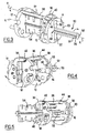
- the Figure 1 illustrates a lock cylinder according to a preferred embodiment of the invention, it comprises two facing disks, an input disk 10 and an output disk 12 forming flanges, the disks 10, 12 being held together by rods of link 14, so as to form a central passageway of longitudinal axis X.
- the input disk 10 has an inlet slot 16 which extends transversely along a diameter of the input disk 10, while the disk outlet 12 has an exit slot 18 oriented perpendicular to the inlet slit 16.
- the lock cylinder has a sealing washer 20 rotatably mounted facing the inlet disk 10, this washer shutter 20 also having a slot 22, said secondary slot, narrower than the entrance slot 16, but also long and on the present Figure 1 exactly coincides with this input slot 16.
- the secondary slot 22 has a central portion 24 in which are formed two opposite grooves 26, 28 whose function will be explained hereinafter.
- the sealing washer 20 has a circular outer peripheral edge 30 masked on the Figure 1 by a shoulder, and which has a stop tooth 32 backed to the shoulder.
- the stop tooth 32 has a bearing surface 33.
- the cylinder comprises a key 34 comprising a drive shaft 36 of axis A, which drive shaft 36 comprises a perpendicular actuating lever 37 whose function will be explained in the following description, and an end 38.
- a notch forming a flat portion 40, said flat being, on the Figure 1 extended to the bearing surface 33 of the stop tooth 32.
- the surface of said flat 40 is substantially spaced from the bearing surface 33, however in reality these two surfaces are close together. from one another to allow proper operation.
- the drive shaft 36 is mounted in two opposite notches, a first notch 42 formed in the output disk 12 and a second 44, formed in the input disk 10, these notches 42, 44 then forming bearings for allow the rotational guidance of the drive shaft 36.
- the flat 40 has an eccentric free edge 46 with respect to the axis of rotation A of the drive shaft 36.
- the drive shaft 36 can not be rotated because otherwise this eccentric free edge 46 abuts against the bearing surface 33.
- FIG. 2 illustrates in a rear view the cylinder shown in Figure 1 . It contains the input disk 10 and its transverse entrance slot 16 which unlike the central portion 24 of the secondary form 22 of the sealing washer 20 has an enlarged central portion 47 of circular symmetry. There is also found, the output disc 12 and the key 34, a portion 48 forming platinum, extends opposite an outlet face 49 by closing the exit slot 18, and the drive shaft 36 which extends, from one disc to the other through the two notches 42 and 44.
- the platinum portion 48 of the key 34 is substantially perpendicular to the drive shaft 36 and is adapted to pivot in the direction clockwise, here in rear view, substantially parallel to the output disk 12 facing the output face 49, when the drive shaft 36 is rotated in the same direction.
- the eccentric free edge 46 and the bearing surface 33 which are here masked by the input disk 10 are adapted to cooperate to lock the drive shaft 36 in rotation at least in the direction of clockwise and thus prohibit the pivoting of the portion 48 forming the plate of the key 34. Therefore, even if a tool would be introduced through the secondary slot 22 and the entry slot 16, in order to rotate the platinum portion 48 through the exit slot 18, it could not do so without resistance, since the drive shaft 36 secured to the portion 48, is blocked.
- the rod 52 has a non-circular cross section, in cross, said rod having two opposite longitudinal ribs 56, 58 which extend on either side of the rod 52.
- the key 50 is then adapted to be introduced through the secondary slot 22, the rod 52 in the central portion 24 so that the two opposite ribs 52, 58 penetrate into the respective ribs 28, 26.
- the rod 52 is connected in rotation with the sealing washer 20 while it is not with the input disk 10 since the slot 16 has a central portion 47 of circular symmetry which is masked on this Figure by the sealing washer 20.
- the rod 52 is free in rotation in the entrance slit 16.
- the flat 40 is then sufficiently distant from the circular outer circumferential edge 30 to allow the eccentric free edge 46 to pivot towards this peripheral edge 30 and consequently the rotation of the drive shaft 36.
- the key 50 can then be driven in translation, so as to drive the bit 54 through the exit slot 18 and thus go to join the lock mechanism, which is likely to be actuated him also by the rotation of the bit 54.
Landscapes
- Lock And Its Accessories (AREA)
- Chairs Characterized By Structure (AREA)
- Mutual Connection Of Rods And Tubes (AREA)
- Fluid-Damping Devices (AREA)
- Display Devices Of Pinball Game Machines (AREA)
- Preventing Unauthorised Actuation Of Valves (AREA)
Claims (10)
- Schlosszylinder, der dazu bestimmt ist, den Durchtritt eines Schlüssels (50) zuzulassen, der einen Halm (52) mit nicht kreisförmigem Querschnitt und einen Bart (54) aufweist, wobei der Schlosszylinder einen Eintrittsschlitz (16) und einen Austrittsschlitz (18) aufweist, wobei der Zylinder mindestens einen Keil (34) umfasst, mit dem der Austrittsschlitz (18) verschlossen gehalten werden kann, wobei der Keil eine Drehantriebswelle (36) aufweist, die angepasst ist, um vom Bart (54) angetrieben zu werden, damit die Freigabe des Austrittsschlitzes (18) erwirkt wird, wobei der Zylinder des Weiteren eine Verschlussscheibe (20) umfasst, die drehbar gegenüber dem Eintrittsschlitz (16) befestigt ist, wobei die Verschlussscheibe einen Nebenschlitz (22) aufweist, wobei der Nebenschlitz einen Mittelbereich (24) aufweist, durch den der Halm (52) in Eingriff kommen soll, wobei die Verschlussscheibe (20) zwischen einer Öffnungsposition, in der sich der Nebenschlitz (22) mit dem Eintrittsschlitz (16) deckt, um den Eintritt des Bartes (54) in den Zylinder zuzulassen, und einer Schließposition beweglich ist, in der der Eintritts- und der Nebenschlitz (16, 22) zueinander winkelversetzt sind und wo die Verschlussscheibe (20) den Eintrittsschlitz (16) zumindest teilweise verschließt, nachdem der Schlüssel (50) in Drehung versetzt wurde, dadurch gekennzeichnet, dass die Verschlussscheibe (20) Sperrmittel (30, 32, 33) aufweist, um die Antriebswelle (36) drehzusperren, wenn sich die Verschlussscheibe (20) in der Öffnungsposition befindet, sodass die Freigabe des Austrittsschlitzes (18) verhindert wird.
- Schlosszylinder nach Anspruch 1, dadurch gekennzeichnet, dass die Antriebswelle (36) ein außermittiges, freies Ende (46) aufweist, das sich im rechten Winkel zur Verschlussscheibe (20) erstreckt, wobei das außermittige, freie Ende (46) angepasst ist, um zur Verschlussscheibe (20) hin zu schwenken, wenn die Antriebswelle (36) in Drehung versetzt wird.
- Schlosszylinder nach Anspruch 2, dadurch gekennzeichnet, dass das außermittige, freie Ende (46) durch Ausführen eines Einschnittes in das Ende (38) der Antriebswelle (36) gebildet wird, wobei der Einschnitt im Wesentlichen eine Abflachung (40) bildet.
- Schlosszylinder nach einem der Ansprüche 1 bis 3, dadurch gekennzeichnet, dass die Verschlussscheibe (20) einen kreisförmigen, äußeren, peripheren Rand (30) aufweist, wobei der kreisförmige, äußere, periphere Rand einen Anschlagzahn (32) umfasst, der die Sperrmittel bildet.
- Schlosszylinder nach Anspruch 3 und 4, dadurch gekennzeichnet, dass der Anschlagzahn (32) eine Auflagefläche (33) aufweist, die dazu bestimmt ist, gegenüber der Abflachung (40) in eine angenäherte Position zu treten, wobei die Auflagefläche (33) und die Abflachung (40) im Wesentlichen parallel sind.
- Schlosszylinder nach einem der Ansprüche 1 bis 5, dadurch gekennzeichnet, dass er zwei Scheiben (10, 12) umfasst, die voneinander beabstandet sind, eine Eintrittsscheibe (10), in der der Eintrittsschlitz (16) ausgebildet ist, und eine Austrittsseheibe (12), in der der Austrittsschlitz (18) ausgebildet ist, wobei die Scheiben zwei gegenüber liegende, periphere Einkerbungen (42, 44) aufweisen, die angepasst sind, um die Drehantriebswelle (36) aufzunehmen.
- Schlosszylinder nach einem der Ansprüche 1 bis 6, dadurch gekennzeichnet, dass der Eintrittsschlitz (16) und der Austrittsschlitz (18) im Wesentlichen um 90° winkelversetzt sind.
- Schlosszylinder nach einem der Ansprüche 1 bis 7, dadurch gekennzeichnet, dass der Keil (34) angepasst ist, um den Austrittsschlitz (18) zu verdecken, um den Durchtritt des Bartes (54) zu verhindern.
- Schlosszylinder nach einem der Ansprüche 1 bis 8, dadurch gekennzeichnet, dass er zwei Sperrkeile umfasst.
- Schloss, das mit einem Schlosszylinder nach einem der Ansprüche 1 bis 9 ausgestattet ist.
Priority Applications (2)
| Application Number | Priority Date | Filing Date | Title |
|---|---|---|---|
| PL06290050T PL1681411T3 (pl) | 2005-01-12 | 2006-01-09 | Cylinder zamka do klucza z trzonem o niekołowym przekroju |
| SI200630568T SI1681411T1 (sl) | 2005-01-12 | 2006-01-09 | Cilinder kljuŽŤavnice za kljuŽŤ, ki ni kroĹľnega prereza |
Applications Claiming Priority (1)
| Application Number | Priority Date | Filing Date | Title |
|---|---|---|---|
| FR0500321A FR2880646B1 (fr) | 2005-01-12 | 2005-01-12 | Cylindre de serrure pour cle a tige de section non circulaire |
Publications (2)
| Publication Number | Publication Date |
|---|---|
| EP1681411A1 EP1681411A1 (de) | 2006-07-19 |
| EP1681411B1 true EP1681411B1 (de) | 2009-12-09 |
Family
ID=34981709
Family Applications (1)
| Application Number | Title | Priority Date | Filing Date |
|---|---|---|---|
| EP06290050A Active EP1681411B1 (de) | 2005-01-12 | 2006-01-09 | Schlosszylinder für Schlüssel mit nicht kreisförmigem Querschnitt |
Country Status (7)
| Country | Link |
|---|---|
| EP (1) | EP1681411B1 (de) |
| AT (1) | ATE451520T1 (de) |
| DE (1) | DE602006010917D1 (de) |
| ES (1) | ES2338037T3 (de) |
| FR (1) | FR2880646B1 (de) |
| PL (1) | PL1681411T3 (de) |
| SI (1) | SI1681411T1 (de) |
Families Citing this family (5)
| Publication number | Priority date | Publication date | Assignee | Title |
|---|---|---|---|---|
| FR2911358B3 (fr) * | 2007-01-12 | 2008-12-12 | Manuf D App Electr De Cahors S | Dispositif de serrure et cle pour boitiers electriques ou electroniques. |
| FR2926315B1 (fr) | 2008-01-11 | 2010-01-22 | Deny Fontaine | Serrure a cylindre comprenant un ensemble cylindrique de rondelles codees |
| FR3002572B1 (fr) * | 2013-02-27 | 2017-12-22 | Deny Fontaine | Cylindre de serrure a cle de chantier |
| FR3048990B1 (fr) * | 2016-03-15 | 2018-03-30 | Deny Security | Cylindre de serrure a filtre securise |
| FR3081177B1 (fr) | 2018-05-18 | 2020-05-29 | Deny Security | Ensemble de commande de verrouillage a cle |
Family Cites Families (5)
| Publication number | Priority date | Publication date | Assignee | Title |
|---|---|---|---|---|
| DE524308C (de) * | 1928-10-26 | 1931-05-06 | Hermann Kade | Schluessellochverschluss |
| DE612259C (de) * | 1933-01-20 | 1935-04-16 | Arthur Stadie | Siecherheitsschloss mit drei hintereinanderliegenden Schluesselloechern |
| FR2641023B1 (de) * | 1988-12-27 | 1991-05-24 | Deny | |
| FR2734858B1 (fr) * | 1995-06-02 | 1997-07-25 | Deny | Procede d'ouverture d'un cylindre de serrure a clavettes pivotantes d'obturation du passage de cle, cylindre et cle pour la mise en oeuvre de ce procede |
| FR2757557B1 (fr) * | 1996-12-24 | 1999-02-19 | Deny | Serrure de surete |
-
2005
- 2005-01-12 FR FR0500321A patent/FR2880646B1/fr not_active Expired - Fee Related
-
2006
- 2006-01-09 AT AT06290050T patent/ATE451520T1/de not_active IP Right Cessation
- 2006-01-09 EP EP06290050A patent/EP1681411B1/de active Active
- 2006-01-09 SI SI200630568T patent/SI1681411T1/sl unknown
- 2006-01-09 PL PL06290050T patent/PL1681411T3/pl unknown
- 2006-01-09 ES ES06290050T patent/ES2338037T3/es active Active
- 2006-01-09 DE DE602006010917T patent/DE602006010917D1/de active Active
Also Published As
| Publication number | Publication date |
|---|---|
| FR2880646B1 (fr) | 2007-04-06 |
| ATE451520T1 (de) | 2009-12-15 |
| EP1681411A1 (de) | 2006-07-19 |
| SI1681411T1 (sl) | 2010-04-30 |
| ES2338037T3 (es) | 2010-05-03 |
| FR2880646A1 (fr) | 2006-07-14 |
| PL1681411T3 (pl) | 2010-05-31 |
| DE602006010917D1 (de) | 2010-01-21 |
Similar Documents
| Publication | Publication Date | Title |
|---|---|---|
| EP1164251B1 (de) | Schloss zur Sicherung von Laufschaufeln | |
| EP1681411B1 (de) | Schlosszylinder für Schlüssel mit nicht kreisförmigem Querschnitt | |
| EP1734552B1 (de) | Betätigungseinrichtung eines elektrischen Schaltgeräts mit Drehsperre | |
| EP2220665B1 (de) | Zweitdeckel für elektrische vorrichtung mit gegossenem gehäuse | |
| EP1291478B1 (de) | Schloss mit Universalaufstellung | |
| EP2078806B1 (de) | Schliesszylinder mit zylindrischer Zuhaltescheibenanordnung | |
| EP3219881B1 (de) | Schliesszylinder mit gesichertem filter | |
| EP3569799B1 (de) | Schliessbetätigungszusammenbau mit schlüssel | |
| FR2871497A1 (fr) | Cle de securite pour cylindre de serrure | |
| EP3597842B1 (de) | Sicherheitsschloss mit codiertem schlüssel | |
| OA19293A (en) | Ensemble de commande de verrouillage à clé. | |
| FR2802234A1 (fr) | Barillet de surete muni d'un moyen anti-crochetage | |
| FR2802233A1 (fr) | Barillet de surete muni d'un moyen anti-vibreur | |
| FR2775716A1 (fr) | Cylindre de surete a barillet double | |
| OA18189A (fr) | Cylindre de serrure à filtre sécurisé | |
| OA19144A (en) | Serrure de sûreté à clé codée. | |
| EP2772602A1 (de) | Zylinderschloss für Bauschlüssel | |
| FR2915122A1 (fr) | Outil de vissage comprenant une fenetre de reglage d'un couple de vissage et une trappe d'obturation de la fenetre susceptible d'etre entrainee par un mecanisme presentant des moyens d'actionnement | |
| EP3005390B1 (de) | Vorrichtung zur steuerung eines elektrischen geräts mit axial verlaufenden kerben | |
| EP2653637A1 (de) | Einstellbares Einsteckschloss mit schmalem Profil | |
| EP2594817B1 (de) | Vorrichtung zur axialen Positionierung einer Pleuelstange bezüglich ihrer Antriebswelle, und Sicherheitszuhaltung der Tür in einer Zelle, die eine solche Vorrichtung umfasst | |
| FR3001486A1 (fr) | Systeme de serrure a cle du type tubulaire. | |
| FR2907354A1 (fr) | Mandrin porte-outil pour l'equipement d'une machine tournante | |
| FR2910517A1 (fr) | Serrure a barillet de securite. | |
| FR2913711A1 (fr) | Serrure a penes multiples |
Legal Events
| Date | Code | Title | Description |
|---|---|---|---|
| PUAI | Public reference made under article 153(3) epc to a published international application that has entered the european phase |
Free format text: ORIGINAL CODE: 0009012 |
|
| AK | Designated contracting states |
Kind code of ref document: A1 Designated state(s): AT BE BG CH CY CZ DE DK EE ES FI FR GB GR HU IE IS IT LI LT LU LV MC NL PL PT RO SE SI SK TR |
|
| AX | Request for extension of the european patent |
Extension state: AL BA HR MK YU |
|
| 17P | Request for examination filed |
Effective date: 20070119 |
|
| AKX | Designation fees paid |
Designated state(s): AT BE BG CH CY CZ DE DK EE ES FI FR GB GR HU IE IS IT LI LT LU LV MC NL PL PT RO SE SI SK TR |
|
| GRAP | Despatch of communication of intention to grant a patent |
Free format text: ORIGINAL CODE: EPIDOSNIGR1 |
|
| GRAS | Grant fee paid |
Free format text: ORIGINAL CODE: EPIDOSNIGR3 |
|
| GRAA | (expected) grant |
Free format text: ORIGINAL CODE: 0009210 |
|
| AK | Designated contracting states |
Kind code of ref document: B1 Designated state(s): AT BE BG CH CY CZ DE DK EE ES FI FR GB GR HU IE IS IT LI LT LU LV MC NL PL PT RO SE SI SK TR |
|
| REG | Reference to a national code |
Ref country code: GB Ref legal event code: FG4D Free format text: NOT ENGLISH |
|
| REG | Reference to a national code |
Ref country code: CH Ref legal event code: EP |
|
| REG | Reference to a national code |
Ref country code: IE Ref legal event code: FG4D |
|
| REF | Corresponds to: |
Ref document number: 602006010917 Country of ref document: DE Date of ref document: 20100121 Kind code of ref document: P |
|
| REG | Reference to a national code |
Ref country code: RO Ref legal event code: EPE |
|
| REG | Reference to a national code |
Ref country code: NL Ref legal event code: VDEP Effective date: 20091209 |
|
| PG25 | Lapsed in a contracting state [announced via postgrant information from national office to epo] |
Ref country code: FI Free format text: LAPSE BECAUSE OF FAILURE TO SUBMIT A TRANSLATION OF THE DESCRIPTION OR TO PAY THE FEE WITHIN THE PRESCRIBED TIME-LIMIT Effective date: 20091209 Ref country code: SE Free format text: LAPSE BECAUSE OF FAILURE TO SUBMIT A TRANSLATION OF THE DESCRIPTION OR TO PAY THE FEE WITHIN THE PRESCRIBED TIME-LIMIT Effective date: 20091209 Ref country code: LT Free format text: LAPSE BECAUSE OF FAILURE TO SUBMIT A TRANSLATION OF THE DESCRIPTION OR TO PAY THE FEE WITHIN THE PRESCRIBED TIME-LIMIT Effective date: 20091209 |
|
| REG | Reference to a national code |
Ref country code: ES Ref legal event code: FG2A Ref document number: 2338037 Country of ref document: ES Kind code of ref document: T3 |
|
| LTIE | Lt: invalidation of european patent or patent extension |
Effective date: 20091209 |
|
| PG25 | Lapsed in a contracting state [announced via postgrant information from national office to epo] |
Ref country code: LV Free format text: LAPSE BECAUSE OF FAILURE TO SUBMIT A TRANSLATION OF THE DESCRIPTION OR TO PAY THE FEE WITHIN THE PRESCRIBED TIME-LIMIT Effective date: 20091209 |
|
| REG | Reference to a national code |
Ref country code: PL Ref legal event code: T3 |
|
| REG | Reference to a national code |
Ref country code: SK Ref legal event code: T3 Ref document number: E 6903 Country of ref document: SK |
|
| PG25 | Lapsed in a contracting state [announced via postgrant information from national office to epo] |
Ref country code: AT Free format text: LAPSE BECAUSE OF FAILURE TO SUBMIT A TRANSLATION OF THE DESCRIPTION OR TO PAY THE FEE WITHIN THE PRESCRIBED TIME-LIMIT Effective date: 20091209 |
|
| REG | Reference to a national code |
Ref country code: IE Ref legal event code: FD4D |
|
| REG | Reference to a national code |
Ref country code: HU Ref legal event code: AG4A Ref document number: E007537 Country of ref document: HU |
|
| PG25 | Lapsed in a contracting state [announced via postgrant information from national office to epo] |
Ref country code: IS Free format text: LAPSE BECAUSE OF FAILURE TO SUBMIT A TRANSLATION OF THE DESCRIPTION OR TO PAY THE FEE WITHIN THE PRESCRIBED TIME-LIMIT Effective date: 20100409 Ref country code: BG Free format text: LAPSE BECAUSE OF FAILURE TO SUBMIT A TRANSLATION OF THE DESCRIPTION OR TO PAY THE FEE WITHIN THE PRESCRIBED TIME-LIMIT Effective date: 20100309 Ref country code: PT Free format text: LAPSE BECAUSE OF FAILURE TO SUBMIT A TRANSLATION OF THE DESCRIPTION OR TO PAY THE FEE WITHIN THE PRESCRIBED TIME-LIMIT Effective date: 20100409 Ref country code: IE Free format text: LAPSE BECAUSE OF FAILURE TO SUBMIT A TRANSLATION OF THE DESCRIPTION OR TO PAY THE FEE WITHIN THE PRESCRIBED TIME-LIMIT Effective date: 20091209 Ref country code: EE Free format text: LAPSE BECAUSE OF FAILURE TO SUBMIT A TRANSLATION OF THE DESCRIPTION OR TO PAY THE FEE WITHIN THE PRESCRIBED TIME-LIMIT Effective date: 20091209 Ref country code: NL Free format text: LAPSE BECAUSE OF FAILURE TO SUBMIT A TRANSLATION OF THE DESCRIPTION OR TO PAY THE FEE WITHIN THE PRESCRIBED TIME-LIMIT Effective date: 20091209 |
|
| PG25 | Lapsed in a contracting state [announced via postgrant information from national office to epo] |
Ref country code: MC Free format text: LAPSE BECAUSE OF NON-PAYMENT OF DUE FEES Effective date: 20100131 |
|
| PLBE | No opposition filed within time limit |
Free format text: ORIGINAL CODE: 0009261 |
|
| STAA | Information on the status of an ep patent application or granted ep patent |
Free format text: STATUS: NO OPPOSITION FILED WITHIN TIME LIMIT |
|
| PG25 | Lapsed in a contracting state [announced via postgrant information from national office to epo] |
Ref country code: CY Free format text: LAPSE BECAUSE OF FAILURE TO SUBMIT A TRANSLATION OF THE DESCRIPTION OR TO PAY THE FEE WITHIN THE PRESCRIBED TIME-LIMIT Effective date: 20091209 Ref country code: GR Free format text: LAPSE BECAUSE OF FAILURE TO SUBMIT A TRANSLATION OF THE DESCRIPTION OR TO PAY THE FEE WITHIN THE PRESCRIBED TIME-LIMIT Effective date: 20100310 |
|
| 26N | No opposition filed |
Effective date: 20100910 |
|
| PG25 | Lapsed in a contracting state [announced via postgrant information from national office to epo] |
Ref country code: DK Free format text: LAPSE BECAUSE OF FAILURE TO SUBMIT A TRANSLATION OF THE DESCRIPTION OR TO PAY THE FEE WITHIN THE PRESCRIBED TIME-LIMIT Effective date: 20091209 |
|
| PG25 | Lapsed in a contracting state [announced via postgrant information from national office to epo] |
Ref country code: LU Free format text: LAPSE BECAUSE OF NON-PAYMENT OF DUE FEES Effective date: 20100109 |
|
| PG25 | Lapsed in a contracting state [announced via postgrant information from national office to epo] |
Ref country code: TR Free format text: LAPSE BECAUSE OF FAILURE TO SUBMIT A TRANSLATION OF THE DESCRIPTION OR TO PAY THE FEE WITHIN THE PRESCRIBED TIME-LIMIT Effective date: 20091209 |
|
| REG | Reference to a national code |
Ref country code: FR Ref legal event code: PLFP Year of fee payment: 11 |
|
| REG | Reference to a national code |
Ref country code: FR Ref legal event code: CD Owner name: DENY SECURITY, FR Effective date: 20160404 |
|
| REG | Reference to a national code |
Ref country code: FR Ref legal event code: PLFP Year of fee payment: 12 |
|
| REG | Reference to a national code |
Ref country code: FR Ref legal event code: PLFP Year of fee payment: 13 |
|
| PGFP | Annual fee paid to national office [announced via postgrant information from national office to epo] |
Ref country code: FR Payment date: 20230117 Year of fee payment: 18 |
|
| PGFP | Annual fee paid to national office [announced via postgrant information from national office to epo] |
Ref country code: IT Payment date: 20230120 Year of fee payment: 18 Ref country code: BE Payment date: 20230119 Year of fee payment: 18 |
|
| P01 | Opt-out of the competence of the unified patent court (upc) registered |
Effective date: 20230628 |
|
| PGFP | Annual fee paid to national office [announced via postgrant information from national office to epo] |
Ref country code: RO Payment date: 20231228 Year of fee payment: 19 |
|
| PGFP | Annual fee paid to national office [announced via postgrant information from national office to epo] |
Ref country code: PL Payment date: 20231229 Year of fee payment: 19 |
|
| PGFP | Annual fee paid to national office [announced via postgrant information from national office to epo] |
Ref country code: ES Payment date: 20240223 Year of fee payment: 19 |
|
| PGFP | Annual fee paid to national office [announced via postgrant information from national office to epo] |
Ref country code: HU Payment date: 20240123 Year of fee payment: 19 Ref country code: DE Payment date: 20240119 Year of fee payment: 19 Ref country code: CZ Payment date: 20231229 Year of fee payment: 19 Ref country code: GB Payment date: 20240123 Year of fee payment: 19 Ref country code: CH Payment date: 20240202 Year of fee payment: 19 Ref country code: SK Payment date: 20240104 Year of fee payment: 19 |
|
| PGFP | Annual fee paid to national office [announced via postgrant information from national office to epo] |
Ref country code: SI Payment date: 20231228 Year of fee payment: 19 |