EP1678771B1 - Batterie a poche - Google Patents
Batterie a poche Download PDFInfo
- Publication number
- EP1678771B1 EP1678771B1 EP04768914A EP04768914A EP1678771B1 EP 1678771 B1 EP1678771 B1 EP 1678771B1 EP 04768914 A EP04768914 A EP 04768914A EP 04768914 A EP04768914 A EP 04768914A EP 1678771 B1 EP1678771 B1 EP 1678771B1
- Authority
- EP
- European Patent Office
- Prior art keywords
- anode
- cathode
- pouch battery
- battery according
- sheet
- Prior art date
- Legal status (The legal status is an assumption and is not a legal conclusion. Google has not performed a legal analysis and makes no representation as to the accuracy of the status listed.)
- Active
Links
- 229910052744 lithium Inorganic materials 0.000 claims abstract description 40
- WHXSMMKQMYFTQS-UHFFFAOYSA-N Lithium Chemical compound [Li] WHXSMMKQMYFTQS-UHFFFAOYSA-N 0.000 claims abstract description 37
- 239000010410 layer Substances 0.000 claims description 33
- 239000003792 electrolyte Substances 0.000 claims description 14
- 239000010406 cathode material Substances 0.000 claims description 12
- 239000011888 foil Substances 0.000 claims description 12
- 238000000034 method Methods 0.000 claims description 12
- OKTJSMMVPCPJKN-UHFFFAOYSA-N Carbon Chemical compound [C] OKTJSMMVPCPJKN-UHFFFAOYSA-N 0.000 claims description 8
- 239000010405 anode material Substances 0.000 claims description 8
- 229910052799 carbon Inorganic materials 0.000 claims description 8
- 238000011049 filling Methods 0.000 claims description 6
- 239000002356 single layer Substances 0.000 claims description 4
- 238000007789 sealing Methods 0.000 claims description 3
- 239000007787 solid Substances 0.000 claims description 3
- 238000011068 loading method Methods 0.000 claims description 2
- 238000004519 manufacturing process Methods 0.000 claims description 2
- 238000010276 construction Methods 0.000 abstract description 8
- 239000011244 liquid electrolyte Substances 0.000 description 9
- 239000010949 copper Substances 0.000 description 8
- RYGMFSIKBFXOCR-UHFFFAOYSA-N Copper Chemical compound [Cu] RYGMFSIKBFXOCR-UHFFFAOYSA-N 0.000 description 7
- 229910052802 copper Inorganic materials 0.000 description 7
- 238000004806 packaging method and process Methods 0.000 description 7
- 230000008901 benefit Effects 0.000 description 6
- -1 for example Chemical class 0.000 description 6
- 239000012528 membrane Substances 0.000 description 5
- 239000002033 PVDF binder Substances 0.000 description 4
- 239000011248 coating agent Substances 0.000 description 4
- 238000000576 coating method Methods 0.000 description 4
- 238000003780 insertion Methods 0.000 description 4
- 230000037431 insertion Effects 0.000 description 4
- NUJOXMJBOLGQSY-UHFFFAOYSA-N manganese dioxide Chemical compound O=[Mn]=O NUJOXMJBOLGQSY-UHFFFAOYSA-N 0.000 description 4
- 239000000463 material Substances 0.000 description 4
- 239000000203 mixture Substances 0.000 description 4
- 229920002981 polyvinylidene fluoride Polymers 0.000 description 4
- 239000002243 precursor Substances 0.000 description 4
- 229920003182 Surlyn® Polymers 0.000 description 3
- 239000005035 Surlyn® Substances 0.000 description 3
- 229910001496 lithium tetrafluoroborate Inorganic materials 0.000 description 3
- 229920000642 polymer Polymers 0.000 description 3
- BTBUEUYNUDRHOZ-UHFFFAOYSA-N Borate Chemical compound [O-]B([O-])[O-] BTBUEUYNUDRHOZ-UHFFFAOYSA-N 0.000 description 2
- XTHFKEDIFFGKHM-UHFFFAOYSA-N Dimethoxyethane Chemical compound COCCOC XTHFKEDIFFGKHM-UHFFFAOYSA-N 0.000 description 2
- 239000000654 additive Substances 0.000 description 2
- 230000000996 additive effect Effects 0.000 description 2
- 239000005030 aluminium foil Substances 0.000 description 2
- 239000006182 cathode active material Substances 0.000 description 2
- 239000011245 gel electrolyte Substances 0.000 description 2
- 238000011065 in-situ storage Methods 0.000 description 2
- 239000003960 organic solvent Substances 0.000 description 2
- 239000005518 polymer electrolyte Substances 0.000 description 2
- 238000003825 pressing Methods 0.000 description 2
- RUOJZAUFBMNUDX-UHFFFAOYSA-N propylene carbonate Chemical compound CC1COC(=O)O1 RUOJZAUFBMNUDX-UHFFFAOYSA-N 0.000 description 2
- 239000002904 solvent Substances 0.000 description 2
- OIFBSDVPJOWBCH-UHFFFAOYSA-N Diethyl carbonate Chemical compound CCOC(=O)OCC OIFBSDVPJOWBCH-UHFFFAOYSA-N 0.000 description 1
- KMTRUDSVKNLOMY-UHFFFAOYSA-N Ethylene carbonate Chemical compound O=C1OCCO1 KMTRUDSVKNLOMY-UHFFFAOYSA-N 0.000 description 1
- SECXISVLQFMRJM-UHFFFAOYSA-N N-Methylpyrrolidone Chemical compound CN1CCCC1=O SECXISVLQFMRJM-UHFFFAOYSA-N 0.000 description 1
- 239000004743 Polypropylene Substances 0.000 description 1
- 230000001154 acute effect Effects 0.000 description 1
- 229910045601 alloy Inorganic materials 0.000 description 1
- 239000000956 alloy Substances 0.000 description 1
- 230000000712 assembly Effects 0.000 description 1
- 238000000429 assembly Methods 0.000 description 1
- 230000009286 beneficial effect Effects 0.000 description 1
- 239000011230 binding agent Substances 0.000 description 1
- NFMAZVUSKIJEIH-UHFFFAOYSA-N bis(sulfanylidene)iron Chemical compound S=[Fe]=S NFMAZVUSKIJEIH-UHFFFAOYSA-N 0.000 description 1
- 239000006229 carbon black Substances 0.000 description 1
- 230000015556 catabolic process Effects 0.000 description 1
- 229910000428 cobalt oxide Inorganic materials 0.000 description 1
- IVMYJDGYRUAWML-UHFFFAOYSA-N cobalt(ii) oxide Chemical compound [Co]=O IVMYJDGYRUAWML-UHFFFAOYSA-N 0.000 description 1
- 239000002131 composite material Substances 0.000 description 1
- 230000003247 decreasing effect Effects 0.000 description 1
- IEJIGPNLZYLLBP-UHFFFAOYSA-N dimethyl carbonate Chemical compound COC(=O)OC IEJIGPNLZYLLBP-UHFFFAOYSA-N 0.000 description 1
- 238000001035 drying Methods 0.000 description 1
- JBTWLSYIZRCDFO-UHFFFAOYSA-N ethyl methyl carbonate Chemical compound CCOC(=O)OC JBTWLSYIZRCDFO-UHFFFAOYSA-N 0.000 description 1
- 239000010419 fine particle Substances 0.000 description 1
- 238000013467 fragmentation Methods 0.000 description 1
- 238000006062 fragmentation reaction Methods 0.000 description 1
- 238000000227 grinding Methods 0.000 description 1
- MHCFAGZWMAWTNR-UHFFFAOYSA-M lithium perchlorate Chemical compound [Li+].[O-]Cl(=O)(=O)=O MHCFAGZWMAWTNR-UHFFFAOYSA-M 0.000 description 1
- 229910001486 lithium perchlorate Inorganic materials 0.000 description 1
- 229910052751 metal Inorganic materials 0.000 description 1
- 239000002184 metal Substances 0.000 description 1
- 238000002156 mixing Methods 0.000 description 1
- 150000005677 organic carbonates Chemical class 0.000 description 1
- 239000012466 permeate Substances 0.000 description 1
- 229920001155 polypropylene Polymers 0.000 description 1
- 239000002002 slurry Substances 0.000 description 1
- 239000000758 substrate Substances 0.000 description 1
Images


Classifications
-
- H—ELECTRICITY
- H01—ELECTRIC ELEMENTS
- H01M—PROCESSES OR MEANS, e.g. BATTERIES, FOR THE DIRECT CONVERSION OF CHEMICAL ENERGY INTO ELECTRICAL ENERGY
- H01M4/00—Electrodes
- H01M4/02—Electrodes composed of, or comprising, active material
- H01M4/06—Electrodes for primary cells
- H01M4/08—Processes of manufacture
- H01M4/12—Processes of manufacture of consumable metal or alloy electrodes
-
- H—ELECTRICITY
- H01—ELECTRIC ELEMENTS
- H01M—PROCESSES OR MEANS, e.g. BATTERIES, FOR THE DIRECT CONVERSION OF CHEMICAL ENERGY INTO ELECTRICAL ENERGY
- H01M50/00—Constructional details or processes of manufacture of the non-active parts of electrochemical cells other than fuel cells, e.g. hybrid cells
- H01M50/10—Primary casings, jackets or wrappings of a single cell or a single battery
- H01M50/102—Primary casings, jackets or wrappings of a single cell or a single battery characterised by their shape or physical structure
- H01M50/105—Pouches or flexible bags
-
- H—ELECTRICITY
- H01—ELECTRIC ELEMENTS
- H01M—PROCESSES OR MEANS, e.g. BATTERIES, FOR THE DIRECT CONVERSION OF CHEMICAL ENERGY INTO ELECTRICAL ENERGY
- H01M10/00—Secondary cells; Manufacture thereof
- H01M10/04—Construction or manufacture in general
- H01M10/0413—Large-sized flat cells or batteries for motive or stationary systems with plate-like electrodes
-
- H—ELECTRICITY
- H01—ELECTRIC ELEMENTS
- H01M—PROCESSES OR MEANS, e.g. BATTERIES, FOR THE DIRECT CONVERSION OF CHEMICAL ENERGY INTO ELECTRICAL ENERGY
- H01M10/00—Secondary cells; Manufacture thereof
- H01M10/04—Construction or manufacture in general
- H01M10/045—Cells or batteries with folded plate-like electrodes
-
- H—ELECTRICITY
- H01—ELECTRIC ELEMENTS
- H01M—PROCESSES OR MEANS, e.g. BATTERIES, FOR THE DIRECT CONVERSION OF CHEMICAL ENERGY INTO ELECTRICAL ENERGY
- H01M4/00—Electrodes
- H01M4/02—Electrodes composed of, or comprising, active material
- H01M4/13—Electrodes for accumulators with non-aqueous electrolyte, e.g. for lithium-accumulators; Processes of manufacture thereof
-
- H—ELECTRICITY
- H01—ELECTRIC ELEMENTS
- H01M—PROCESSES OR MEANS, e.g. BATTERIES, FOR THE DIRECT CONVERSION OF CHEMICAL ENERGY INTO ELECTRICAL ENERGY
- H01M6/00—Primary cells; Manufacture thereof
- H01M6/04—Cells with aqueous electrolyte
- H01M6/06—Dry cells, i.e. cells wherein the electrolyte is rendered non-fluid
- H01M6/10—Dry cells, i.e. cells wherein the electrolyte is rendered non-fluid with wound or folded electrodes
-
- H—ELECTRICITY
- H01—ELECTRIC ELEMENTS
- H01M—PROCESSES OR MEANS, e.g. BATTERIES, FOR THE DIRECT CONVERSION OF CHEMICAL ENERGY INTO ELECTRICAL ENERGY
- H01M6/00—Primary cells; Manufacture thereof
- H01M6/14—Cells with non-aqueous electrolyte
- H01M6/16—Cells with non-aqueous electrolyte with organic electrolyte
-
- Y—GENERAL TAGGING OF NEW TECHNOLOGICAL DEVELOPMENTS; GENERAL TAGGING OF CROSS-SECTIONAL TECHNOLOGIES SPANNING OVER SEVERAL SECTIONS OF THE IPC; TECHNICAL SUBJECTS COVERED BY FORMER USPC CROSS-REFERENCE ART COLLECTIONS [XRACs] AND DIGESTS
- Y02—TECHNOLOGIES OR APPLICATIONS FOR MITIGATION OR ADAPTATION AGAINST CLIMATE CHANGE
- Y02E—REDUCTION OF GREENHOUSE GAS [GHG] EMISSIONS, RELATED TO ENERGY GENERATION, TRANSMISSION OR DISTRIBUTION
- Y02E60/00—Enabling technologies; Technologies with a potential or indirect contribution to GHG emissions mitigation
- Y02E60/10—Energy storage using batteries
-
- Y—GENERAL TAGGING OF NEW TECHNOLOGICAL DEVELOPMENTS; GENERAL TAGGING OF CROSS-SECTIONAL TECHNOLOGIES SPANNING OVER SEVERAL SECTIONS OF THE IPC; TECHNICAL SUBJECTS COVERED BY FORMER USPC CROSS-REFERENCE ART COLLECTIONS [XRACs] AND DIGESTS
- Y02—TECHNOLOGIES OR APPLICATIONS FOR MITIGATION OR ADAPTATION AGAINST CLIMATE CHANGE
- Y02P—CLIMATE CHANGE MITIGATION TECHNOLOGIES IN THE PRODUCTION OR PROCESSING OF GOODS
- Y02P70/00—Climate change mitigation technologies in the production process for final industrial or consumer products
- Y02P70/50—Manufacturing or production processes characterised by the final manufactured product
Definitions
- the present invention relates to pouch batteries and methods for their construction, and particularly to lithium primary batteries, such as, for example, lithium/carbon monofluoride batteries.
- So-called 'pouch' batteries which are also known as 'envelope' or 'packet' batteries, are increasingly replacing traditional hard-cased batteries in portable electrical applications.
- the battery components are overlaid to form a laminated cell structure, folded to a required size and then packaged in a heat-sealable foil.
- This packaging method offers a light-weight and flexible solution to battery design, and is capable of achieving high energy densities, with the final capacity of the cell being selected according to the desired application.
- Pouch batteries can be based on a variety of different cell chemistries, and a range of electrolyte types can be utilised.
- Lithium primary and secondary batteries for example, are commonly made according to a pouch design, and dry polymer, gel and liquid electrolytes have all been incorporated into pouch cells.
- pouch batteries do not offer optimum conditions for battery safety, particularly when attempts are made to scale them up.
- US 6,190,426 to Dodds et al discloses a prismatic cell comprising an anode-separator-cathode subassembly wound on a mandrel, in which the anode is utilized as a "double-sided" anode with a cathode active layer in face-to-face relationship with each anode surface and with a separator interposed therebetween.
- a pouch battery comprising an electrode assembly, said assembly formed by respectively overlaying a sheet cathode, a sheet separator and a double-sided sheet anode to form a stacked structure, and subjecting the stacked structure to multiple folds, wherein the initial fold comprises folding the cathode in half around the double-sided anode so as to surround the respective upper and lower active anode surfaces thereof.
- the separator lies between the opposing active anode and cathode surfaces so as to prevent contact between the anode and cathode.
- sheet as used herein means "sheet-like", and the separator or electrodes may each be of a single or multiple layer construction, the latter preferably, but not necessarily, being bonded together to form a unitary sheet.
- the anode comprises a single sheet current collector half the size of the cathode (as opposed to a current collector layer the same size as the other sheets, but folded in two); ideally the anode current collector's dimensions should correspond roughly to those of the cathode when folded in half perpendicular to its length.
- the cathode capacity/cm 2 can be reduced, leading to a number of other advantages.
- both the cathode and separator will be substantially the same size and shape, with the anode comprising a current collector layer that is half their size. (In some instances, the separator may be slightly larger than the cathode for safety reasons.) Usually, all three sheets will be of substantially the same width; (again, the separator may be slightly wider for safety reasons).
- the anode will then be laid over the upper half of the length of the other two superimposed sheets, with its bottom edge aligned with the mid-line of the other two sheets.
- the aligned top edges of both anode and cathode electrode sheets have projecting contacts or tabs that act as electrode terminals.
- the cathode is preferably folded midway along its length, so that the fold line extends perpendicular to the sheet length.
- the one or more subsequent folds is then made with the fold line extending perpendicular to the original length of the stacked structure, so that the overall length is halved at each fold and the folds are parallel to one another. (Such aligned half-folds are hereinafter generally referred to as "parallel folds".)
- all the folds in the electrode assembly, including the initial fold are parallel to one another.
- sheet electrodes with appropriately selected widths and lengths are employed to form the stacked structure and then at least two or three folds, up to maximum of about 5 or 6 folds, and preferably up to four folds, are made, as necessary, to reduce the electrode assembly to a convenient size and/or thickness.
- the present invention may be advantageously employed in larger scale pouch cells, that is, cells with nominal capacities exceeding 18Ah, 25Ah, 36Ah or even 50Ah, and also in smaller capacity pouch cells, that is, cells with nominal capacities below 18Ah, 5Ah, 1Ah or even lower.
- electrode sheet widths will usually exceed 5cm and lengths will exceed 1m.
- the present invention relates, in particular, to primary lithium/solid cathode cells and, especially to lithium/carbon monofluoride primary cells.
- the active cathode material is preferably carbon monofluoride, also known as polycarbon monofluoride, or CF x .
- the invention is applicable to all possible cathode materials, such as, for example, manganese dioxide, iron disulphide, or cobalt oxide, and also to secondary, as well as primary, lithium batteries.
- the cathode will normally comprise a sheet current collector and a cathode material layer, and usually the cathode will have an active surface on only one side thereof, over the entire face, formed by the cathode material layer.
- the total cathode and anode capacities will be roughly matched to produce a balanced cell. (A difference in capacities of less than 15% is desirable.) If the cell is not balanced, any excess of either the anode or cathode material will not react and is dead weight. Furthermore, any unconsumed anode material remaining in the cell once the battery has been discharged may pose a safety hazard upon battery disposal, especially for larger scale pouch cells.
- a double-sided anode is one which has two active surfaces, an upper active surface and a lower active surface, usually extending over the entire respective faces.
- the double-sided sheet anode will normally comprise a single sheet current collector and one or more anode material layers forming said upper and lower active surfaces. All the layers may be separate, but are preferably attached together or merged together or otherwise combined together to form a single integral anode.
- the double-sided anode comprises a current collector in the form of a mesh or grid, usually of copper, with lithium foil occupying the openings thereof to form a double-sided lithium anode.
- the double-sided anode may be a single layer of lithium metal having upper and lower active surfaces.
- the loading of the cathode material layer may be selected so that the cathode capacity/cm 2 is about half that of the anode capacity/cm 2 .
- One advantage of having a reduced cathode capacity/cm 2 is that the coating thickness required for the active cathode material is less than it otherwise would be, which gives better coating adhesion, particularly in the case of carbon monofluoride. Furthermore, decreasing the cathode coating thickness leads to a beneficial increase in the power output for the battery.
- a method of manufacturing a pouch battery comprising the steps of:
- the electrode assembly may be placed in a pre-formed envelope that is subsequently sealed at the edge from which the contact tabs protrude, or the pouch may be formed in situ around the electrode assembly.
- the method will include an electrolyte filling stage, prior to the final sealing of the pouch.
- the anode is double-sided, that is to say, both of its surfaces act as effective electrode surfaces.
- the anode will usually include a current collector.
- the current collector may be sandwiched between two separate pieces of lithium foil each backed on to it, or between a single folded piece of lithium foil, advantageously the anode is an integral component comprising lithium foil integrated into a mesh, preferably a copper mesh. This arrangement offers equal amounts of lithium on each side of the anode, while preserving structural integrity and current flow, regardless of the extent of breakdown of the anode.
- a lithium/Cu laminate was formed by pressing 132 micron lithium foil onto 100 micron copper mesh, such that the lithium occupied the spaces within the mesh, to give a composite structure of capacity 27.2 mAh/cm 2 and depth 132 micron. This laminate was then cut to the required size for the anode.
- a pouch battery in which cathode, separator and anode sheets have been respectively overlaid on one another to form a stacked structure, and the structure has been successively folded in half so that its length is halved at each fold, each fold being made upon the same side of the structure with the fold lines extending perpendicular to the original length.
- Elevational and plan views of a typical prior art arrangement used to form an electrode assembly are illustrated in Figures 1a and 1b respectively.
- the prior art assembly comprises a cathode collector layer (1), a cathode material layer (2), a separator (3), an anode material layer (4) and an anode collector layer (5), wherein each layer is substantially the same length and width.
- the collector layers (5) and (1) each comprise an additional tab of collector material (6) and (7) to act as respective anode and cathode terminals.
- the component layers are overlaid and together form a stacked structure that can be folded subsequently, if desired, to a smaller size. As indicated above, fan or zig-zag folds have commonly been used to reduce the size of prior art electrode assemblies prior to insertion into the packaging pouch.
- Figure 2 is an exploded view, illustrating the components of a stacked structure used according to the present invention to form an electrode assembly for a pouch battery.
- Figures 3a and 3b show elevational and plan views, respectively, of the structure, prior to the initial folding step.
- the cathode collector layer (1), cathode material layer (2) and separator (3) are laid up in the same manner as in the prior art arrangement.
- a double-sided anode (9) comprising anode material layers (4) and an anode collector layer (8) is positioned such that the bottom edge of the anode is aligned with a mid-line A-A of the cathode and separator layers.
- the double-sided anode (9) is substantially half the length of the cathode and separator layers.
- Figures 4a and 4b show elevational and plan views, respectively, of the stacked structure after the initial fold.
- the anode collector preferably comprises a metal mesh, grid or gauze, and is used to provide the external anodic, or negative, contact to the cell.
- the anode collector comprises a copper mesh.
- the cathode collector provides the external cathodic, or positive, contact to the cell and preferably comprises aluminium foil. Other suitable collector materials are well known in the art.
- the anode material layers function as the anode of the battery and preferably comprise lithium.
- the anode collector and lithium together form an integral anode, wherein lithium is present on both sides of the anode collector.
- the integral anode is formed by pressing lithium foil onto a mesh, most suitably a copper mesh, such that the lithium occupies the openings of the mesh.
- the purpose of the separator is to separate the anode from the cathode, to carry the electrolyte and to act as a safety shut-down separator should the pouch cell overheat.
- the electrolyte may itself function as the separator.
- the separator may comprise a semi-permeable or porous membrane which is soaked with the electrolyte.
- the separator comprises a liquid electrolyte and a semi-permeable membrane.
- the semi-permeable membrane is a tri-layer polymer laminate, for example a polypropylene-polyethylene-polypropylene laminate.
- the liquid electrolyte comprises an organic carbonate, such as, for example, one or more of propylene carbonate, ethylene carbonate, dimethyl carbonate, diethyl carbonate and ethyl methyl carbonate, a borate, such as, for example, lithium bis-oxalato borate and lithium tetrafluoroborate, lithium hexafluorophosphate, lithium hexafluoroarsenate, lithium perchlorate, or any mixture thereof.
- the liquid electrolyte is dispersed in an organic solvent such as, for example, dimethoxyethane.
- the electrode assembly requires one or more further folds, so as to form a compact assembly of the correct size for insertion into the packaging envelope. Any suitable folding method may be used, but preferably the one or more further folds are parallel folds. It is believed that parallel folds cause less damage to the various electrode and separator materials at the folds, thereby improving cell performance.
- the electrolyte filling stage is preferably injected into a semi-permeable separator membrane after the precursor electrode assembly has been folded ready for insertion into the envelope packaging. More preferably, the liquid electrolyte is injected after the precursor electrode assembly has been inserted into the envelope packaging. In either case, the electrolyte needs to permeate the entire length of the separator membrane so as to yield an efficient cell.
- the inventors have found that parallel folds aid this process, leading to more rapid and more complete permeation than for a fan folded assembly. This may be due to less severe folds, but this is merely a theory.
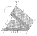
- Figure 5 illustrates the parallel folding process.
- a parallel fold brings the lower edge of the stacked structure (10), indicated as edge B-B in Figure 5 , up to, and parallel with, the upper edge of the stacked structure, indicated as edge C-C in Figure 5 , in the direction indicated by the arrow.
- Contact tabs (6) and (7) are left exposed.
- the fold line, indicated as D-D in Figure 5 is therefore the mid-point of the unfolded stacked structure.
- the fold edge D-D becomes the lower edge of the stacked structure, and so on.
- Successive parallel folds are preferably made on the same side of the stacked structure, (that is, folding continues in the direction of the arrow), which leads to less overall stress on its components.
- up to 5 or 6 folds are required in total. More preferably, up to 4 folds are required.
- the packaging envelope comprises a foil layer, for example Surlyn®, which is folded to the required dimensions and heat sealed, either prior to insertion of the electrode assembly or in situ during construction of the electrode assembly. If an electrolyte-filling step is required, the edge bearing the contact tabs is sealed after said filling step.
- a foil layer for example Surlyn®
- the cathode material is coated onto the cathode collector as a slurry prior to assembling the precursor electrode assembly, thus forming an integral cathode.
- the anode collector and lithium layer also form an integral electrode.
- a 25 Ah primary lithium carbon monofluoride cell was manufactured in the following way:
- a cathode sheet was prepared by, first, grinding and mixing intimately 42g carbon monofluoride and 3.2g of conductivity additive (carbon black).
- a binder solution was prepared by dissolving 4.8g of polyvinylidene fluoride (PVDF) in N-methyl pyrollidinone. Then a paste was formed from the CF x mixture and the PVDF solution.
- PVDF polyvinylidene fluoride
- Aluminium foil (1050 Alloy, 25-30 micron) was cleaned and the cathode paste was coated onto the Al foil to a depth of 570 micron, so as to give a cathode capacity of 12.6 to 13.6 mAh/cm 2 .
- the sheet was then dried to give a final cathode composition by weight of 84:9.6:6.4 w/o CF x :PVDF:conductivity additive, and a final coating thickness of 185 micron.
- the cathode sheet was cut to a length of 208cm and a width of 9cm, leaving an extra length for the terminal.
- the sheets were folded in half and vacuum dried, and, after drying, the cathode sheets were rolled and the cathode electrical terminals were prepared.
- the anode was prepared using a laminate formed from copper mesh and a single layer of lithium foil, the latter attached from one side of the mesh.
- the laminate was cut to a length of 104cm and a width of 9cm, leaving an extra length for the terminal, and then the laminate sheet was rolled.
- the thickness of the copper mesh was 100 micron and the lithium foil thickness was 132 micron, giving an anode capacity of 27.2 mAh/cm 2 .
- the anode electrical terminal was prepared by removing lithium from a defined area of the anode laminate with a suitable solvent. The lithium anode was then dried under vacuum to remove traces of solvent.
- a safety separator (Celgard) was dried overnight under vacuum and then cut to a length of 209.5cm and a width of 10.5cm.
- a Surlyn® sheet was cut and trimmed to the correct dimensions to form the cell packaging, and then heat sealed.
- the cell was fabricated by first assembling the cathode-separator-anode layers. The cathode and separator layers were then folded around the anode, by means of a single parallel fold, to give a stacked structure of width 9cm and length 104cm. Then, three more parallel folds were applied to give a precursor electrode assembly of length 13cm and width 9cm, and the folded electrode assembly was inserted into the Surlyn® bag.
- the achieved capacity was 24.3 Ah
- the cell utilisation was 95%
- the energy density was 500 Wh/kg.
Landscapes
- Chemical & Material Sciences (AREA)
- Chemical Kinetics & Catalysis (AREA)
- Electrochemistry (AREA)
- General Chemical & Material Sciences (AREA)
- Engineering & Computer Science (AREA)
- Manufacturing & Machinery (AREA)
- Materials Engineering (AREA)
- Battery Electrode And Active Subsutance (AREA)
- Secondary Cells (AREA)
- Primary Cells (AREA)
- Air Bags (AREA)
- Sealing Battery Cases Or Jackets (AREA)
- Cell Electrode Carriers And Collectors (AREA)
- Cell Separators (AREA)
Claims (22)
- Batterie à poche comprenant un assemblage d'électrodes, ledit assemblage étant formé par la superposition respective d'une feuille de cathode, d'une feuille de séparateur et d'une feuille d'anode double face pour former une structure empilée, et par des pliages multiples de la structure empilée, dans laquelle le pliage initial consiste à plier la cathode en deux autour de l'anode double face de sorte qu'elle entoure les surfaces actives supérieure et inférieure respectives de celle-ci.
- Batterie à poche selon la revendication 1, dans laquelle l'anode comprend une feuille simple collectrice de courant dont les dimensions correspondent à celles de la cathode pliée en deux.
- Batterie à poche selon la revendication 2, dans laquelle la cathode et le séparateur ont une taille et une forme sensiblement identiques.
- Batterie à poche selon l'une quelconque des revendications précédentes, dans laquelle pendant le pliage initial, la cathode est pliée à la moitié de sa longueur de sorte que la ligne de pliage s'étend perpendiculairement à sa longueur.
- Batterie à poche selon l'une quelconque des revendications précédentes, dans laquelle un ou plusieurs plis successifs sont réalisés avec la ligne de pliage s'étendant perpendiculairement à la longueur initiale de la structure empilée et sa longueur totale est divisée par deux à chaque pliage.
- Batterie à poche selon la revendication 5, dans laquelle lesdits un ou plusieurs plis successifs sont réalisés sur le même côté de la structure empilée.
- Batterie à poche selon l'une quelconque des revendications précédentes, dans laquelle jusqu'à 5 ou 6 plis sont réalisés au total.
- Batterie à poche selon l'une quelconque des revendications précédentes, dans laquelle la capacité de la batterie est supérieure à 18 Ah.
- Batterie à poche selon l'une quelconque des revendications précédentes, dans laquelle la cathode comprend une feuille collectrice de courant et une couche de matériau de cathode.
- Batterie à poche selon la revendication 9, dans laquelle la cathode comporte une surface active uniquement sur un côté de celle-ci, formée par la couche de matériau de cathode.
- Batterie à poche selon l'une quelconque des revendications précédentes, dans laquelle les capacités totales de la cathode et de l'anode sont à peu près équivalentes pour produire une cellule équilibrée.
- Batterie à poche selon l'une quelconque des revendications précédentes, qui comprend une cellule primaire lithium/cathode solide.
- Batterie à poche selon l'une quelconque des revendications précédentes, dans laquelle la cathode comprend du monofluorure de carbone.
- Batterie à poche selon l'une quelconque des revendications précédentes, dans laquelle l'anode double face comprend une feuille simple collectrice de courant et une ou plusieurs couches de matériau d'anode formant lesdites surfaces actives supérieure et inférieure.
- Batterie à poche selon la revendication 14, dans laquelle lesdites couches ont été fixées entre elles ou fusionnées entre elles ou autrement associées les unes aux autres pour former une seule anode monobloc.
- Batterie à poche selon la revendication 15, dans laquelle l'anode double face comprend un collecteur de courant sous forme de maillage ou de grille, une feuille de lithium occupant les ouvertures de celui-ci pour former une anode au lithium double face.
- Batterie à poche selon l'une quelconque des revendications 14 à 16, dans laquelle il n'y a qu'une couche de matériau d'anode, qui constitue de manière efficace une seule couche de lithium métallique comportant des surfaces actives supérieure et inférieure.
- Batterie à poche selon l'une quelconque des revendications 14 à 17, dans laquelle la charge de la couche de matériau de cathode est choisie de sorte que la capacité par cm2 de la cathode soit à peu près la moitié de la capacité par cm2 de l'anode.
- Procédé de fabrication d'une batterie à poche, comprenant les étapes consistant à :superposer respectivement une feuille de cathode, une feuille de séparateur et une feuille d'anode double face pour former une structure empilée ;plier la cathode en deux autour de l'anode double face de sorte qu'elle entoure les surfaces actives supérieure et inférieure respectives de celle-ci ;soumettre les feuilles pliées à un ou plusieurs autres pliages pour former un assemblage d'électrodes ; etformer une batterie à poche en enfermant hermétiquement l'assemblage d'électrodes dans une enveloppe.
- Procédé selon la revendication 19, comprenant en outre une étape de remplissage d'électrolyte.
- Procédé selon la revendication 19 ou la revendication 20, dans lequel la batterie à poche est telle que spécifiée dans l'une quelconque des revendications 2 à 18.
- Batterie à poche selon l'une quelconque des revendications 1 à 18, dans laquelle la feuille de séparateur est pliée en deux autour de l'anode double face.
Applications Claiming Priority (2)
| Application Number | Priority Date | Filing Date | Title |
|---|---|---|---|
| GBGB0324582.6A GB0324582D0 (en) | 2003-10-22 | 2003-10-22 | Pouch battery |
| PCT/GB2004/004384 WO2005045966A1 (fr) | 2003-10-22 | 2004-10-18 | Batterie a poche |
Publications (2)
| Publication Number | Publication Date |
|---|---|
| EP1678771A1 EP1678771A1 (fr) | 2006-07-12 |
| EP1678771B1 true EP1678771B1 (fr) | 2010-09-08 |
Family
ID=29595560
Family Applications (1)
| Application Number | Title | Priority Date | Filing Date |
|---|---|---|---|
| EP04768914A Active EP1678771B1 (fr) | 2003-10-22 | 2004-10-18 | Batterie a poche |
Country Status (6)
| Country | Link |
|---|---|
| EP (1) | EP1678771B1 (fr) |
| JP (1) | JP4842826B2 (fr) |
| AT (1) | ATE480876T1 (fr) |
| DE (1) | DE602004029069D1 (fr) |
| GB (2) | GB0324582D0 (fr) |
| WO (1) | WO2005045966A1 (fr) |
Families Citing this family (3)
| Publication number | Priority date | Publication date | Assignee | Title |
|---|---|---|---|---|
| US7875379B2 (en) * | 2005-07-08 | 2011-01-25 | Greatbatch Ltd. | Electrochemical cell having a pocket separator design |
| US20090136834A1 (en) * | 2007-11-27 | 2009-05-28 | Qinetiq Limited | Method of Constructing an Electrode Assembly |
| GB201609686D0 (en) | 2016-06-02 | 2016-07-20 | Qinetiq Ltd | Devices |
Citations (1)
| Publication number | Priority date | Publication date | Assignee | Title |
|---|---|---|---|---|
| US6287721B1 (en) * | 1998-09-24 | 2001-09-11 | Thomas & Betts International, Inc. | Process for manufacturing electrochemical cells |
Family Cites Families (5)
| Publication number | Priority date | Publication date | Assignee | Title |
|---|---|---|---|---|
| JPH09102302A (ja) * | 1995-10-04 | 1997-04-15 | Yuasa Corp | 電池用電極、電池用電極の製造方法および電池 |
| JP3658816B2 (ja) * | 1995-10-24 | 2005-06-08 | 株式会社ユアサコーポレーション | 電極群、電極群の製造装置および電極群の製造方法 |
| JPH11121016A (ja) * | 1997-10-09 | 1999-04-30 | Yuasa Corp | 電 池 |
| US6190426B1 (en) * | 1998-12-17 | 2001-02-20 | Moltech Corporation | Methods of preparing prismatic cells |
| US6923837B2 (en) * | 2002-02-26 | 2005-08-02 | Lithium Power Technologies, Inc. | Consecutively wound or stacked battery cells |
-
2003
- 2003-10-22 GB GBGB0324582.6A patent/GB0324582D0/en not_active Ceased
-
2004
- 2004-10-18 GB GB0608569A patent/GB2422481B8/en active Active
- 2004-10-18 DE DE602004029069T patent/DE602004029069D1/de active Active
- 2004-10-18 WO PCT/GB2004/004384 patent/WO2005045966A1/fr active Application Filing
- 2004-10-18 JP JP2006536155A patent/JP4842826B2/ja active Active
- 2004-10-18 AT AT04768914T patent/ATE480876T1/de not_active IP Right Cessation
- 2004-10-18 EP EP04768914A patent/EP1678771B1/fr active Active
Patent Citations (1)
| Publication number | Priority date | Publication date | Assignee | Title |
|---|---|---|---|---|
| US6287721B1 (en) * | 1998-09-24 | 2001-09-11 | Thomas & Betts International, Inc. | Process for manufacturing electrochemical cells |
Also Published As
| Publication number | Publication date |
|---|---|
| GB2422481A (en) | 2006-07-26 |
| JP2007509475A (ja) | 2007-04-12 |
| DE602004029069D1 (de) | 2010-10-21 |
| GB2422481B (en) | 2007-05-23 |
| JP4842826B2 (ja) | 2011-12-21 |
| EP1678771A1 (fr) | 2006-07-12 |
| ATE480876T1 (de) | 2010-09-15 |
| GB2422481B8 (en) | 2007-06-07 |
| GB0324582D0 (en) | 2003-11-26 |
| GB0608569D0 (en) | 2006-06-07 |
| WO2005045966A1 (fr) | 2005-05-19 |
Similar Documents
| Publication | Publication Date | Title |
|---|---|---|
| US7629077B2 (en) | Pouch cell construction | |
| EP1177591B1 (fr) | Cellules electrochimiques superposees et procede de preparation desdites cellules | |
| EP1201005B1 (fr) | Pile electrochimique constituee de plusieurs cellules empilees, et son procede de production | |
| US5498489A (en) | Rechargeable non-aqueous lithium battery having stacked electrochemical cells | |
| EP1175709B1 (fr) | Cellule electrochimique a empilement | |
| EP1128450B1 (fr) | Connection d'électrodes pour batterie et méthodes de fabrication | |
| US20090136834A1 (en) | Method of Constructing an Electrode Assembly | |
| JP4293501B2 (ja) | 電気化学デバイス | |
| EP3168919A1 (fr) | Ensemble électrode comprenant des unités d'électrode de même largeur et de différentes longueurs, et pile et dispositif comprenant l'ensemble électrode | |
| EP0967677A1 (fr) | Accumulateur aux ions lithium | |
| EP1132988A2 (fr) | Batterie à électrolyte solide et procédé de fabrication | |
| JP2011187241A (ja) | 非水電解質二次電池 | |
| JP2011129446A (ja) | ラミネート形電池 | |
| JP4590723B2 (ja) | 巻回型電極電池およびその製造方法 | |
| KR100882489B1 (ko) | 열수축에 의한 내부 단락을 방지한 스택/폴딩형 전극조립체및 이를 포함하는 전기화학 셀 | |
| EP1678771B1 (fr) | Batterie a poche | |
| GB2298309A (en) | Fan-folded lithium battery construction comprising lithium ion-containing polymer electrolyte sandwiched between discrete electrode plates | |
| JPH09161763A (ja) | リチウムイオン二次電池 | |
| JP2010244865A (ja) | ラミネート形電池 | |
| JP3439743B2 (ja) | 非水電解質電池およびその製造法 | |
| WO2002082571A1 (fr) | Piles electrochimiques et leur procede de fabrication | |
| JPH10172607A (ja) | シート状リチウム二次電池 | |
| KR20240027551A (ko) | 리튬 이차전지의 활성화 방법 | |
| JP2001332241A (ja) | 薄型電池 | |
| JP2000058070A (ja) | ポリマーリチウム二次電池 |
Legal Events
| Date | Code | Title | Description |
|---|---|---|---|
| PUAI | Public reference made under article 153(3) epc to a published international application that has entered the european phase |
Free format text: ORIGINAL CODE: 0009012 |
|
| 17P | Request for examination filed |
Effective date: 20060504 |
|
| AK | Designated contracting states |
Kind code of ref document: A1 Designated state(s): AT BE BG CH CY CZ DE DK EE ES FI FR GB GR HU IE IT LI LU MC NL PL PT RO SE SI SK TR |
|
| DAX | Request for extension of the european patent (deleted) | ||
| 17Q | First examination report despatched |
Effective date: 20070702 |
|
| GRAP | Despatch of communication of intention to grant a patent |
Free format text: ORIGINAL CODE: EPIDOSNIGR1 |
|
| GRAS | Grant fee paid |
Free format text: ORIGINAL CODE: EPIDOSNIGR3 |
|
| GRAA | (expected) grant |
Free format text: ORIGINAL CODE: 0009210 |
|
| RBV | Designated contracting states (corrected) |
Designated state(s): AT BE BG CH CY CZ DE DK EE ES FI FR GR HU IE IT LI LU MC NL PL PT RO SE SI SK TR |
|
| AK | Designated contracting states |
Kind code of ref document: B1 Designated state(s): AT BE BG CH CY CZ DE DK EE ES FI FR GR HU IE IT LI LU MC NL PL PT RO SE SI SK TR |
|
| REG | Reference to a national code |
Ref country code: CH Ref legal event code: EP |
|
| REG | Reference to a national code |
Ref country code: IE Ref legal event code: FG4D |
|
| REF | Corresponds to: |
Ref document number: 602004029069 Country of ref document: DE Date of ref document: 20101021 Kind code of ref document: P |
|
| REG | Reference to a national code |
Ref country code: NL Ref legal event code: VDEP Effective date: 20100908 |
|
| PG25 | Lapsed in a contracting state [announced via postgrant information from national office to epo] |
Ref country code: FI Free format text: LAPSE BECAUSE OF FAILURE TO SUBMIT A TRANSLATION OF THE DESCRIPTION OR TO PAY THE FEE WITHIN THE PRESCRIBED TIME-LIMIT Effective date: 20100908 Ref country code: AT Free format text: LAPSE BECAUSE OF FAILURE TO SUBMIT A TRANSLATION OF THE DESCRIPTION OR TO PAY THE FEE WITHIN THE PRESCRIBED TIME-LIMIT Effective date: 20100908 |
|
| PG25 | Lapsed in a contracting state [announced via postgrant information from national office to epo] |
Ref country code: PL Free format text: LAPSE BECAUSE OF FAILURE TO SUBMIT A TRANSLATION OF THE DESCRIPTION OR TO PAY THE FEE WITHIN THE PRESCRIBED TIME-LIMIT Effective date: 20100908 Ref country code: SI Free format text: LAPSE BECAUSE OF FAILURE TO SUBMIT A TRANSLATION OF THE DESCRIPTION OR TO PAY THE FEE WITHIN THE PRESCRIBED TIME-LIMIT Effective date: 20100908 Ref country code: CY Free format text: LAPSE BECAUSE OF FAILURE TO SUBMIT A TRANSLATION OF THE DESCRIPTION OR TO PAY THE FEE WITHIN THE PRESCRIBED TIME-LIMIT Effective date: 20100908 |
|
| PG25 | Lapsed in a contracting state [announced via postgrant information from national office to epo] |
Ref country code: GR Free format text: LAPSE BECAUSE OF FAILURE TO SUBMIT A TRANSLATION OF THE DESCRIPTION OR TO PAY THE FEE WITHIN THE PRESCRIBED TIME-LIMIT Effective date: 20101209 Ref country code: SE Free format text: LAPSE BECAUSE OF FAILURE TO SUBMIT A TRANSLATION OF THE DESCRIPTION OR TO PAY THE FEE WITHIN THE PRESCRIBED TIME-LIMIT Effective date: 20100908 Ref country code: NL Free format text: LAPSE BECAUSE OF FAILURE TO SUBMIT A TRANSLATION OF THE DESCRIPTION OR TO PAY THE FEE WITHIN THE PRESCRIBED TIME-LIMIT Effective date: 20100908 |
|
| PG25 | Lapsed in a contracting state [announced via postgrant information from national office to epo] |
Ref country code: CZ Free format text: LAPSE BECAUSE OF FAILURE TO SUBMIT A TRANSLATION OF THE DESCRIPTION OR TO PAY THE FEE WITHIN THE PRESCRIBED TIME-LIMIT Effective date: 20100908 Ref country code: SK Free format text: LAPSE BECAUSE OF FAILURE TO SUBMIT A TRANSLATION OF THE DESCRIPTION OR TO PAY THE FEE WITHIN THE PRESCRIBED TIME-LIMIT Effective date: 20100908 Ref country code: MC Free format text: LAPSE BECAUSE OF NON-PAYMENT OF DUE FEES Effective date: 20101031 Ref country code: IT Free format text: LAPSE BECAUSE OF FAILURE TO SUBMIT A TRANSLATION OF THE DESCRIPTION OR TO PAY THE FEE WITHIN THE PRESCRIBED TIME-LIMIT Effective date: 20100908 Ref country code: EE Free format text: LAPSE BECAUSE OF FAILURE TO SUBMIT A TRANSLATION OF THE DESCRIPTION OR TO PAY THE FEE WITHIN THE PRESCRIBED TIME-LIMIT Effective date: 20100908 Ref country code: PT Free format text: LAPSE BECAUSE OF FAILURE TO SUBMIT A TRANSLATION OF THE DESCRIPTION OR TO PAY THE FEE WITHIN THE PRESCRIBED TIME-LIMIT Effective date: 20110110 Ref country code: RO Free format text: LAPSE BECAUSE OF FAILURE TO SUBMIT A TRANSLATION OF THE DESCRIPTION OR TO PAY THE FEE WITHIN THE PRESCRIBED TIME-LIMIT Effective date: 20100908 |
|
| REG | Reference to a national code |
Ref country code: CH Ref legal event code: PL |
|
| PG25 | Lapsed in a contracting state [announced via postgrant information from national office to epo] |
Ref country code: BE Free format text: LAPSE BECAUSE OF FAILURE TO SUBMIT A TRANSLATION OF THE DESCRIPTION OR TO PAY THE FEE WITHIN THE PRESCRIBED TIME-LIMIT Effective date: 20100908 Ref country code: ES Free format text: LAPSE BECAUSE OF FAILURE TO SUBMIT A TRANSLATION OF THE DESCRIPTION OR TO PAY THE FEE WITHIN THE PRESCRIBED TIME-LIMIT Effective date: 20101219 |
|
| PLBE | No opposition filed within time limit |
Free format text: ORIGINAL CODE: 0009261 |
|
| STAA | Information on the status of an ep patent application or granted ep patent |
Free format text: STATUS: NO OPPOSITION FILED WITHIN TIME LIMIT |
|
| PG25 | Lapsed in a contracting state [announced via postgrant information from national office to epo] |
Ref country code: CH Free format text: LAPSE BECAUSE OF NON-PAYMENT OF DUE FEES Effective date: 20101031 Ref country code: LI Free format text: LAPSE BECAUSE OF NON-PAYMENT OF DUE FEES Effective date: 20101031 |
|
| 26N | No opposition filed |
Effective date: 20110609 |
|
| PG25 | Lapsed in a contracting state [announced via postgrant information from national office to epo] |
Ref country code: DK Free format text: LAPSE BECAUSE OF FAILURE TO SUBMIT A TRANSLATION OF THE DESCRIPTION OR TO PAY THE FEE WITHIN THE PRESCRIBED TIME-LIMIT Effective date: 20100908 |
|
| REG | Reference to a national code |
Ref country code: DE Ref legal event code: R097 Ref document number: 602004029069 Country of ref document: DE Effective date: 20110609 |
|
| PG25 | Lapsed in a contracting state [announced via postgrant information from national office to epo] |
Ref country code: IE Free format text: LAPSE BECAUSE OF NON-PAYMENT OF DUE FEES Effective date: 20101018 |
|
| PG25 | Lapsed in a contracting state [announced via postgrant information from national office to epo] |
Ref country code: LU Free format text: LAPSE BECAUSE OF NON-PAYMENT OF DUE FEES Effective date: 20101018 Ref country code: BG Free format text: LAPSE BECAUSE OF FAILURE TO SUBMIT A TRANSLATION OF THE DESCRIPTION OR TO PAY THE FEE WITHIN THE PRESCRIBED TIME-LIMIT Effective date: 20100908 Ref country code: HU Free format text: LAPSE BECAUSE OF FAILURE TO SUBMIT A TRANSLATION OF THE DESCRIPTION OR TO PAY THE FEE WITHIN THE PRESCRIBED TIME-LIMIT Effective date: 20110309 |
|
| PG25 | Lapsed in a contracting state [announced via postgrant information from national office to epo] |
Ref country code: TR Free format text: LAPSE BECAUSE OF FAILURE TO SUBMIT A TRANSLATION OF THE DESCRIPTION OR TO PAY THE FEE WITHIN THE PRESCRIBED TIME-LIMIT Effective date: 20100908 |
|
| PG25 | Lapsed in a contracting state [announced via postgrant information from national office to epo] |
Ref country code: BG Free format text: LAPSE BECAUSE OF FAILURE TO SUBMIT A TRANSLATION OF THE DESCRIPTION OR TO PAY THE FEE WITHIN THE PRESCRIBED TIME-LIMIT Effective date: 20101208 |
|
| REG | Reference to a national code |
Ref country code: FR Ref legal event code: PLFP Year of fee payment: 12 |
|
| REG | Reference to a national code |
Ref country code: FR Ref legal event code: PLFP Year of fee payment: 13 |
|
| REG | Reference to a national code |
Ref country code: FR Ref legal event code: PLFP Year of fee payment: 14 |
|
| REG | Reference to a national code |
Ref country code: FR Ref legal event code: PLFP Year of fee payment: 15 |
|
| P01 | Opt-out of the competence of the unified patent court (upc) registered |
Effective date: 20230401 |
|
| PGFP | Annual fee paid to national office [announced via postgrant information from national office to epo] |
Ref country code: FR Payment date: 20231025 Year of fee payment: 20 Ref country code: DE Payment date: 20231027 Year of fee payment: 20 |