EP1677313B1 - Debris filter - Google Patents
Debris filter Download PDFInfo
- Publication number
- EP1677313B1 EP1677313B1 EP05257988A EP05257988A EP1677313B1 EP 1677313 B1 EP1677313 B1 EP 1677313B1 EP 05257988 A EP05257988 A EP 05257988A EP 05257988 A EP05257988 A EP 05257988A EP 1677313 B1 EP1677313 B1 EP 1677313B1
- Authority
- EP
- European Patent Office
- Prior art keywords
- filter
- channels
- coolant
- angle
- flow
- Prior art date
- Legal status (The legal status is an assumption and is not a legal conclusion. Google has not performed a legal analysis and makes no representation as to the accuracy of the status listed.)
- Expired - Lifetime
Links
Images


Classifications
-
- G—PHYSICS
- G21—NUCLEAR PHYSICS; NUCLEAR ENGINEERING
- G21C—NUCLEAR REACTORS
- G21C3/00—Reactor fuel elements and their assemblies; Selection of substances for use as reactor fuel elements
- G21C3/30—Assemblies of a number of fuel elements in the form of a rigid unit
- G21C3/32—Bundles of parallel pin-, rod-, or tube-shaped fuel elements
- G21C3/3206—Means associated with the fuel bundle for filtering the coolant, e.g. nozzles, grids
-
- Y—GENERAL TAGGING OF NEW TECHNOLOGICAL DEVELOPMENTS; GENERAL TAGGING OF CROSS-SECTIONAL TECHNOLOGIES SPANNING OVER SEVERAL SECTIONS OF THE IPC; TECHNICAL SUBJECTS COVERED BY FORMER USPC CROSS-REFERENCE ART COLLECTIONS [XRACs] AND DIGESTS
- Y02—TECHNOLOGIES OR APPLICATIONS FOR MITIGATION OR ADAPTATION AGAINST CLIMATE CHANGE
- Y02E—REDUCTION OF GREENHOUSE GAS [GHG] EMISSIONS, RELATED TO ENERGY GENERATION, TRANSMISSION OR DISTRIBUTION
- Y02E30/00—Energy generation of nuclear origin
- Y02E30/30—Nuclear fission reactors
Definitions
- the present invention relates to a nuclear reactor core and more specifically relates to a debris filter for coolant entering the core of a nuclear reactor.
- a liquid coolant or moderator flows into the reactor core from the bottom and exits the core as a water/steam mixture from the top.
- the core includes a plurality of fuel bundles arranged in vertical side-by-side relation, each containing a plurality of fuel rods.
- the fuel bundles are each supported between an upper tie plate and a lower tie plate.
- the lower tie plate typically includes an upper grid, a lower inlet nozzle and a transition region between the inlet nozzle and the grid whereby coolant water entering the inlet nozzle flows through the transition region and through the grid generally upwardly and about the individual fuel rods of the fuel bundle supported by the lower tie plate.
- debris accumulates in the reactor and can result in fuel bundle failures in the field by debris fretting through the fuel rod cladding.
- debris can include, for example, extraneous materials left over from reactor construction and various other materials employed during outages and repairs.
- the coolant moderator circulation system in a nuclear reactor is closed and debris accumulates over time with increasing age and use of the reactor.
- Many and various types of debris filters or catchers have been proposed and used in the past.
- One such system employs a series of curved plates extending substantially parallel to the direction of coolant flow interspersed with the webs and bosses of the lower tie plate grid to filter debris. While certain advantages accrue to this type of debris catcher, the various parts are difficult to manufacture and require complex assembly.
- Another type of debris filter uses a stacked wire concept perpendicular to the coolant flow. While this is effective in filtering out debris, the wires of the debris filter themselves have been known to generate debris, resulting in fuel bundle failures.
- reactor debris filters are cast integrally with the lower tie plate.
- the hole size and small ligament web between the holes are very near the investment casting manufacturability limits and oftentimes require hand rework to produce the filter.
- an integral cast plate containing multiple holes extending parallel to the direction of coolant flow at the bottom of the boss/web structure of the lower tie plate grid supporting the fuel rods has been employed as a debris filter. While this design is simple and robust and does not add additional piece parts to the lower tie plate, any reduction in size of the debris filtering holes would render the lower tie plate very difficult to cast.
- a multistage debris filter having first and second filters comprising angled flow channels formed by a plurality of adjacent plates is disclosed in EP 1 278 206 .
- the various embodiments of the present invention provide a debris filter for filtering coolant entering the core of a nuclear reactor.
- the inventors hereof have designed a debris filter that provides, in various embodiments, for improved effectiveness in filtering debris, while simultaneously improving its manufacturability and assembly. Additionally, in some embodiments of the invention, the debris filter improves filtering effectiveness without substantially increasing the pressure drop and/or decreasing the pressure drop of the fluid flow in the lower tie plate assembly to enable flexibility in the overall fine-tuning of the bundle thermal hydraulic design.
- a debris filter for reactor coolant includes a plurality of adjacent plates defining a plurality of channels therebetween, each of said channels being at an angle to a flow path of the coolant into the filter.
- a multistage filter for reactor coolant including a first filter with a plurality of adjacent plates defining a plurality of first channels therebetween. Each of said first channels are at an angle to a flow path of the coolant into the first filter.
- a second filter includes a plurality of adjacent second plates defining a plurality of second channels therebetween. Each of the second channels are at an angle to the flow of the coolant from the first filter.
- a multistage filter for reactor coolant including a first filter with a plurality of adjacent plates defining a plurality of first channels therebetween.
- a second filter includes a plurality of adjacent second plates defining a plurality of second channels therebetween. Each second channel of the second filter is aligned to multiple first channels of the first filter.
- a debris filter for reactor coolant includes a plurality of adjacent plates defining a plurality of channels therebetween, each of said channels being at an angle to a flow path of the coolant into the filter.
- a debris filter for reactor coolant includes a plurality of adjacent plates defining a plurality of channels therebetween, each of said channels being at an angle to a flow path of the coolant into the filter.
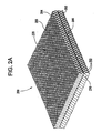
- a filter 100 includes a plurality of plates 102 defining a plurality of flow channels 104 therebetween.
- the filter 100 is rectangular in shape; however, the filter 100 can be formed in any shape or size adaptable for use within a nuclear reactor.
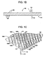
- a single plate 102 of the filter 100 is shown in Fig. 1B .
- Each plate 102 has a plurality of alternating peaks 106 and valleys 108 spaced at a predetermined spacing from one another.
- the peaks 106 and valleys 108 are configured such that when spaced side by side, on a peak to valley arrangement, the flow channel 104 is defined therebetween.
- the peaks 106 and valleys 108 may be of any design including a triangular or wave pattern and in some embodiments, plates 102 are corrugated plates. In some embodiments, the peaks 106 and valleys 108 form the channel 104 having a substantially square cross sectional area. In some embodiments, the cross sectional area is less than or equal to about 0.04 inches (1 mm), and in other embodiments the cross sectional area is greater than or equal to about 0.025 inches (0.64mm).
- the peaks 106 and valleys 108 are formed at an angle 112 from a perpendicular path 110 to a lateral surface 114 of the corrugated plate 102.
- the angle 112 may be any angle, and in one preferred embodiment, angle 112 is greater or equal to about 15 degrees. In another preferred embodiment, angle 112 is less than or equal to about 60 degrees.
- reactor coolant (not shown) flows to the lateral surface 114 of the plates 102 and generally parallel to perpendicular path 110. As the peaks 106 and valleys 108 are an angle 112 to perpendicular path 110, coolant flowing in channels 104 defined by the peaks 106 and valleys 108 is forced to change flow direction to consistent with the angle 112.
- FIG. 1C provides a close-up perspective view of filter plate 100 illustrating the plurality of corrugated plates 102 (see 102 A-D by way of example) that are arranged side by side.
- Each plate 102 is aligned with its peaks 106 to the valleys 108 of the adjacent plates 102 (for example, plate 102A and plate 102B), to form channels 104 therebetween.
- peaks 106A and 106B of plate 102A are aligned to valleys 108A and 108B, respectively, of plate 102B to form channel 104N.
- each plate 102 can be attached at some of these peaks 106 and valleys 108 at one or more connecting points 116.
- connecting point attachments can be a weld, solder, or any other suitable means for attachment including an attaching filler or adhesive added by way of spraying or dipping.
- a plurality of substantially rectangular or square flow channels 104 are formed by the peaks 106 and valleys 108 of adjacent and connected corrugated plates 102. Additionally, as each plate 102 has the peaks 106 and valleys 108 formed at an angle 112, the channels 104 are positioned at an angle 112 to the perpendicular path 110 to the lateral face 114 of the filter 100.
- the perpendicular path 110 is the general direction of coolant or fluid flow into the filter 100 at the lateral face 114. As such, any coolant entering the channels 104 at filter surface 114 will flow through the channel 104 at an angular flow of angle 112 to that of the coolant flow 110 into the filter 100.
- a multistage filter for reactor coolant includes a first filter with a plurality of adjacent plates defining a plurality of first channels therebetween. Each of said first channels are at an angle to a flow path of the coolant into the first filter.
- a second filter includes a plurality of adjacent second plates defining a plurality of second channels therebetween. Each of the second channels are at an angle to the flow of the coolant from the first filter.
- a filter 200 for a reactor coolant having a multi-stage filter arrangement with at least a first filter 202 and a second filter 204.
- the second filter 204 is positioned adjacent to the first filter 202.
- additional filters can also include in such a multi-stage filter.
- Both the first filter 202 and the second filter 204 can have a plurality of flow channels 216 and 220 defined between a plurality of plates, 203 and 205, respectively.
- the first filter 202 includes a plurality of first plates 203 defining a plurality of first channels 216.
- the second filter 204 has a plurality of second plates 205 defining a plurality of second channels 220.
- One such embodiment for each of filter 202 and 204 is described above in reference to Figs. 1A , 1B, and 1C . However, other embodiments are also within the scope of the invention.
- the second filter 204 is spaced at a distance from the first filter 202 thereby defining an intermediate zone 206 or gap therebetween.
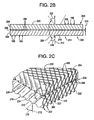
- Fig. 2B illustrates an exemplary side view of the two side by side filters.
- the first filter 202 includes a surface 211 for receiving a flow of coolant (not shown).
- the first filter 202 includes a plurality of alternating peaks 106 and valleys 108 that are formed at an angle 218 to a perpendicular path 212 to surface 211.
- the second filter 204 of the multi-stage filter 200 also includes a plurality of alternating peaks 106 and valleys 108.
- the second filter 204 is positioned adjacent to or side-by-side with the first filter 202 and can be separated by the intermediate zone 206.
- a plurality of connecting members 208 can be coupled to the first filter 202 and the second filter 204 and can fixedly couple the two filters 202 and 204 together thereby defining the intermediate zone having a gap or spacing 210.
- the peaks 106 and valleys 108 of the second filter 204 are positioned at a second angle 224 from the first angle 218.
- the second angle 224 can be, in some embodiments, less than or equal to 150 degrees.
- the peaks 106 and valleys 108 of the second filter 204 can be a third angle 222 which is also defined from the perpendicular path 212.
- the third angle 222 can be an angle that is in an opposite direction of the perpendicular path 212 than the first angle 218 of the peaks 106 and valleys 108 of the first filter.
- the third angle 222 is equal in magnitude but opposite in sign with respect to the perpendicular path 212 as the first angle 218 of the first filter 202.
- the first filter 202 and the second filter 204 are positioned side by side such that flow through the first channels 216 of the first filter 202 flow into the second channels 220 of the second filter 204.
- the second angle 224 being less than or equal to 150 degrees from the first angle 218, coolant flowing into the first filter 202 flows at the first angle 218 from the perpendicular flow 212 of coolant into the first filter 202.
- the coolant then changes directions as the coolant flows from the first flow channels 216 into the second channels 220, e.g., changes directions equal to the second angle 224.
- the first flow channels 216 of the first filter 202 can interconnect with the second flow channels 220 of the second filter 204 on a one-to-one basis.
- the peaks 106 of the first filter 202 can be aligned to the valleys 108 of the second filter 204.
- the first channels 216 provide coolant flow to a plurality of second channels 220.
- the second flow channels 220 are aligned with the first flow channels 216 such that each second channel 220 is aligned to four or more first channels 216.
- the coolant flow in the second channels 220 includes coolant received from four or more first channels 216. In some embodiments, about each 1 ⁇ 4 of each second channel 220 is aligned with a different first channel 216.
- the connecting members 208 can couple the first filter 202 and the second filter 204 together and can define the intermediate zone 206 between the two filters202 and 204.
- the intermediate zone 206 can define the spacing 210 between the two filters 202 and 204, and in some embodiments, the spacing is about 0.04 inches (1mm). In other embodiments, the spacing 210 is less than or equal to 0.05 inches (1.25mm).
- the intermediate zone 206 provides for a mixing of flow from a plurality of first channels 216 being provided to each second channel 220. This also provides the multi-stage filter 200 with improved filtering characteristics.
- Various embodiments can include one or more of a) trapping debris with the multi-stage filter 200, b) trapping debris within the intermediate zone 206, and c) providing fluid flow around any trapped debris.
- a) trapping debris with the multi-stage filter 200 b) trapping debris within the intermediate zone 206, and c) providing fluid flow around any trapped debris.
- other features or characteristics of the filter are also present although not described or particularly pointed out herein.
- a multistage filter for reactor coolant include a first filter 202 with the plurality of adjacent plates 203 defining the plurality of first channels 216 therebetween.
- the second filter 204 includes the plurality of adjacent second plates 205 defining a plurality of second channels 220 therebetween.
- Each second channel 220 of the second filter 204 is aligned to the multiple first channels 216 of the first filter 202.
- One such embodiment is shown in a close up perspective of Fig. 3 .
- a first filter 202 with first plates 203 and a second filter 204 with second plates 205 are aligned with each peak of the first plates 203.
- each peak of the first plates 203 are aligned with a valley of an adjacent plate thereby forming first channel 216 therebetween.
- a plate 203A is aligned with a plate 203B and a first channel 216A is therebetween defined.
- a plate 205A of second filter 204 defines a plurality of second channels 220 with an adjacent second plate 205B.
- second plate 205A and second plate 205B form second channels 220A and 220B
- second plate 205A and second plate 205C form another second channel 220D
- second plate 205B and second plate 205D form another second channel 220C.
- the first filter 202 made up of first plates 203 that define the first channels 216 is aligned the second filter 204 made up of second plates 205 that define the second channels 220, in this exemplary embodiment, such that multiple second channels 220 are aligned to each first channel 216.
- the first channel 216A is aligned to each of second channels 220A, 220B, 220C and 220D.
- coolant flows through each of the first channel 216 and is distributed and provided to multiple second channels 220, and in this example, to four second channels 220.
- each first channel 216 can be aligned to two or more second channels 220.
- an intermediate zone 206 may provide for additional mixing of coolant flow from first channels 216 to second channels 220.
- debris filters are adapted for filtering debris in the coolant circulating within a nuclear reactor.
- other embodiments of the invention include a lower tie plate assembly for a nuclear reactor that includes a casing having an inlet opening for conducting coolant into the lower tie plate assembly.
- a rod support member is configured for receiving a plurality of fuel rods.
- a debris filter is positioned adjacent to the rod support member.
- the debris filter can include at least a first filter and a second filter.
- the first filter can have a plurality of adjacent plates defining a plurality of first channels therebetween.
- Each of the first channels is at an angle to a flow path of the coolant into the first filter.
- the second filter can have a plurality of adjacent plates that define a plurality of second channels therebetween. Each of the second channels is at an angle to the flow of the coolant from the first filter.
- the second channels of the second filter can be offset from the first channels of the first filter such that the coolant flow in each second channel includes coolant flow from multiple first channels.
- Each of the first channels and the second channels can have a cross section less than or equal to about 0.04 square inches (25.8mm 2 ) in some preferred embodiments.
- Such flow channels cross sections can be of any shape and in one embodiment is substantially square in shape.
- a plurality of connecting members coupling the second filter to the first filter to create a substantially unobstructed intermediate zone between the first filter and the second filter.
- an angle of the first channels is greater than or equal to about 15 degrees from a coolant flow entering the first filter. Additionally, the angle of the second channels is less than or equal to about 150 degrees from the coolant flow from the first filter.
- the casing can be dimensioned to provide a higher flow rate in a center portion of the filter than a flow rate along a perimeter portion of the filter. In such cases, the flow rate arrangement provides for washing filtered debris from the center of the multi-stage filter into the corners of the casing between the casing and the multi-stage filter.
- the casing can also be configured to include a filter placement opening that is adapted for insertion of the multi-stage filter into the casing adjacent to the rod support member and a closure plate.
- the multi-stage filter can generally be dimensioned to substantially fill the casing such that substantially all of the coolant flows through both the first filter and the second filter.
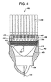
- a lower tie plate assembly 400 for a nuclear reactor is illustrated with a plurality of fuel rods 408 coupled thereto.
- the lower tie plate assembly 400 includes a lower tie plate casing 402 defining an inlet opening 404 and a flow chamber 420. Coolant flows as shown as 414 into the reactor core through this inlet 404 and chamber 420.
- a rod support member 406 includes rod holes 412 for receiving and supporting the plurality of fuel rods 408, which may include non-fuel rods such as water rods.
- Some of the fuel rods 408 can have end caps 410 for attaching the fuel rods to the rod support member 406.
- the rod support member 406 can also include a plurality of openings 407 to allow for the passage of coolant from below the rod support member 406 up to and around the fuel rods 408.
- a filter cover plate 418 can provide access to the filter 200 and can be adjacent to rod support member 406.
- the filter cover plate 418 and/or lower end plate casing 402 can be adapted to support or fixedly couple the filter 200 into a position adjacent the rod support member 406.
- the filter 200 receives coolant flow 414 from inlet 404 through chamber 420.
- the coolant entering the filter 200 can be substantially parallel to perpendicular path 212.
- the coolant flow through the filter 200 and directly into the lower portion of the rod support member 406 and up and through the rod support member 406 to the fuel rods 408.
- the lower tie plate casing 402 can be configured to provide a higher flow rate of coolant near the center portion of the filter 200 and a lower flow rate at or near the perimeter of the filter 200. As such, at least a portion of the debris in the coolant filtered by the filter 200 can be forced by the difference in flow rates and associated pressures to one or more of the corners 416 of the chamber 420.
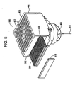
- a lower tie plate assembly 500 is exploded to illustrate the separate parts according to one embodiment of the invention.
- the casing 402 defines a filter access opening 502 for receiving the filter 200 into the casing 402.
- the filter cover plate 418 closes the opening 502.
- the filter cover plate 418 is welded or otherwise fixedly attached to seal the lower tie plate casing 402.
- a fuel assembly for a boiling coolant reactor in another embodiment, includes a lower tie plate with a rod support member and an upper tie plate. A plurality of fuel rods extend between the upper tie plate and the lower tie plate. A casing surrounds the lower tie plate, the upper tie plate, and the fuel rods and defines an inlet opening through the lower tie plate assembly for conducting coolant into a reactor core. A debris filter is position positioned adjacent to the rod support member.
- the debris filter is one of the debris filters described above, by way of example.
- the filter includes a first filter, a second filter, and a plurality of connecting members.
- the first filter has a plurality of first plates defining a plurality of first flow channels. Each of the first flow channels are at a first angle to a flow path of the coolant into the first filter.
- the second filter has a plurality of second plates defining a plurality of second flow channels. Each of the second flow channels is at a second angle to the flow of the coolant into the first filter. The second angle is in an opposite direction to the first angle.
- Each of the second flow channels can be offset from each of the first flow channels.
- the connecting members can fixedly connect the second filter to the first filter and can create an intermediate zone therebetween. In one embodiment, the intermediate zone is substantially unobstructed.
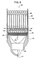
- a partial fuel assembly 600 includes a lower tie casing 402 that includes a coolant inlet 404 and a rod support member 406.
- the rod support member 406 includes rod holes 412 for receiving a plurality of fuel rods 408.
- a filter 200 is positioned adjacent to the rod support member 406 and a filter cover plate 418.
- the filter 200 can be any embodiment of the filter described above and herein.
- One or more spacers 604 supports and spaces the upper portions of the fuel rods 408.
- a fuel assembly casing 602 can surround the fuel rods 408, the spacers 604, the rod support member 406, the lower tie plate casing 402, and an upper tie plate (not shown).
Landscapes
- Physics & Mathematics (AREA)
- Engineering & Computer Science (AREA)
- Plasma & Fusion (AREA)
- General Engineering & Computer Science (AREA)
- High Energy & Nuclear Physics (AREA)
- Structure Of Emergency Protection For Nuclear Reactors (AREA)
- Filtration Of Liquid (AREA)
- Monitoring And Testing Of Nuclear Reactors (AREA)
Applications Claiming Priority (1)
| Application Number | Priority Date | Filing Date | Title |
|---|---|---|---|
| US11/024,953 US8317035B2 (en) | 2004-12-30 | 2004-12-30 | Debris filter |
Publications (2)
| Publication Number | Publication Date |
|---|---|
| EP1677313A1 EP1677313A1 (en) | 2006-07-05 |
| EP1677313B1 true EP1677313B1 (en) | 2008-07-02 |
Family
ID=36096286
Family Applications (1)
| Application Number | Title | Priority Date | Filing Date |
|---|---|---|---|
| EP05257988A Expired - Lifetime EP1677313B1 (en) | 2004-12-30 | 2005-12-22 | Debris filter |
Country Status (6)
| Country | Link |
|---|---|
| US (2) | US8317035B2 (enExample) |
| EP (1) | EP1677313B1 (enExample) |
| JP (1) | JP5603529B2 (enExample) |
| DE (1) | DE602005007848D1 (enExample) |
| ES (1) | ES2308406T3 (enExample) |
| TW (1) | TWI366198B (enExample) |
Families Citing this family (31)
| Publication number | Priority date | Publication date | Assignee | Title |
|---|---|---|---|---|
| JP5040493B2 (ja) | 2006-12-04 | 2012-10-03 | ソニー株式会社 | 撮像装置及び撮像方法 |
| US9620249B2 (en) * | 2007-08-31 | 2017-04-11 | Global Nuclear Fuel—Americas, LLC | Debris shield upper tie plate for nuclear fuel assembly and method to shield assembly from debris |
| US20090060114A1 (en) * | 2007-08-31 | 2009-03-05 | Global Nuclear Fuel - Americas, Llc | Debris shield for upper tie plate in a nuclear fuel bundle and method for filtering debris |
| US8396182B2 (en) * | 2007-08-31 | 2013-03-12 | Global Nuclear Fuel—Americas, LLC | Method and apparatus to shield a nuclear fuel assembly with removable debris shield in upper tie |
| KR101515116B1 (ko) | 2007-12-26 | 2015-04-24 | 토륨 파워 인코포레이티드 | 원자로(대용물), 원자로(대용물)를 위한 드라이버-브리딩 모듈들로 구성된 연료 집합체 및 연료 집합체용 연료 요소 |
| US8116423B2 (en) | 2007-12-26 | 2012-02-14 | Thorium Power, Inc. | Nuclear reactor (alternatives), fuel assembly of seed-blanket subassemblies for nuclear reactor (alternatives), and fuel element for fuel assembly |
| ATE515776T1 (de) * | 2008-09-16 | 2011-07-15 | Areva Np | Trümmerfilter zur rückhaltung von feststoffpartikeln in der kühlmittelflüssigkeit eines kernreaktors |
| ES2715529T3 (es) | 2008-12-25 | 2019-06-04 | Thorium Power Inc | Un elemento combustible y un método para fabricar un elemento combustible para un conjunto combustible de un reactor nuclear |
| EP2204819B1 (en) * | 2008-12-31 | 2014-06-04 | Areva Np | Debris filter for use in a nuclear fuel assembly |
| US8548113B2 (en) * | 2009-08-28 | 2013-10-01 | Global Nuclear Fuel - Americas, Llc | Debris mitigation upper tie plates and fuel bundles using the same |
| US10192644B2 (en) | 2010-05-11 | 2019-01-29 | Lightbridge Corporation | Fuel assembly |
| WO2011143172A1 (en) | 2010-05-11 | 2011-11-17 | Thorium Power, Inc. | Fuel assembly with metal fuel alloy kernel and method of manufacturing thereof |
| US10170207B2 (en) | 2013-05-10 | 2019-01-01 | Thorium Power, Inc. | Fuel assembly |
| US8611488B2 (en) * | 2011-02-14 | 2013-12-17 | Global Nuclear Fuel—Americas, LLC | Debris exclusion and retention device for a fuel assembly |
| EP2525361A1 (en) * | 2011-05-20 | 2012-11-21 | Areva NP | Lower nozzle for use in nuclear fuel assembly |
| US8877054B2 (en) * | 2011-06-01 | 2014-11-04 | Transco Products Inc. | High capacity suction strainer for an emergency core cooling system in a nuclear power plant |
| CN103403811B (zh) * | 2011-10-14 | 2016-01-06 | 中科华核电技术研究院有限公司 | 一种下管座过滤装置及使用该装置的防异物下管座 |
| US10395784B2 (en) | 2012-09-11 | 2019-08-27 | Ge-Hitachi Nuclear Energy Americas Llc | Method and system for external alternate suppression pool cooling for a BWR |
| CN103337262B (zh) * | 2013-06-18 | 2016-06-22 | 中国核动力研究设计院 | 一种具有过滤异物功能的下管座 |
| JP6239887B2 (ja) * | 2013-07-25 | 2017-11-29 | 株式会社グローバル・ニュークリア・フュエル・ジャパン | 燃料集合体 |
| US9715947B2 (en) * | 2013-08-09 | 2017-07-25 | Ge-Hitachi Nuclear Energy Americas Llc | Systems for debris mitigation in nuclear reactor safety systems |
| USD788316S1 (en) * | 2016-05-13 | 2017-05-30 | Elliot Kremerman | Laboratory filter |
| EP3255421B1 (en) * | 2016-06-10 | 2020-01-01 | coatmaster AG | Device for the contactless and non-destructive testing of a surface by measuring its infrared radiation |
| KR102656310B1 (ko) * | 2016-09-06 | 2024-04-09 | 웨스팅하우스 일렉트릭 스웨덴 아베 | 연료 집합체 |
| JP6925172B2 (ja) * | 2017-05-31 | 2021-08-25 | 三菱重工業株式会社 | 原子炉格納構造 |
| US10923237B2 (en) * | 2017-08-28 | 2021-02-16 | Global Nuclear Fuel—Americas, LLC | Debris filters for nuclear fuel assembly and method of using the same |
| CN111095431B (zh) * | 2017-12-28 | 2023-09-19 | Tvel股份公司 | 核反应堆燃料组件 |
| SI3709310T1 (sl) * | 2019-03-12 | 2022-01-31 | Westinghouse Electric Sweden Ab | Filter in gorivni sestav za jedrsko elektrarno |
| WO2020236702A2 (en) * | 2019-05-21 | 2020-11-26 | Westinghouse Electric Company Llc | Bottom nozzle with internal debris filter |
| US20200373025A1 (en) * | 2019-05-22 | 2020-11-26 | Westinghouse Electric Company Llc | Debris filtering arrangement for nuclear fuel assembly bottom nozzle and bottom nozzle including same |
| CN113362976A (zh) * | 2021-06-04 | 2021-09-07 | 中国核动力研究设计院 | 一种高效过滤的下管座、燃料组件和核反应堆 |
Family Cites Families (36)
| Publication number | Priority date | Publication date | Assignee | Title |
|---|---|---|---|---|
| US3113102A (en) * | 1960-07-15 | 1963-12-03 | Schulze Karl Ludwig | Trickling filter |
| US5112570A (en) | 1988-04-04 | 1992-05-12 | Hewlett-Packard Company | Two-phase pressure drop reduction bwr assembly design |
| US5219517A (en) | 1989-12-14 | 1993-06-15 | Abb Atom Ab | Fuel assembly for a boiling water nuclear reactor |
| SE465191B (sv) | 1989-12-14 | 1991-08-05 | Asea Atom Ab | Braenslepatron foer en kaernreaktor av kokarvattentyp |
| US5030412A (en) | 1990-05-04 | 1991-07-09 | Advanced Nuclear Fuels Corporation | Fuel assembly debris screen |
| US5384814A (en) | 1993-04-12 | 1995-01-24 | General Electric Company | Lower tie plate strainers for boiling water reactors |
| US5483564A (en) | 1993-04-12 | 1996-01-09 | General Electric Company | Lower tie plate strainers including double corrugated strainers for boiling water reactors |
| US5490185A (en) | 1993-07-23 | 1996-02-06 | Westinghouse Electric Corporation | System for automatic refueling of a nuclear reactor |
| DE4344082C1 (de) * | 1993-12-23 | 1994-12-22 | Goldschmidt Ag Th | Verfahren zur Herstellung von Organopolysiloxanen mit über Kohlenstoff an Silicium gebundenen sekundären Aminoalkylgruppen |
| US5488634A (en) | 1994-02-10 | 1996-01-30 | General Electric Company | Lower tie plate debris catcher for a nuclear reactor |
| JPH08105988A (ja) | 1994-10-04 | 1996-04-23 | Nuclear Fuel Ind Ltd | 原子燃料集合体 |
| US5528640A (en) | 1994-11-07 | 1996-06-18 | General Electric Company | Low pressure double offset plate catcher for a nuclear reactor |
| US5793636A (en) | 1995-04-28 | 1998-08-11 | Westinghouse Electric Corporation | Integrated fuel management system |
| US5610961A (en) | 1995-10-12 | 1997-03-11 | General Electric Company | Fuel assembly structure using channel for load support |
| US5627866A (en) | 1995-10-12 | 1997-05-06 | General Electric Company | Fuel assembly structure using channel for load support |
| US5748695A (en) | 1995-11-07 | 1998-05-05 | General Electric Company | Fuel assembly structure selectively using channel and coolant rod for load support and method |
| US5923717A (en) | 1996-01-29 | 1999-07-13 | General Electric Company | Method and system for determining nuclear core loading arrangements |
| SE508059C2 (sv) * | 1996-06-20 | 1998-08-17 | Asea Atom Ab | Kärnbränslepatron uppbyggd av ett flertal på varandra staplade bränsleenheter |
| DE29615575U1 (de) * | 1996-09-06 | 1997-01-16 | Siemens AG, 80333 München | Brennelement mit Trümmerfilter |
| US5960051A (en) | 1997-03-03 | 1999-09-28 | General Electric Company | Methods and apparatus for moving fuel bundles in a nuclear reactor |
| WO1998041991A1 (en) | 1997-03-17 | 1998-09-24 | Hitachi, Ltd. | Method of operating reactor |
| FR2771025B1 (fr) * | 1997-11-17 | 2000-01-28 | Air Liquide | Bande ondulee pour garnissage ondule-croise et son application a des colonnes de distillation embarquees |
| US6338149B1 (en) | 1998-07-31 | 2002-01-08 | Westinghouse Electric Company Llc | Change monitoring system for a computer system |
| JP3977969B2 (ja) * | 1999-11-17 | 2007-09-19 | 株式会社日立製作所 | 燃料集合体 |
| US6697447B1 (en) | 1999-12-30 | 2004-02-24 | General Electric Company | Maximum extended load line limit analysis for a boiling water nuclear reactor |
| DE60124464T2 (de) | 2000-08-01 | 2007-09-27 | General Electric Co. | Kernbrennstabbündel mit Trümmerfänger |
| JP3778787B2 (ja) * | 2000-08-21 | 2006-05-24 | 原子燃料工業株式会社 | 沸騰水型原子炉用燃料集合体の下部タイプレート |
| US6611572B2 (en) | 2000-12-29 | 2003-08-26 | Global Nuclear Fuel - Americas, L.L.C. | Determination of operating limit minimum critical power ratio |
| JP2002214377A (ja) * | 2001-01-19 | 2002-07-31 | Nuclear Fuel Ind Ltd | 沸騰水型核燃料集合体の異物捕捉装置 |
| SE521610C2 (sv) * | 2001-01-22 | 2003-11-18 | Westinghouse Atom Ab | Filter och bränslepatron för en nukleär anläggning av lättvattentyp |
| TW557450B (en) * | 2001-07-16 | 2003-10-11 | Toshiba Corp | Fuel supporting attachment, fuel inlet mechanism, and fuel assembly |
| US20030116871A1 (en) * | 2001-12-21 | 2003-06-26 | Steven Ringo | Structured packing |
| DE10230325A1 (de) * | 2002-07-05 | 2004-01-15 | Julius Montz Gmbh | Bodenkolonne |
| US6674826B1 (en) | 2002-09-23 | 2004-01-06 | Westinghouse Electric Company Llc | Method of operating a nuclear power plant at multiple power levels |
| WO2004030809A1 (en) * | 2002-10-03 | 2004-04-15 | Koch-Glitsch, Lp | Structured packing plate and element and method of fabricating same |
| US7280946B2 (en) | 2003-04-30 | 2007-10-09 | Global Nuclear Fuel-Americas, Llc | Method and arrangement for determining pin enrichments in fuel bundle of nuclear reactor |
-
2004
- 2004-12-30 US US11/024,953 patent/US8317035B2/en active Active - Reinstated
-
2005
- 2005-12-20 TW TW094145337A patent/TWI366198B/zh not_active IP Right Cessation
- 2005-12-21 JP JP2005367367A patent/JP5603529B2/ja not_active Expired - Lifetime
- 2005-12-22 DE DE602005007848T patent/DE602005007848D1/de not_active Expired - Lifetime
- 2005-12-22 ES ES05257988T patent/ES2308406T3/es not_active Expired - Lifetime
- 2005-12-22 EP EP05257988A patent/EP1677313B1/en not_active Expired - Lifetime
-
2012
- 2012-06-29 US US13/538,067 patent/US20120273408A1/en not_active Abandoned
Also Published As
| Publication number | Publication date |
|---|---|
| JP2006189434A (ja) | 2006-07-20 |
| TWI366198B (en) | 2012-06-11 |
| US8317035B2 (en) | 2012-11-27 |
| TW200636758A (en) | 2006-10-16 |
| ES2308406T3 (es) | 2008-12-01 |
| EP1677313A1 (en) | 2006-07-05 |
| US20120273408A1 (en) | 2012-11-01 |
| US20060283790A1 (en) | 2006-12-21 |
| JP5603529B2 (ja) | 2014-10-08 |
| DE602005007848D1 (de) | 2008-08-14 |
Similar Documents
| Publication | Publication Date | Title |
|---|---|---|
| EP1677313B1 (en) | Debris filter | |
| EP1179823B1 (en) | Nuclear fuel assembly comprising a debris catcher | |
| US8475659B2 (en) | Strainers for emergency core cooling systems—ECCS | |
| EP0347961B1 (en) | Plate type heat exchanger | |
| JP4970277B2 (ja) | フィン付きストレーナ | |
| EP1356474B1 (en) | Filter for cooling water in a light water cooled nuclear reactor | |
| JPH04230892A (ja) | 燃料集合体の破片フィルタ | |
| DE4407080A1 (de) | Wärmetauscher | |
| JPH08240680A (ja) | 原子炉用の下部タイプレート・アセンブリ、並びに原子炉用の燃料バンドル及び下部タイプレート・アセンブリ | |
| US20120037572A1 (en) | Strainer wall structure including curved sections, method of manufacturing the same, and filtering method using the same | |
| JP2014519032A (ja) | 原子炉設備のためのデブリフィルタおよびそのようなデブリフィルタを含む核燃料アセンブリ | |
| EP0655746A1 (en) | Strainers for boiling water reactors | |
| US4854382A (en) | Plate heat exchanger | |
| JP2023027320A (ja) | 原子燃料集合体用のデブリフィルタの形成方法 | |
| KR102656310B1 (ko) | 연료 집합체 | |
| EP0946946B1 (en) | A filter for a nuclear fuel assembly | |
| JPH11109074A (ja) | 原子炉燃料集合体及びその下部ノズル | |
| CN211782979U (zh) | 翅片及热交换器 | |
| JP2010190515A (ja) | ヒートシンク | |
| JP2001116872A (ja) | 燃料集合体のデブリフィルタ | |
| JP2004523762A (ja) | 軽水炉のためのフィルタおよび燃料アセンブリ | |
| CN217383904U (zh) | 一种板式换热器 | |
| CN218155675U (zh) | 一种板式热交换器 | |
| JP4366242B2 (ja) | 燃料集合体 | |
| JP5241809B2 (ja) | デブリフィルタ |
Legal Events
| Date | Code | Title | Description |
|---|---|---|---|
| PUAI | Public reference made under article 153(3) epc to a published international application that has entered the european phase |
Free format text: ORIGINAL CODE: 0009012 |
|
| AK | Designated contracting states |
Kind code of ref document: A1 Designated state(s): AT BE BG CH CY CZ DE DK EE ES FI FR GB GR HU IE IS IT LI LT LU LV MC NL PL PT RO SE SI SK TR |
|
| AX | Request for extension of the european patent |
Extension state: AL BA HR MK YU |
|
| 17P | Request for examination filed |
Effective date: 20070105 |
|
| 17Q | First examination report despatched |
Effective date: 20070212 |
|
| AKX | Designation fees paid |
Designated state(s): CH DE ES FI LI SE |
|
| GRAP | Despatch of communication of intention to grant a patent |
Free format text: ORIGINAL CODE: EPIDOSNIGR1 |
|
| GRAS | Grant fee paid |
Free format text: ORIGINAL CODE: EPIDOSNIGR3 |
|
| GRAA | (expected) grant |
Free format text: ORIGINAL CODE: 0009210 |
|
| AK | Designated contracting states |
Kind code of ref document: B1 Designated state(s): CH DE ES FI LI SE |
|
| REG | Reference to a national code |
Ref country code: CH Ref legal event code: EP |
|
| REF | Corresponds to: |
Ref document number: 602005007848 Country of ref document: DE Date of ref document: 20080814 Kind code of ref document: P |
|
| REG | Reference to a national code |
Ref country code: CH Ref legal event code: NV Representative=s name: SERVOPATENT GMBH |
|
| REG | Reference to a national code |
Ref country code: SE Ref legal event code: TRGR |
|
| REG | Reference to a national code |
Ref country code: ES Ref legal event code: FG2A Ref document number: 2308406 Country of ref document: ES Kind code of ref document: T3 |
|
| PLBE | No opposition filed within time limit |
Free format text: ORIGINAL CODE: 0009261 |
|
| STAA | Information on the status of an ep patent application or granted ep patent |
Free format text: STATUS: NO OPPOSITION FILED WITHIN TIME LIMIT |
|
| 26N | No opposition filed |
Effective date: 20090403 |
|
| PGFP | Annual fee paid to national office [announced via postgrant information from national office to epo] |
Ref country code: DE Payment date: 20191119 Year of fee payment: 15 |
|
| REG | Reference to a national code |
Ref country code: CH Ref legal event code: PCAR Free format text: NEW ADDRESS: WANNERSTRASSE 9/1, 8045 ZUERICH (CH) |
|
| REG | Reference to a national code |
Ref country code: DE Ref legal event code: R119 Ref document number: 602005007848 Country of ref document: DE |
|
| PG25 | Lapsed in a contracting state [announced via postgrant information from national office to epo] |
Ref country code: DE Free format text: LAPSE BECAUSE OF NON-PAYMENT OF DUE FEES Effective date: 20210701 |
|
| PGFP | Annual fee paid to national office [announced via postgrant information from national office to epo] |
Ref country code: FI Payment date: 20241121 Year of fee payment: 20 |
|
| PGFP | Annual fee paid to national office [announced via postgrant information from national office to epo] |
Ref country code: SE Payment date: 20241121 Year of fee payment: 20 |
|
| PGFP | Annual fee paid to national office [announced via postgrant information from national office to epo] |
Ref country code: ES Payment date: 20250102 Year of fee payment: 20 |
|
| PGFP | Annual fee paid to national office [announced via postgrant information from national office to epo] |
Ref country code: CH Payment date: 20250101 Year of fee payment: 20 |