EP1677040B1 - Schlauchkupplung - Google Patents
Schlauchkupplung Download PDFInfo
- Publication number
- EP1677040B1 EP1677040B1 EP06075084A EP06075084A EP1677040B1 EP 1677040 B1 EP1677040 B1 EP 1677040B1 EP 06075084 A EP06075084 A EP 06075084A EP 06075084 A EP06075084 A EP 06075084A EP 1677040 B1 EP1677040 B1 EP 1677040B1
- Authority
- EP
- European Patent Office
- Prior art keywords
- hose
- tubular body
- sealing
- axial
- layer
- Prior art date
- Legal status (The legal status is an assumption and is not a legal conclusion. Google has not performed a legal analysis and makes no representation as to the accuracy of the status listed.)
- Expired - Lifetime
Links
Images


Classifications
-
- F—MECHANICAL ENGINEERING; LIGHTING; HEATING; WEAPONS; BLASTING
- F16—ENGINEERING ELEMENTS AND UNITS; GENERAL MEASURES FOR PRODUCING AND MAINTAINING EFFECTIVE FUNCTIONING OF MACHINES OR INSTALLATIONS; THERMAL INSULATION IN GENERAL
- F16L—PIPES; JOINTS OR FITTINGS FOR PIPES; SUPPORTS FOR PIPES, CABLES OR PROTECTIVE TUBING; MEANS FOR THERMAL INSULATION IN GENERAL
- F16L11/00—Hoses, i.e. flexible pipes
- F16L11/04—Hoses, i.e. flexible pipes made of rubber or flexible plastics
- F16L11/08—Hoses, i.e. flexible pipes made of rubber or flexible plastics with reinforcements embedded in the wall
- F16L11/081—Hoses, i.e. flexible pipes made of rubber or flexible plastics with reinforcements embedded in the wall comprising one or more layers of a helically wound cord or wire
- F16L11/082—Hoses, i.e. flexible pipes made of rubber or flexible plastics with reinforcements embedded in the wall comprising one or more layers of a helically wound cord or wire two layers
-
- F—MECHANICAL ENGINEERING; LIGHTING; HEATING; WEAPONS; BLASTING
- F16—ENGINEERING ELEMENTS AND UNITS; GENERAL MEASURES FOR PRODUCING AND MAINTAINING EFFECTIVE FUNCTIONING OF MACHINES OR INSTALLATIONS; THERMAL INSULATION IN GENERAL
- F16L—PIPES; JOINTS OR FITTINGS FOR PIPES; SUPPORTS FOR PIPES, CABLES OR PROTECTIVE TUBING; MEANS FOR THERMAL INSULATION IN GENERAL
- F16L11/00—Hoses, i.e. flexible pipes
- F16L11/04—Hoses, i.e. flexible pipes made of rubber or flexible plastics
- F16L11/12—Hoses, i.e. flexible pipes made of rubber or flexible plastics with arrangements for particular purposes, e.g. specially profiled, with protecting layer, heated, electrically conducting
-
- F—MECHANICAL ENGINEERING; LIGHTING; HEATING; WEAPONS; BLASTING
- F16—ENGINEERING ELEMENTS AND UNITS; GENERAL MEASURES FOR PRODUCING AND MAINTAINING EFFECTIVE FUNCTIONING OF MACHINES OR INSTALLATIONS; THERMAL INSULATION IN GENERAL
- F16L—PIPES; JOINTS OR FITTINGS FOR PIPES; SUPPORTS FOR PIPES, CABLES OR PROTECTIVE TUBING; MEANS FOR THERMAL INSULATION IN GENERAL
- F16L33/00—Arrangements for connecting hoses to rigid members; Rigid hose connectors, i.e. single members engaging both hoses
- F16L33/01—Arrangements for connecting hoses to rigid members; Rigid hose connectors, i.e. single members engaging both hoses adapted for hoses having a multi-layer wall
-
- F—MECHANICAL ENGINEERING; LIGHTING; HEATING; WEAPONS; BLASTING
- F16—ENGINEERING ELEMENTS AND UNITS; GENERAL MEASURES FOR PRODUCING AND MAINTAINING EFFECTIVE FUNCTIONING OF MACHINES OR INSTALLATIONS; THERMAL INSULATION IN GENERAL
- F16L—PIPES; JOINTS OR FITTINGS FOR PIPES; SUPPORTS FOR PIPES, CABLES OR PROTECTIVE TUBING; MEANS FOR THERMAL INSULATION IN GENERAL
- F16L33/00—Arrangements for connecting hoses to rigid members; Rigid hose connectors, i.e. single members engaging both hoses
- F16L33/22—Arrangements for connecting hoses to rigid members; Rigid hose connectors, i.e. single members engaging both hoses with means not mentioned in the preceding groups for gripping the hose between inner and outer parts
- F16L33/23—Arrangements for connecting hoses to rigid members; Rigid hose connectors, i.e. single members engaging both hoses with means not mentioned in the preceding groups for gripping the hose between inner and outer parts the outer parts being segmented, the segments being pressed against the hose by tangentially arranged members
-
- F—MECHANICAL ENGINEERING; LIGHTING; HEATING; WEAPONS; BLASTING
- F16—ENGINEERING ELEMENTS AND UNITS; GENERAL MEASURES FOR PRODUCING AND MAINTAINING EFFECTIVE FUNCTIONING OF MACHINES OR INSTALLATIONS; THERMAL INSULATION IN GENERAL
- F16L—PIPES; JOINTS OR FITTINGS FOR PIPES; SUPPORTS FOR PIPES, CABLES OR PROTECTIVE TUBING; MEANS FOR THERMAL INSULATION IN GENERAL
- F16L59/00—Thermal insulation in general
- F16L59/14—Arrangements for the insulation of pipes or pipe systems
- F16L59/141—Arrangements for the insulation of pipes or pipe systems in which the temperature of the medium is below that of the ambient temperature
-
- B—PERFORMING OPERATIONS; TRANSPORTING
- B63—SHIPS OR OTHER WATERBORNE VESSELS; RELATED EQUIPMENT
- B63B—SHIPS OR OTHER WATERBORNE VESSELS; EQUIPMENT FOR SHIPPING
- B63B27/00—Arrangement of ship-based loading or unloading equipment for cargo or passengers
- B63B27/30—Arrangement of ship-based loading or unloading equipment for transfer at sea between ships or between ships and off-shore structures
- B63B27/34—Arrangement of ship-based loading or unloading equipment for transfer at sea between ships or between ships and off-shore structures using pipe-lines
Definitions
- This invention relates to hose, and more particularly relates to hose having improved axial strength.
- the invention is especially concerned with hose which can be used in cryogenic conditions.
- the invention also relates to an end fitting for a hose, and to a method of making a hose.
- Typical applications for hose involve the pumping of fluids from a fluid reservoir under pressure. Examples include supplying of domestic heating oil or LPG to a boiler; transporting produced oilfield liquids and/or gases from a fixed or floating production platform to the cargo hold of a ship, or from a ship cargo hold to a land-based storage unit; delivering of fuel to racing cars, especially during refuelling in formula 1; and conveying corrosive fluids, such as sulphuric acid.
- hose for the transport of fluids, such as liquefied gases, at low temperature.
- fluids such as liquefied gases
- hose is commonly used to transport liquefied gases such as liquefied natural gas (LNG) and liquefied propane gas (LPG).
- LNG liquefied natural gas
- LPG liquefied propane gas
- any given length must be at least partially constructed of flexible materials, i.e., non-rigid materials.
- the structure of such hose generally comprises a tubular body of flexible material arranged between an inner and outer helically wound retaining wires. It is conventional for the two wires to be wound at the same pitch, but to have the windings displaced by half a pitch width from one another.
- the tubular body typically comprises inner and outer layers with an intermediate sealing layer.
- the inner and outer layers provide the structure with the strength to carry the fluid therein.
- the inner and outer layers of the tubular body comprise fabric layers formed of a polyester such as polyethylene terephthalate.
- the intermediate sealing layer provides a seal to prevent the fluid from penetrating the hose, and is typically a polymeric film.
- the retaining wires are typically applied under tension around the inside and outside surfaces of the tubular body.
- the retaining wires act primarily to preserve the geometry of the tubular body.
- the outer wire may act to restrain excessive hoop deformation of the hose under high pressure.
- the inner and outer wires may also act to resist crushing of the hose.
- a hose of this general type is described in European patent publication no. 0076540A1 .
- the hose described in this specification includes an intermediate layer of biaxially oriented polypropylene, which is said to improve the ability of the hose to resist the fatigue caused by repeated flexing.
- hose is described in GB-2223817A .
- the hose described in this publication is a composite hose comprising an inner helical metallic core, a plurality of layers of plastics material fibres and films wound on the core, at least one layer of glass cloth and at least one layer of aluminium foil disposed adjacent one another and wound onto the plastics material, and an outer helical metallic former.
- This hose is said to be suitable for transporting flammable fuels and oils.
- hose described in GB-1034956A is an electrical hose or conduit, i.e., it is intended for carrying electrical wires rather than for the transport of fluids.
- the hose described in GB-1034956A comprises:
- the braided metal sheath is made to follow the convolutions of the inner wire by temporarily winding a further wire around the sheath during manufacture of the hose.
- GB323352 discloses a pipe coupling for use with flexible externally armoured hose.
- hose Many applications of hose require the hose to be supported along its length. This especially applies to the transport of the produced liquids and/or gases mentioned above. Without additional support, conventional hose is often incapable of supporting its own weight, or the weight of the fluid contained therein.
- the present invention also relates to an improvement in the termination of the ends of the hose.
- an end fitting for a hose as defined in claim 1.
- the hose preferably comprises a tubular body of flexible material arranged between inner and outer gripping members, wherein the hose further comprises an axial strengthening means adapted to reduce deformation of the tubular body when the tubular body is subjected to axial tension, and the axial strengthening means is further adapted to exert a radially inward force on at least part of the tubular body when axial strengthening means is subjected to axial tensioning.
- the failure strain of the tubular body and the axial strengthening means are within the range of 1 to 10%. More preferably the failure strain is in excess of 5% at ambient and cryogenic temperatures.
- the axial strengthening means improves the ability of the hose to cope with axial stresses, and at the same time can contribute to the structural integrity of the hose during axial tensioning by pressing against at least part of the tubular body.
- the materials of the tubular body and the axial strengthening means are advantageously compatible so that they each perform in a similar manner when in operation, so that no single component is subjected to excessive stresses and strains. This means that the materials of the tubular body and the axial strengthening means respond to strain in:a similar manner.
- a bend strain (for a cylindrical component) of at least 3% is generally needed for the type of hose applications primarily envisaged by the present invention.
- the axial strengthening means is made of a non-metallic material, especially a plastics material - suitable materials are discussed in detail below. This is because metallic materials are unlikely to have the desired strain characteristics.
- tubular body and the axial strengthening means comprise the same material, most preferably ultra high molecular weight polyethylene (UHMWPE), as described in further detail below.
- UHMWPE ultra high molecular weight polyethylene
- the tubular body preferably comprises at least one reinforcing layer and at least one sealing layer. More preferably, there are at least two reinforcing layers with the sealing layer sandwiched therebetween.
- a further reinforcing layer is provided between the outer gripping member and the axial strengthening means.
- the ultimate strength of the reinforcing layer(s) is preferably between 100 and 700 kN for an 8" (200 mm) diameter hose. It is preferable that the bend strain at failure of the reinforcing layer(s) is in the range 2% to 15%. Desirably, further reinforcing layer(s) are the same material as the axial strengthening means, most preferably UHMWPE.
- the axial strengthening means comprises a generally tubular sheath formed of a sheet of material provided in a tubular shape, such that the sheath can maintain the integrity of its tubular shape when subjected to axial tension.
- the hose may be provided with two or more tubular sheaths in order to further improve the performance of the hose under axial tension.
- the axial strengthening means is provided in the form of a generally tubular braid.
- braid refers to a material which is formed of two or more fibres or yarns which have been intertwined to form an elongated structure. It is a feature of braid that it can elongate when subjected to an axial tension. It is a further feature of braid that, when provided in a tubular form, its diameter will reduce when the braid is subjected to axial tension.
- the braid will exert a radially inward force on at least part of the tubular body when subjected to axial tension.
- the entire tubular sheath is provided in the form of the braid. However, it is possible for only one or more parts of the length of the tubular sheath to be provided in the form of the braid.
- the braid extends all the way around the circumference of the tubular sheath. However, it is possible for only part of the circumference of the tubular sheath to be provided in the form of the braid.
- the braid may be provided in a biaxial form (i.e. in which the braid is formed of only two intertwining fibres or yarns) or in a triaxial form (i.e. in which there are also longitudinally extending fibres or yarns, for increased axial strength).
- the axial strengthening means in the form of a braid, it may be provided in other forms which meet the functional requirements specified above.
- the axial strengthening means may be provided as a suitable arrangement of cords or ropes helically wrapped around the tubular body.
- the materials of construction of the hose should be selected to enable the hose to perform in the environment for which it is intended.
- the hose to be able to transport pressurised fluids therethrough without leakage of the fluid through the walls of the hose.
- the hose to withstand repeated flexing, and to withstand the axial stresses caused by the combination of the hose and fluid weight.
- the materials should be capable of operating at extremely cold temperatures without any significant reduction in performance.
- the main purpose of the or each reinforcing layer is to withstand the hoop stresses which the hose is subjected to during transport of fluids therethrough.
- any reinforcing layer which has the required degree of flexibility, and which can withstand the necessary stresses, will be adequate.
- the or each reinforcing layer must be able to withstand cryogenic temperatures.
- the or each reinforcing layer is formed of a sheet of material which has been wound into a tubular form by winding the sheet material in a helical manner. This means that the or each reinforcing layer does not have much resistance to axial tension, as the application of an axial force will tend to pull the windings apart.
- the or each reinforcing layer may comprise a single continuous layer of the sheet material, or may comprise two or more single continuous layers of the sheet material. However, more usually (and depending on the length of the hose) the or each layer of the sheet material would be formed of a plurality of separate lengths of sheet material arranged along the length of the hose.
- each reinforcing layer comprises a fabric, most preferably a woven fabric.
- the or each reinforcing layer may be a natural or synthetic material.
- the or each reinforcing layer is conveniently formed of a synthetic polymer, such as a polyester, a polyamide or a polyolefin.
- the synthetic polymer may be provided in the form of fibres, or a yam, from which the fabric is created.
- the or each reinforcing layer comprises a polyester, then it is preferably polyethylene terephthalate.
- the or each reinforcing layer comprises a polyamide
- it may be an aliphatic polyamide, such as a nylon, or it may be an aromatic polyamide, such as an aramid compound.
- the or each reinforcing layer may be a poly-(p-phenyleneterephthalamide) such as KEVLAR (registered trade mark).
- the or each reinforcing layer comprises a polyolefin
- it may be a polyethylene, polypropylene or polybutylene homopolymer, or a copolymer or terpolymer thereof, and is preferably monoaxially or biaxially oriented.
- the polyolefin is a polyethylene, and most preferably the polyethylene is a high molecular weight polyethylene, especially UHMWPE.
- the UHMWPE used in the present invention would generally have a weight average molecular weight above 400,000, typically above 800,000, and usually above 1,000,000. The weight average molecular weight would not usually exceed about 15,000,000.
- the UHMWPE is preferably characterised by a molecular weight from about 1,000,000 to 6,000,000.
- the UHMWPE most useful in the present invention is highly oriented and would usually have been stretched at least 2-5 times in one direction and at least 10-15 times in the other direction.
- the UHMWPE most useful in the present invention will generally have a parallel orientation greater than 80%, more usually greater than 90%, and preferably greater than 95%.
- the crystallinity will generally be greater than 50%, more usually greaterthan 70%. A crystallinity up to 85-90% is possible.
- UHMWPE is described in, for example, US-A-4344908 , US-A-4411845 , US-A-4422993 , US-A-4430383 , US-A-4436689 , EP-A-183285 , EP-A-0438831 , and EP-A-0215507 .
- the or each reinforcing layer comprises a highly oriented UHMWPE, such as that available from DSM High Performance Fibres BV (a Netherlands company) under the trade name DYNEEMA, or that available from the US corporation AlliedSignal Inc. under the trade name SPECTRA.
- a highly oriented UHMWPE such as that available from DSM High Performance Fibres BV (a Netherlands company) under the trade name DYNEEMA, or that available from the US corporation AlliedSignal Inc. under the trade name SPECTRA.
- DYNEEMA DYNEEMA; the top performance in fibers; properties and application” issued by DSM High Performance Fibers BV, edition 02/98 .
- SPECTRA Spectra Performance Materials issued by AlliedSignal Inc., edition 5/96. These materials have been available since the 1980s.
- the or each reinforcing layer comprises a woven fabric formed of fibres arranged in a weft and warp direction.
- the or each reinforcing layer is arranged such that the fabric warp direction is at an angle of less than 20° to the axial direction of the hose; we also prefer that this angle is greater than 5°.
- the or each reinforcing layer is arranged such that the fabric warp direction is at an angle of from 10° to 20°, most preferably about 15°, to the axial direction of the hose.
- the purpose of the sealing layer is primarily to prevent the leakage of transported fluids through the tubular body.
- any sealing layer which has the required degree of flexibility, and which can provide the desired sealing function, will be adequate.
- the sealing layer must be able to withstand cryogenic temperatures.
- the sealing layer may be made from the same basic materials as the or each reinforcing layer.
- the sealing layer may be a fluoropolymer, such as: polytetrafluoroethylene (PFTE); a fluorinated ethylene propylene copolymer, such as a copolymer of hexafluoropropylene and tetrafluoroethylene (tetrafluoroethylene-perfluoropropylene) available from DuPont Fluoroproducts under the trade name Teflon FEP; or a fluorinated hydrocarbon - perfluoralkoxy - available from DuPont Fluoroproducts under the trade name Teflon PFA.
- PFTE polytetrafluoroethylene
- a fluorinated ethylene propylene copolymer such as a copolymer of hexafluoropropylene and tetrafluoroethylene (tetrafluoroethylene-perfluoropropylene) available from DuPont Flu
- the sealing layer is formed of a sheet of material which has been wound into a tubular form by winding the sheet material in a helical manner.
- the sealing layer may comprise a single continuous layer of the sheet material, or may comprise two or more single continuous layers of the sheet material. However, more usually (and depending on the length of the hose) the or each layer of the sheet material would be formed of a plurality of separate lengths of sheet material arranged along the length of the hose.
- the sealing layer may comprise one or more heat shrinkable sealing sleeves (i.e. tubular in form) which are arranged over the inner reinforcing layer.
- the sealing layer comprises a plurality of overlapping layers of film. Preferably there would be at least 2 layers, more preferably at least 5 layers, and still more preferably at least 10 layers.
- the sealing layer may comprise 20, 30, 40, 50, or more layers of film. The upper limit for the number of layers depends upon the overall size of the hose, but it is unlikely that more than 100 layers would be required. Usually, 50 layers, at most, will be sufficient. The thickness of each layer of film would typically be in the range 50 to 100 micrometres.
- the sealing layer further includes at least one layer partially or entirely comprising a metal or metal oxide.
- the metal or metal oxide layer may be a layer of metallic or metallic oxide film, or a polymer coated metallic or metallic oxide film, or a polymer film metallised with a metal or metal oxide.
- sealing layer A particularly preferred embodiment of the sealing layer is described below.
- the axial strengthening means may also be formed of the same material as the or each reinforcing layer.
- the axial strengthening means, the or each reinforcing layer and the sealing layer may all be formed from the same basic compound.
- the form of the compound must be different in orderto provide the required function, i.e., the axial strengthening means provides an axial reinforcement function, the or each reinforcing layer provides reinforcement against hoop stresses, and the sealing layer provides a sealing function.
- the UHMWPE materials are most suitable, particularly the DYNEEMA and SPECTRA products. These material have also been found to work well in cryogenic conditions.
- the preferred parameters of the UHMWPE (molecular weight range, etc) discussed above in relation to the reinforcing layers, are also appropriate to the axial strengthening means.
- the parameters of the UHMWPE used in the axial strengthening means need not be the same as the parameters of the UHMWPE used in the reinforcing layers.
- the axial strengthening means prefferably be provided within the layers of the tubular body. However we prefer than the axial strengthening means is positioned between the tubular body and the outer gripping member. In an another preferred embodiment, the axial strengthening means is provided within the layers of the tubular body, and a further axial strengthening means is also provided between the tubular body and the outer gripping member.
- the insulation could be provided between the outer wire and the tubular sheath and/or outside the outer wire.
- the insulation may comprise material conventionally used to provided insulation in cryogenic equipment, such as a synthetic foam material.
- the axial strengthening means is also provided around the insulating layer to compress the insulation layers and maintain their structural integrity.
- the axial strengthening means around the insulation layer is preferably provided in addition to the axial strengthening means between the outer gripping member and the tubular body. A particular suitable form of insulation is provided in further detail below.
- the hose according to the invention may further comprise an insulating layer.
- the hose may further comprise a comprising a cured resin matrix disposed around the outer wire, the outer wire being at least partially embedded in the resin matrix in order to restrict relative movement between the outer wire and the rest of the hose.
- the uncured resin forming the resin matrix may be a material, such as a polyurethane, which can be applied to the tubular member in liquid form.
- the hose further comprises an insulation layer comprising a fabric formed of basalt fibres.
- a compression layer may be provided around the basalt fabric, which serves to compress the basalt fabric.
- the compression layer may comprise an ultra high molecular weight polyethylene.
- the hose further comprises a layer of plastics material around the tubular member, the plastics material containing gas bubbles therein.
- the plastics material may be a polyurethane.
- the plastics material may be applied to the tubular body by spraying the plastics material, in liquid form, over the surface of the tubular body, then leaving it to cure.
- the gas bubbles may be incorporated by injecting the gas into the plastics material, before spraying, while it is still in a liquid form.
- the hose may further comprise a further layer of plastics material, which does not contain any substantial amount of gas bubbles, arranged over the gas-containing plastics material; this further layer of plastic material may be a polyurethane.
- the overall specific gravity of the hose is less than 0.8.
- the hose may also be provided with an end fitting as described in more detail below.
- the hose can be removed from the mandrel before the end fitting is disposed within it.
- the end fitting can be disposed within the rest of the hose by sliding the inner mandrel therealong up to an end of the hose, then securing the rest of the hose to the end fitting while the end fitting and the rest of the hose remain on the mandrel.
- a separate end fitting may, of course, be applied to each end of the hose.
- the gripping members typically each comprise a helically wound wire.
- the helices of the wires are typically arranged such that they are offset from one another by a distance corresponding to half the pitch of the helices.
- the purpose of the wires is to grip the tubular body firmly therebetween to keep the layers of the tubular body intact and to provide structural integrity for the hose.
- the inner and outer wires may be, for example, mild steel, austenitic stainless steel or aluminium. If desired, the wires may be galvanised or coated with a polymer.
- the wires making up the gripping members may have a considerable tensile strength
- the arrangement of the wires in coils means that the gripping members can deform when subjected to relatively small axial tension. Any significant deformation in the coils will quickly destroy the structural integrity of the hose.
- the hose incorporating the end fitting, according to the invention can be provided for use in a wide variety of conditions, such as temperatures above 100°C, temperatures from 0°C to 100°C and temperatures below 0°C.
- the hose can be used at temperatures below -20°C, below -50°C or even below -100°C.
- the hose may have to operate at temperatures down to -170°C, or even lower.
- the hose may be used to transport liquid oxygen (bp -183°C) or liquid nitrogen (bp - 196°C), in which case the hose may need to operate at temperatures of -200°C or lower.
- the hose incorporating the end fitting, according to the invention, can also be provided for use at a variety of different duties.
- the inner diameter of the hose would range from about 2 inches (51 mm) to about 24 inches (610 mm), more typically from about 8 inches (203 mm) to about 16 inches (406 mm).
- the operating pressure of the hose would be in the range from about 500 kPa gauge up to about 2000 kPa gauge, or possibly up to about 2500 kPa gauge. These pressures relate to the operating pressure of the hose, not the burst pressure (which must be several times greater).
- the volumetric flow rate depends upon the fluid medium, the pressure and the inner diameter. Flowrates from 1000 m 3 /h up to 12000 m 3 /h are typical.
- the hose incorporating the end fitting, according to the invention can also be provided for use with corrosive materials, such as strong acids.
- Figure 1 shows the stresses to which a hose H is normally subjected to during use.
- the hoop stress is designated by the arrows HS and is the stress that acts tangentially to the periphery of the hose H.
- the axial stress is designated by the arrows AS and is the stress which acts axially along the length of the hose H.
- the flexing stress is designated FS and is the stress which acts transverse to the longitudinal axis of the hose H when it is flexed.
- the torsional stress is designated TS and is a twisting stress which acts about the longitudinal axis of the hose.
- the crushing stress is designated CS and results from loads applied radially to the exterior of the hose H.
- the hoop stress HS is generated by the pressure of the fluid in the hose H.
- the axial stress AS is generated by the pressure of the fluid in the hose and also by the combination of the weight of the fluid in the hose H and by the weight of the hose H itself.
- the flexing stress FS is caused by the requirement to bend the hose H in order to position it properly, and by movement of the hose H during use.
- the torsional stress TS is caused by twisting of the hose.
- Prior art hose is generally capable of withstanding the hoop stresses HS, the flexing stresses FS and the torsional stresses TS, but is less capable of withstanding the axial stresses AS. For this reason, when prior art hoses were subjected to large axial stresses AS they generally had to be supported, to minimise the axial stresses AS.
- the hose 10 comprises a tubular body 12 which comprises an inner reinforcing layer 14, an outer reinforcing layer 16, and a sealing layer 18 sandwiched between the layers 14 and 16.
- a generally tubular sheath 20, which provides axial strengthening, is disposed around the outer surface of the outer reinforcing layer 16.
- the tubular body 12 and the tubular sheath 20 are disposed between an inner helically coiled wire 22 and an outer helically coiled wire 24.
- the inner and outer wires 22 and 24 are disposed so that they are offset from one another by a distance corresponding to half the pitch length of the helix of the coils.
- the insulation layer 26 is disposed around the outer wire 24.
- the insulation layer may be a conventional insulating material, such as a plastics foam, or may be a material described below in relation to Figure 7 .
- the reinforcing layers 14 and 16 comprise woven fabrics of a synthetic material, such as UHMWPE or aramid fibres.
- Figure 3 illustrates the inner reinforcing layer 14, from which it will be clear that the inner reinforcing layer 14 comprises fibres 14 a arranged in a warp direction W, and fibres 14b arranged in a weft direction F. In Figure 3 only the layer 14 has been shown, in order to improve the clarity.
- the axial strength of the hose 10 can be improved by arranging the inner reinforcing layer 14 such that the warp direction W is at a low angle, of less than 20E and typically around 15° to the longitudinal axis of the hose 10. This angle is indicated by the symbol ⁇ in Figure 3 .
- the structure and orientation of the outer reinforcing layer 16 is substantially identical to the inner reinforcing layer 14; the angle ⁇ for the outer reinforcing layer 16 may be the same as, or different from, the angle ⁇ for the inner reinforcing layer 14.
- the sealing layer 18 comprises a plurality of layers of plastics film which are wrapped around the outer surface of the inner reinforcing layer 14 to provide a fluid tight seal between the inner and outer reinforcing layers 14 and 16.
- the hose 10 further includes a reinforcing layer 21 disposed between the sheath 20 and the outer wires 24.
- the reinforcing layer 21 may have similar characteristics to the sheath 20 and the tubular body 12.
- the tubular sheath 20 is formed of two sets of fibres 20 a and 20 b which are braided to form a tubular braid. This is shown in Figures 4A and 4B - in these Figures only the tubular sheath 20 has been shown, in order to improve the clarity. There are spaces 28 between the sets of fibres 20 a and 20 b , so that when the tubular sheath 20 is subjected to axial tensioning the fibres 20 a and 20 b can contract moving into the spaces 28. This acts in a way to try to reduce the diameter of the tubular sheath 20, which causes it to tighten around the tubular body 12, thereby increasing the structural integrity and burst pressure of the hose 10.
- Figure 4B shows the tubular sheath 20 in the tightened condition.
- the sealing layer 18 is shown in greater detail in Figure 6 .
- the provision of the sealing layer 18 improves the resistance of hose to the flexing stress FS and the hoop stress HS.
- the sealing layer 18 comprises a plurality of layers 18 a of a film made of a first polymer (such as a highly oriented UHMWPE) interleaved with a plurality of layers 18 b of a film made of a second polymer (such as PFTE or FEP), the two polymers having a different stiffness.
- the layers 18 a and 18 b have been wrapped around the outer surface of the inner reinforcing layer 14 to provide a fluid tight seal between the inner and outer reinforcing layers 14 and 16.
- the layers 18 a and 18 b do not necessarily have to be arranged in an alternative fashion. For example, all the layers 18 a could be arranged together, and all the layers 18 b could be arranged together.
- the insulation layer 26 is shown in greater detail in Figure 7 . shows the insulation layer 26 in greater detail.
- the insulation layer is primarily concerned with improving the resistance of hose to the flexing stress FS, and with insulating the hose
- the insulation layer 26 comprises an inner layer 26 a which is formed of a polyurethane which has been sprayed, poured, or otherwise applied, over the tubular body 12 and the outer wire 24. After hardening, the polyurethane layer 26 a forms a solid matrix within which the outer wire 24 is embedded. This helps to keep the outer wire 24 fixed in position.
- the inner layer 26 a is provided with air bubbles therein.
- the insulation layer 26 includes a layer 26 b over the layer 26 a .
- the layer 26 b comprises a fabric formed of basalt fibres.
- the layer 26 b provides most of the insulating properties of the hose 10.
- the insulation layer 26 further includes a layer 26 c over the layer 26 b .
- the layer 26c comprises an UHMWPE such as DYNEEMA or SPECTRA.
- the purpose of the layer 26c is primarily to provide strengthening against hoop and flexing stresses.
- the insulation layer 26 further includes a compression layer 26 d .
- the purpose of the compression layer 26 d is to compress the layer 26 b , as we have found that the insulation properties of the basalt fabric layer 26 b are much improved under compression.
- the compression layer 26 d may, for example, comprise a rope or cord which is wrapped tightly around the layer 26 c .
- the compression layer 26 d comprises an axial strengthening sheath like the sheath 20 described above.
- a further polyurethane layer (not shown) containing gas bubbles may be provided over the layer 26 d to further improve the insulation properties and the buoyancy of the hose 10.
- a still further polyurethane layer (not shown) not containing gas bubbles may be provided over the gas-containing polyurethane layer.
- the further polyurethane layer could additionally, or instead, be provided within the layer 26 d . It is also possible for the layer 26 a itself to contain the gas bubbles.
- the hose 10 can be manufactured by the following technique.
- the inner wire 22 is wound around a support mandrel (not shown), in order to provide a helical arrangement having a desired pitch.
- the diameter of the support mandrel corresponds to the desired internal diameter of the hose 10.
- the inner reinforcing layer 14 is then wrapped around the inner wire 22 and the support mandrel, such that warp direction W is set at the desired angle ⁇ .
- a plurality of layers of the plastics films 18 a , 18 b making up the sealing layer 18 are then wrapped around the outer surface of the inner reinforcing layer 14.
- the films 18 a and 18 b would have a length substantially less than the length of the hose 10, so that a plurality of separate lengths of the films 18 a and 18 b would have to be wound around the inner layer 14.
- the films 18 a and 18 b are preferably arranged in an alternating fashion through the thickness of the sealing layer 18. Typically there might be five separate layers of the films 18 a and 18 b through the thickness of the sealing layer.
- the outer reinforcing layer 16 is then wrapped around the sealing layer 18, such that the warp direction W is set at the desired angle (which may be ⁇ , or may be some other angle close to ⁇ ).
- the tubular axial strengthening sheath 20 is drawn over the outside of the outer reinforcing layer 16.
- the further reinforcing layer 21 is then wrapped around the sheath 20.
- the outer wire 24 is then wrapped around the further reinforcing layer 21, in order to provide a helical arrangement having a desired pitch.
- the pitch of the outer wire 24 would normally be the same as the pitch of the inner wire 22, and the position of the wire 24 would normally be such that the coils of the wire 24 are offset from the coils of the wire 22 by a distance corresponding to half a pitch length; this is illustrated in Figure 2 , where the pitch length is designated p.
- a polyurethane resin is then be sprayed over the outer surface of the reinforcing layer 21 to form a resin coating over the reinforcing layer 21 and the outer wire 24.
- the resin may then be left to harden, in order to form the layer 26 a .
- the resin may be aerated before hardening (typically before spraying or painting) to provide gas bubbles therein.
- the basalt fabric layer 26b is then wrapped around the polyurethane layer 26 a
- the UHMWPE layer 26 c is then wrapped around the layer 26 b .
- the compression layer 26 d is applied over the layer 26 c .
- the ends of the hose 10 may be sealed by crimping a sleeve onto an insert inside the hose 10. This termination is generally applied after the hose 10 as been removed from the mandrel.
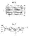
- the ends of the hose 10 may be sealed using the end fitting 200 shown in Figure 8 .
- the hose 10 has not been shown, in order to improve the clarity.
- the end fitting 200 comprises a tubular inner member 202 having a hose end 202 a and a tail end 202 b .
- the end fitting 200 further includes a sealing member which comprises a PTFE sealing ring 204 and a stainless steel split ring 206 around the PTFE sealing ring 204.
- the end fitting 200 further includes a load transferring means comprises a hose engaging member 208, a load transferring member 210 and an end member in the form of a disk-shaped plate 212.
- the load transferring member comprises a disk-shaped plate 214 and at least one load transferring rod 216. In figure 2 there are two of the rods 216, but it is possible to provide three or more of the rods 216.
- a tightening nut 218 is provided on each rod 216.
- the plates 212 and 214 have apertures 212 a and 214 a respectively for receiving the rods 216.
- the plates 212 and 214 may each be a Simonplate, the hose engaging member 202 may be a Gedring and the split ring 206 may be an Ericring.
- the plate 212 is further provided with apertures 212 b , and the tail end 202 b of the inner member 202 is provided with apertures 202 c .
- Fixing bolts 220 extend through the apertures 202 b and 212 b to secure the plate 212 to the tail end 202 a of the inner member 202.
- there are two fixing bolts 220 and associated apertures but it will be appreciated that fewer, or more, fixing bolts 220 and associated apertures could be provided.
- the hose engaging member 208 is provided with an inner helical recess in the form of grooves 208 a which are adapted to receive the outer wire 24 of the hose 10 therein.
- the inner member 202 is provided with an outer helical recess in the form of grooves 202 d which are adapted to receive the inner wire 22 therein. It will be seen from Figure 2 that, like the inner and outer wires 22 and 24, the grooves 208 a and 202 d are spaced by half a pitch length p.
- the inner member 202 is provided with two circumferential projections 202 e which are located under the sealing ring 204.
- the projections 202 e serve the improve the sealing of the tubular member 20 between the inner member 202 and the sealing ring 204, and help to prevent the tubular member from inadvertently being pulled out of position.
- the hose 10 is secured to the end fitting 200 as follows.
- the inner member 202 is threaded into the end of the hose 10, so that the hose 10 lies close to the plate 212.
- the inner wire 22 is received in the grooves 202 d and the outer wire 24 is received in the grooves 208 a .
- the inner and outer wires 22 and 24 are cut back so that they do not extend along the inner member 202 beyond the grooves 202 d and 208 a .
- the insulation 26 is also cut back to this point.
- the inner reinforcing layer 14 is also cut back at this point, or at some point before the inner reinforcing layer 14 reaches the sealing ring 204. This means that the sealing layer 18 directly engages the outer surface of the inner member 202.
- the rest of the tubular body 12, however, is allowed to extend along the inner member 202 between the inner member 202 and the sealing ring 204.
- the hose engaging member 208 is then tightened to cause it to clamp down on the hose 10 bring it into firm engagement with the hose 10.
- the nuts 218 are then tightened, which induces some axial tension in the hose 10, thereby taking up any play in the system.
- These forces are transmitted from the hose engaging member 208, to the plate 214, to the rod 216, to the plate 212, and to the tail end 202 b of the inner member 202.
- the tubular member 20 is pulled back over the upper surface of the hose engaging member 208, and is secured to projections 208b extending from the upper surface of the hose engaging member 208.
- the tubular body 12 extends under the sealing ring 204. After the hose engaging member 208 and the nuts 218 have been tightened, the split ring 206 is tightened in order to increase the force applied on the tubular body 12 by the sealing ring 204.
- the end fitting 200 is then cooled to a low temperature by liquid nitrogen. This causes the sealing ring 204 to contract relatively more than the split ring 206, whereby the compressive force applied on the sealing ring 204 by the split ring 206 is reduced. While the split ring 206 and the sealing ring 204 are at a relatively low temperature, the split ring 206 is again tightened. The temperature is then allowed to rise to ambient conditions, whereby the compressive force on the sealing ring increases by virtue of the greater expansion of sealing ring 204 relative to the split ring 206.
- the hose engaging member 208 provides some sealing of the end of the hose 208, and helps to take axial forces in the hose 10 around the sealing ring 204.
- the sealing ring 204 provides the remainder of the sealing of the hose 10.
- FIGs 5A to 5D show three applications for the hose 10.
- a floating production, storage and offloading vessel (FPSO) 102 is linked to a LNG carrier 104 by means of a hose 10 according to the invention.
- the hose 10 carries LNG from a storage tank of the FPSO 102 to a storage tank of the LNG carrier 104.
- the hose 10 lies above the sea level 106.
- the hose 10 is submerged below the sea level 106.
- the hose 10 floats near the surface of the sea.
- the LNG carrier is linked to a land-based storage facility 108 via the hose 10.
- the hose 10 may be used for many other applications apart from the applications shown in figures 5A to 5C .
- the hose may be used in cryogenic and non-cryogenic conditions.
- the tubular sheath 20 could be located outside the outer wire 24.
- the hose 10 may include additional reinforcing layers 14,18, sealing layers 16 and/or tubular sheaths 20.
- One or more of, or even all of, the sealing layers 18a may be a polymer coated metallic film, or metallised polymer film.
- one or more of, or even all of, the sealing layers 18b may be a polymer coated metallic film or metallised polymer film.
Claims (18)
- Endanschlußstück (200) zum Abschließen eines Endes eines Schlauches (10), der einen röhrenförmigen Körper (12) aus einem flexiblen Material aufweist, der zwischen inneren und äußeren Greifelementen (22, 24) angeordnet ist, wobei das Endanschlußstück aufweist: ein inneres Element (202), das angepasst ist, zumindest teilweise innerhalb des Schlauches angeordnet zu sein; ein Dichtungselement (204, 206), das angepasst ist, zumindest einen Teil des röhrenförmigen Körpers zwischen dem Dichtungselement und dem inneren Element vollständig um seinen Umfang abzudichten; und eine abtrennbare Lastübertragungseinrichtung (208, 210, 212), die angepasst ist, axiale Lasten, die auf den Schlauch angewendet werden, um das Dichtungselement herum zu übertragen, um die axiale Last auf den Schlauch zwischen dem Dichtungselement und dem inneren Element zu reduzieren oder zu beseitigen, dadurch gekennzeichnet, daß das Dichtungselement einen inneren Dichtungsring (204) und einen äußeren geteilten Ring (206) aufweist, der festgezogen werden kann, um den Dichtungsring in einen Eingriff mit dem röhrenförmigen Körper und dem inneren Element zu zwingen.
- Endanschlußstück nach Anspruch 1, wobei das innere Element im wesentlichen zylinderförmig ist und der Dichtungsring angepasst ist, das innere Element darin aufzunehmen, so daß der röhrenförmige Körper zwischen die Außenoberfläche des inneren Elements und die Innenoberfläche des Dichtungsrings geklemmt werden kann.
- Endanschlußstück nach Anspruch 1 oder 2, wobei der geteilte Ring nicht rostender Stahl ist und der Dichtungsring Polytetrafluorethylen ist.
- Endanschlußstück nach einem der Ansprüche 1 bis 3, wobei die Lastübertragungseinrichtung ein Schlaucheingriffselement (208), ein Lastübertragungselement (210) und ein an dem inneren Element befestigtes Endelement (212) aufweist, wobei die Anordnung derart ist, daß das Dichtungselement zwischen dem Lastübertragungselement und dem Endelement angeordnet ist und daß das Schlaucheingriffselement und das Endelement durch das Lastübertragungselement verbunden sind.
- Endanschlußstück nach Anspruch 4, wobei das Schlaucheingriffselement angepasst ist, in einer derartigen Weise in den Schlauch einzugreifen, daß zumindest ein Teil der axialen Kräfte innerhalb des Schlauches von dem Schlauch auf das Schlaucheingriffselement übertragen wird.
- Endanschlußstück nach Anspruch 4 oder 5, wobei das Lastübertragungselement eine Lastübertragungsplatte (214) mit einer Öffnung (212b) aufweist, die angepasst ist, den Schlauch durch sie hindurch aufzunehmen, wobei die Platte eine Oberfläche hat, die mit dem Schlaucheingriffselement in Eingriff bringbar ist, wodurch Lasten von dem Schlaucheingriffselement an die Platte übertragen werden können.
- Endanschlußstück nach Anspruch 6, wobei das Lastübertragungselement ferner einen Lastübertragungsstab (216) aufweist, der zwischen der Platte und dem Endelement angeordnet ist, um Lasten von der Platte an das Endelement zu übertragen.
- Endanschlußstück nach einem der Ansprüche 1 bis 7, wobei das innere Element ein Schlauchende (202a), das angepasst ist, sich innerhalb eines Endabschnitts des Schlauches zu erstrecken, und ein von dem Schlauchende entferntes hinteres Ende (202b) hat, und wobei das Endelement auf einer Seite des Dichtungselements benachbart zu dem hinteren Ende angeordnet ist und das Schlaucheingriffselement auf der anderen Seite des Dichtungselements benachbart zu dem Schlauchende angeordnet ist.
- Endanschlußstück nach einem der Ansprüche 1 bis 8, wobei das Dichtungselement angepasst ist, unabhängig von der Anwendung axialer Lasten zwischen dem Schlauch und dem inneren Element gegen den röhrenförmigen Körper abzudichten.
- Schlauch, der einen röhrenförmigen Körper aus flexiblem Material aufweist, der zwischen einem inneren und einem äußeren spiralförmig gewickelten Draht angeordnet ist, wobei der röhrenförmige Körper dazu dient, ein Fluid durch den Schlauch zu transportieren und das Lecken von Fluid durch den Körper zu verhindern, dadurch gekennzeichnet, daß der Schlauch ferner ein Endanschlußstück nach einem der Ansprüche 1 bis 8 aufweist, das an eines seiner Enden angepaßt ist.
- Schlauch nach Anspruch 10, der abhängig von Anspruch 4 ist, wobei das Schlaucheingriffselement angepasst ist, einen Teil des Schlauches, der über einen äußeren Teil des Schlaucheingriffselements zurückgefaltet ist, zu befestigen.
- Schlauch nach Anspruch 11, der ferner eine axiale Festigungseinrichtung in der Form eines Geflechts (20) um den röhrenförmigen Körper herum aufweist, und wobei das Geflecht der Teil des Schlauches ist, der über den äußeren Teil des röhrenförmigen Elements zurückgefaltet ist.
- Schlauch nach Anspruch 10, 11 oder 12, wobei der röhrenförmige Körper sich zwischen dem inneren Element und dem Dichtungselement erstreckt.
- Schlauch nach Anspruch 10, 11, 12 oder 13, wobei der röhrenförmige Körper wenigstens eine Verstärkungslage und wenigstens eine Dichtungslage aufweist.
- Verfahren zum Herstellen eines Schlauches, das aufweist:(a) Wickeln eines Drahtes um einen röhrenförmigen Dorn zum Erzeugen einer Innenspirale;(b) Wickeln eines Schichtmaterials um den röhrenförmigen Dorn und die Innenspirale, um einen röhrenförmigen Körper bereitzustellen, der aus dem Schichtmaterial gebildet ist;(c) Wickeln eines Drahtes um den röhrenförmigen Körper zum Erzeugen einer Außenspirale; und(d) Entfernen des Schlauches von dem Dorn; gekennzeichnet durch die folgenden Schritte:(e) Anordnen eines inneren Elements in einem offenen Ende des Schlauches;(f) Klemmen einer Lastübertragungseinrichtung an eine Außenoberfläche des Schlauches; und(g) Klemmen eines Dichtungselements, das einen inneren Dichtungsring und einen äußeren geteilten Ring aufweist, an eine Außenoberfläche des röhrenförmigen Körpers und Festziehen des geteilten Rings, um den Dichtungsring in einen Eingriff mit dem röhrenförmigen Körper und dem inneren Element zu zwingen.
- Verfahren nach Anspruch 15, wobei die Lastübertragungseinrichtung dazu dient, axiale Lasten, die zwischen dem Schlauch und dem inneren Element angewendet werden, in einer derartigen Weise zu übertragen, daß diese axialen Lasten um das Dichtungselement herum verteilt werden, um jegliche axiale Last auf den Schlauch zwischen dem Dichtungselement und dem inneren Element zu verringern oder zu beseitigen, und wobei das Klemmen des Dichtungselements an die Außenoberfläche des röhrenförmigen Körpers in Schritt (g) das Dichtungselement unabhängig von der Anwendung axialer Lasten zwischen dem Schlauch und dem inneren Element gegen den röhrenförmigen Körper abdichtet.
- Verfahren nach Anspruch 15 oder 16, das ferner den folgenden Schritt zwischen (b) und (c) aufweist:(h) Ziehen eines röhrenförmigen axialen Festigungselements über ein freies Ende des Dorns, so daß der Dorn sich innerhalb des axialen Festigungselements erstreckt, dann Ziehen des axialen Festigungselements entlang des Dorns, so daß es den röhrenförmigen Körper zumindest teilweise bedeckt.
- Verfahren nach Anspruch 17, wobei die axiale Festigungseinrichtung von der Lastübertragungseinrichtung eingeklemmt wird und ferner den folgenden Schritt nach dem Schritt (f) aufweist:(i) Zurückfalten des röhrenförmigen axialen Festigungselements über einen Teil der axialen Festigungseinrichtung.
Applications Claiming Priority (10)
| Application Number | Priority Date | Filing Date | Title |
|---|---|---|---|
| GB0014353A GB2366345A (en) | 2000-06-12 | 2000-06-12 | Hose incorporating an improved sealing layer |
| GB0014352A GB0014352D0 (en) | 2000-06-12 | 2000-06-12 | End fitting for a hose |
| GB0014354A GB0014354D0 (en) | 2000-06-12 | 2000-06-12 | Hose having improved axial strength |
| GB0014355A GB2363439B (en) | 2000-06-12 | 2000-06-12 | End fitting for a hose |
| GB0014350A GB2366344B (en) | 2000-06-12 | 2000-06-12 | Hose having improved flexing capabilities |
| GB0109013A GB2366348B (en) | 2000-06-12 | 2001-04-10 | Hose incorporating an improved sealing layer |
| GB0109012A GB2366347B (en) | 2000-06-12 | 2001-04-10 | Improvements to an outer portion of a hose |
| GB0109011A GB2363440B (en) | 2000-06-12 | 2001-04-10 | End fitting for a hose |
| GB0111022A GB2368377B (en) | 2000-06-12 | 2001-05-04 | Hose having improved axial strength |
| EP01938396A EP1292790B1 (de) | 2000-06-12 | 2001-06-12 | Schlauch |
Related Parent Applications (2)
| Application Number | Title | Priority Date | Filing Date |
|---|---|---|---|
| EP01938396A Division EP1292790B1 (de) | 2000-06-12 | 2001-06-12 | Schlauch |
| EP01938396.7 Division | 2001-06-12 |
Publications (3)
| Publication Number | Publication Date |
|---|---|
| EP1677040A2 EP1677040A2 (de) | 2006-07-05 |
| EP1677040A3 EP1677040A3 (de) | 2006-11-02 |
| EP1677040B1 true EP1677040B1 (de) | 2010-08-11 |
Family
ID=27576259
Family Applications (2)
| Application Number | Title | Priority Date | Filing Date |
|---|---|---|---|
| EP01938396A Expired - Lifetime EP1292790B1 (de) | 2000-06-12 | 2001-06-12 | Schlauch |
| EP06075084A Expired - Lifetime EP1677040B1 (de) | 2000-06-12 | 2001-06-12 | Schlauchkupplung |
Family Applications Before (1)
| Application Number | Title | Priority Date | Filing Date |
|---|---|---|---|
| EP01938396A Expired - Lifetime EP1292790B1 (de) | 2000-06-12 | 2001-06-12 | Schlauch |
Country Status (13)
| Country | Link |
|---|---|
| US (3) | US7243686B2 (de) |
| EP (2) | EP1292790B1 (de) |
| CN (1) | CN1249369C (de) |
| AT (2) | ATE477448T1 (de) |
| AU (4) | AU2001264075B2 (de) |
| BR (1) | BR0111629B1 (de) |
| CA (2) | CA2411113C (de) |
| DE (2) | DE60142805D1 (de) |
| EA (1) | EA005484B1 (de) |
| ES (1) | ES2257413T3 (de) |
| NO (1) | NO335227B1 (de) |
| SG (1) | SG144732A1 (de) |
| WO (1) | WO2001096772A1 (de) |
Families Citing this family (48)
| Publication number | Priority date | Publication date | Assignee | Title |
|---|---|---|---|---|
| WO2004079248A1 (en) * | 2003-03-05 | 2004-09-16 | Bhp Billiton Petroleum Pty Ltd | Hose end fitting |
| GB0226271D0 (en) * | 2002-11-11 | 2002-12-18 | Bhp Billiton Petroleum Pty Ltd | Improvements relating to hose |
| US6926037B2 (en) * | 2002-12-17 | 2005-08-09 | Wellstream International Limited | Collapse tolerant flexible pipe and method of manufacturing same |
| US20100139661A1 (en) * | 2003-12-18 | 2010-06-10 | Scott Technologies, Inc. | Air breathing hose with integrated electrical wiring |
| US7588056B2 (en) * | 2005-03-14 | 2009-09-15 | Ansul Canada Limited | Methods and systems for enhanced fluid transport |
| EP1731823A1 (de) * | 2005-06-08 | 2006-12-13 | Single Buoy Moorings Inc. | Schlauch zum Befördern von kryogenen Fluiden |
| CA2631617A1 (en) * | 2005-11-30 | 2007-06-07 | Parker-Hannifin Corporation | High temperature thermoplastic power steering hose |
| BRPI0710424A2 (pt) * | 2006-05-08 | 2011-08-09 | Bhp Billiton Petroleum Pty Ltd | mangueira, uso de uma mangueira , método para fabricar mangueira e aparelho |
| GB0609079D0 (en) * | 2006-05-08 | 2006-06-21 | Bhp Billiton Petroleum Pty Ltd | Improvements relating to hose |
| SG171661A1 (en) * | 2006-05-08 | 2011-06-29 | Bhp Billiton Petroleum Pty Ltd | Improvements relating to hose |
| EP1855040A1 (de) * | 2006-05-08 | 2007-11-14 | BHP Billiton Innovation Pty Ltd | Schläuchebetreffende Verbesserungen |
| GB0611977D0 (en) | 2006-06-16 | 2006-07-26 | Wellstream Int Ltd | Radius control |
| GB0612991D0 (en) * | 2006-06-29 | 2006-08-09 | Bhp Billiton Petroleum Pty Ltd | Improvements relating to hose |
| GB0616054D0 (en) * | 2006-08-11 | 2006-09-20 | Bhp Billiton Petroleum Pty Ltd | Improvements relating to hose |
| GB0616052D0 (en) | 2006-08-11 | 2006-09-20 | Bhp Billiton Petroleum Pty Ltd | Improvements relating to hose |
| GB0616053D0 (en) | 2006-08-11 | 2006-09-20 | Bhp Billiton Petroleum Pty Ltd | Improvements relating to hose |
| DE102006054471B4 (de) * | 2006-11-18 | 2018-10-31 | Fischerwerke Gmbh & Co. Kg | Verwendung eines feinverteilte Gase beinhaltenden Mehrkomponenten-Kunstsharzsystems zur Befestigung von Befestigungselementen |
| MY151397A (en) | 2006-12-11 | 2014-05-30 | Trelleborg Ind Sas | Cryogenic transfer hose having a fibrous insulating layer and method of constructing such a transfer hose |
| ES2424134T3 (es) * | 2007-09-14 | 2013-09-27 | Bhp Billiton Petroleum Pty Ltd | Mejoras relacionadas con elementos de conexión de tubo flexible |
| AU2009237716B2 (en) * | 2008-04-15 | 2014-05-29 | Trelleborg Industrie Sas | Fluid-tight end fitting for a composite hose and method of assembling a composite hose on such end fitting |
| JP5592078B2 (ja) * | 2008-04-28 | 2014-09-17 | タイガースポリマー株式会社 | 断熱ホース及びその製造方法 |
| EP2352785B1 (de) * | 2008-10-03 | 2018-08-22 | Uponor Innovation AB | Verfahren und zusammensetzungen zum beschichten von rohren |
| US8047577B2 (en) * | 2008-10-27 | 2011-11-01 | All-American Hose Llc | Hose coupling |
| US8479777B2 (en) * | 2008-11-21 | 2013-07-09 | Parker-Hannifin Corporation | Low temperature, high pressure rubber hose |
| EP2230433A3 (de) | 2009-03-16 | 2011-09-14 | BPP Technical Services Ltd. | Schlauch |
| GB0904498D0 (en) | 2009-03-16 | 2009-04-29 | Bpp Technical Services Ltd | Hose end fitting |
| US9441766B2 (en) | 2009-06-02 | 2016-09-13 | Bhp Billiton Petroleum Pty Ltd. | Reinforced hose |
| CN101780720B (zh) * | 2010-03-15 | 2012-12-12 | 义乌市金佐消防水带厂 | 三元乙丙消防水带的生产方法 |
| IT1399509B1 (it) * | 2010-04-22 | 2013-04-19 | Ind Plastiche Lombarde S P A | "dispositivo di fissaggio per tubi in materia plastica flessibili" |
| US20110284116A1 (en) * | 2010-05-20 | 2011-11-24 | Novaflex Hose Inc. | High-temperature flexible composite hose |
| FR2963817B1 (fr) | 2010-08-16 | 2013-10-18 | Technip France | Embout de connexion d'une conduite flexible de transport d'un fluide cryogenique. |
| JP5643073B2 (ja) | 2010-12-10 | 2014-12-17 | 矢崎総業株式会社 | ワイヤハーネス及びワイヤハーネスの製造方法 |
| JP5638939B2 (ja) * | 2010-12-28 | 2014-12-10 | 矢崎総業株式会社 | ワイヤハーネス及びワイヤハーネスの製造方法 |
| JP5643080B2 (ja) | 2010-12-28 | 2014-12-17 | 矢崎総業株式会社 | ワイヤハーネス及びワイヤハーネスの製造方法 |
| JP5638937B2 (ja) * | 2010-12-28 | 2014-12-10 | 矢崎総業株式会社 | ワイヤハーネス及びワイヤハーネスの製造方法 |
| US8393436B2 (en) * | 2011-04-15 | 2013-03-12 | Arrowhead Products Corporation | Flexible muffler for use in aircraft environmental control systems and method of manufacture |
| US20120273083A1 (en) * | 2011-04-27 | 2012-11-01 | Ting-I Lin | Hose assembly |
| CA2775538A1 (en) * | 2011-04-28 | 2012-10-28 | Steve Ialenti | Protective cut-resistant sportswear material |
| GB201109876D0 (en) | 2011-06-13 | 2011-07-27 | Oceaneering Internat Services Ltd | Umbilical hose with improved ovalisation resistance |
| US8910669B2 (en) | 2012-02-23 | 2014-12-16 | Ticona Llc | Insert for pipe assembly and method for forming pipe assembly |
| FR2994242B1 (fr) | 2012-08-03 | 2015-03-06 | Technip France | Conduite flexible sous marine comprenant une gaine polymerique interne et/ou externe d'etancheite comprenant un polyethylene a haut poids moleculaire |
| DE102014206508A1 (de) * | 2014-04-04 | 2015-10-08 | Msa Europe Gmbh | Schlauchvorrichtung für ein Atemschutzgerät |
| CN104385647B (zh) * | 2014-08-22 | 2017-12-15 | 五行科技股份有限公司 | 低延伸率多层软管及其制造方法 |
| CN104385648A (zh) * | 2014-08-22 | 2015-03-04 | 五行材料科技(江苏)有限公司 | 多层软管的制造方法 |
| CN104879733A (zh) * | 2015-06-05 | 2015-09-02 | 广东佳明电器有限公司 | 一种蒸汽发生器的改进结构 |
| CN106764122B (zh) * | 2016-12-20 | 2018-12-14 | 湘潭新奥燃气发展有限公司 | 一种市政燃气管 |
| US11140890B2 (en) | 2019-08-21 | 2021-10-12 | Cnh Industrial America Llc | Agricultural vehicle having an improved application boom with a composite tube |
| RU2733779C1 (ru) * | 2019-11-11 | 2020-10-06 | Федеральное государственное унитарное предприятие "Всероссийский научно-исследовательский институт авиационных материалов" (ФГУП "ВИАМ") | Тканепленочный материал и изделие на его основе |
Family Cites Families (64)
| Publication number | Priority date | Publication date | Assignee | Title |
|---|---|---|---|---|
| GB591307A (en) | 1945-11-14 | 1947-08-13 | Compoflex Co Ltd | Improvements in or relating to flexible tubing |
| US956076A (en) * | 1906-10-30 | 1910-04-26 | Edwin T Greenfield | Coupling. |
| US1178559A (en) * | 1915-12-30 | 1916-04-11 | John J Vautier | Gas-tubing. |
| US1588606A (en) * | 1922-02-16 | 1926-06-15 | John M Oden | Method of making coupling sleeves |
| US1599775A (en) * | 1924-11-03 | 1926-09-14 | West American Rubber Company | Rotary hose coupling |
| GB323352A (en) * | 1928-12-15 | 1930-01-02 | Leyland & Birmingham Rubber Co | Improvements in or relating to pipe couplings |
| US1901330A (en) * | 1930-03-20 | 1933-03-14 | Superflexit | Fluid-conductive hose |
| US1911486A (en) * | 1931-04-09 | 1933-05-30 | Standard Oil Co | Hose coupler |
| US1810032A (en) * | 1931-04-16 | 1931-06-16 | Schulthess Ernest | Oil hose |
| US2011781A (en) * | 1933-08-24 | 1935-08-20 | Tabozzi Giacinto | Flexible pipe for oil, essence, and the like, especially for aerial machines |
| US2184984A (en) * | 1938-08-12 | 1939-12-26 | Clifford E Van Stone | High pressure hose |
| GB519307A (en) | 1938-09-15 | 1940-03-21 | Martin Robert | Improvements in or relating to machines for pressing fabrics |
| GB550543A (en) | 1941-08-14 | 1943-01-13 | Compoflex Co Ltd | Improvements in or relating to flexible tubing |
| US2371363A (en) * | 1944-02-08 | 1945-03-13 | Walter G L Smith | Hose connector |
| US2661026A (en) * | 1948-11-09 | 1953-12-01 | Schulthess Ernest | Oil hose |
| FR1041160A (fr) * | 1950-12-11 | 1953-10-21 | Neue Argus Gmbh | Raccord vissé pour un tuyau en caoutchouc portant un guipage ou une garniture intérieure en produit textile ou en fils métalliques |
| GB741643A (en) | 1953-10-29 | 1955-12-07 | Compoflex Co Ltd | Improvements in couplings for flexible hose |
| US2829671A (en) * | 1954-07-15 | 1958-04-08 | Us Rubber Co | Reinforced hose |
| FR1161980A (fr) * | 1956-04-25 | 1958-09-08 | Neue Argus Gmbh | Raccord pour un tuyau souple en caoutchouc ou en matière synthétique de grand diamètre, et procédé de fixation de ce raccord sur le tuyau |
| BE574487A (de) | 1958-01-07 | |||
| GB850131A (en) | 1958-06-13 | 1960-09-28 | Cyril Austin | Improvements in or relating to couplings or end fittings for flexible conduits |
| GB895553A (en) | 1960-02-24 | 1962-05-02 | Union Carbide Corp | Improvements in and relating to hoses for liquid |
| US3189370A (en) * | 1962-07-13 | 1965-06-15 | Dixon Valve & Coupling Co | Hose coupling connection for wire reinforced elastomeric cables |
| DE1425453A1 (de) * | 1962-08-02 | 1969-07-10 | Continental Gummi Werke Ag | Druck- und/oder Saugschlauch |
| GB1034956A (en) | 1964-06-10 | 1966-07-06 | Superflexit | Improvements in flexible electric conduits or hoses |
| FR1586545A (de) * | 1968-10-23 | 1970-02-20 | ||
| GB1383313A (en) | 1971-05-21 | 1974-02-12 | Compoflex Co Ltd | Flexible tubing or hoses |
| USRE28155E (en) * | 1973-06-18 | 1974-09-10 | Triaxial fabric | |
| AU7028574A (en) | 1973-06-29 | 1976-01-08 | Dunlop Australia Ltd | Hose pipes |
| US4091063A (en) | 1974-07-11 | 1978-05-23 | Dayco Corporation | Hose construction and method of making same |
| DE2541242A1 (de) * | 1975-09-12 | 1977-03-24 | Kabel Metallwerke Ghh | Armatur fuer eine wellrohrleitung |
| JPS5560788A (en) * | 1978-10-31 | 1980-05-08 | Bridgestone Tire Co Ltd | Hose end structure |
| NL177759B (nl) | 1979-06-27 | 1985-06-17 | Stamicarbon | Werkwijze ter vervaardiging van een polyetheendraad, en de aldus verkregen polyetheendraad. |
| IT1124638B (it) | 1979-10-24 | 1986-05-07 | Pirelli | Condotto termoisolato |
| US4330143A (en) * | 1979-12-03 | 1982-05-18 | Reneau Bobby J | Apparatus for connecting together flowline end portions |
| JPS57198329A (en) | 1981-05-30 | 1982-12-04 | Nippon Denso Co Ltd | Opening and closing device of intake air throttle valve for internal combustion engine |
| GB2104996B (en) * | 1981-08-28 | 1985-06-19 | Ti Flexible Tubes Ltd | Hose |
| GB2104992B (en) * | 1981-08-28 | 1985-07-24 | Ti Flexible Tubes Ltd | Hose end fitting |
| GB2107819B (en) | 1981-10-02 | 1985-01-23 | Shell Res Ltd | Flexible hose for liquefied gases |
| NL8104728A (nl) | 1981-10-17 | 1983-05-16 | Stamicarbon | Werkwijze voor het vervaardigen van polyetheen filamenten met grote treksterkte. |
| EP0183285B1 (de) | 1984-09-28 | 1990-04-11 | Stamicarbon B.V. | Verfahren zur kontinuierlichen Herstellung von homogenen Lösungen von hochmolekularen Polymeren |
| DE3440459A1 (de) * | 1984-11-06 | 1986-05-07 | Phoenix Ag, 2100 Hamburg | Folienschlauch |
| NL8502298A (nl) | 1985-08-21 | 1987-03-16 | Stamicarbon | Werkwijze voor het vervaardigen van polyethyleenvoorwerpen met hoge treksterkte en modulus. |
| US4634153A (en) * | 1985-09-03 | 1987-01-06 | Hydrafit, Inc. | Reusable hose fitting |
| US4876049A (en) * | 1985-11-21 | 1989-10-24 | Nippon Petrochemicals Co., Ltd. | Method for preparing molded articles of ultra-high molecular weight polyethylene |
| JPS62130286U (de) | 1986-02-07 | 1987-08-17 | ||
| CH671443A5 (de) | 1986-10-13 | 1989-08-31 | Fischer Ag Georg | |
| US4950001A (en) * | 1987-12-11 | 1990-08-21 | Simplex Wire & Cable | Graduated friction anchor |
| US5182147A (en) | 1988-10-14 | 1993-01-26 | Dantec Ltd. | Composite hose |
| NL8903178A (nl) | 1989-12-29 | 1991-07-16 | Stamicarbon | Werkwijze voor het onderling hechten van lagen ultra-hoog moleculair polyethyleen. |
| DE4411221A1 (de) * | 1994-03-31 | 1995-10-05 | Hilti Ag | Rohrschellenverschluss |
| JP3556278B2 (ja) * | 1994-07-15 | 2004-08-18 | 株式会社明治フレックス | コンポジットホース |
| US5485870A (en) | 1994-12-05 | 1996-01-23 | Kraik; Newell P. | Wire wrapped composite spiral hose and method |
| US5480193A (en) | 1995-05-22 | 1996-01-02 | Echols; Joseph A. | Clamp for push-on couplings |
| US5685576A (en) * | 1995-06-06 | 1997-11-11 | Wolfe; Donald H. | Pipe coupling |
| US5639128A (en) * | 1995-06-21 | 1997-06-17 | Wellstream, Inc. | Method of and apparatus for securing a multi-layered flexible flowline to an end fitting |
| US6012496A (en) * | 1996-01-29 | 2000-01-11 | Hybritech Polymers | Multi-layer tubing assembly for fluid and vapor handling systems |
| US5698278A (en) * | 1996-09-20 | 1997-12-16 | The Goodyear Tire & Rubber Company | Smooth bore hot tar and asphalt hose |
| FR2758588B1 (fr) * | 1997-01-23 | 1999-02-19 | Hutchinson | Flexible de decouplage monte dans une ligne d'echappement d'un moteur de vehicule automobile |
| US6074717A (en) | 1997-07-29 | 2000-06-13 | Dayco Products, Inc. | Flexible hose having an aluminum barrier layer to prevent ingestion of oxygen |
| JPH11325333A (ja) | 1998-05-18 | 1999-11-26 | Meiji Flex:Kk | コンポジットホース |
| JP3482515B2 (ja) * | 1998-08-28 | 2003-12-22 | 東拓工業株式会社 | 管端連結継手 |
| US6334466B1 (en) * | 1998-10-09 | 2002-01-01 | The Gates Corporation | Abrasion-resistant material handling hose |
| FR2816389B1 (fr) * | 2000-11-08 | 2003-05-30 | Coflexip | Embout pour conduite flexible |
-
2001
- 2001-06-12 AU AU2001264075A patent/AU2001264075B2/en not_active Ceased
- 2001-06-12 SG SG200501410-5A patent/SG144732A1/en unknown
- 2001-06-12 US US10/311,399 patent/US7243686B2/en not_active Expired - Lifetime
- 2001-06-12 AU AU6407501A patent/AU6407501A/xx active Pending
- 2001-06-12 CA CA002411113A patent/CA2411113C/en not_active Expired - Fee Related
- 2001-06-12 AT AT06075084T patent/ATE477448T1/de not_active IP Right Cessation
- 2001-06-12 BR BRPI0111629-0A patent/BR0111629B1/pt not_active IP Right Cessation
- 2001-06-12 ES ES01938396T patent/ES2257413T3/es not_active Expired - Lifetime
- 2001-06-12 EA EA200300016A patent/EA005484B1/ru not_active IP Right Cessation
- 2001-06-12 EP EP01938396A patent/EP1292790B1/de not_active Expired - Lifetime
- 2001-06-12 DE DE60142805T patent/DE60142805D1/de not_active Expired - Lifetime
- 2001-06-12 CN CNB018127371A patent/CN1249369C/zh not_active Expired - Fee Related
- 2001-06-12 DE DE60116759T patent/DE60116759T2/de not_active Expired - Lifetime
- 2001-06-12 CA CA2684456A patent/CA2684456C/en not_active Expired - Fee Related
- 2001-06-12 WO PCT/GB2001/002562 patent/WO2001096772A1/en active IP Right Grant
- 2001-06-12 AT AT01938396T patent/ATE316220T1/de not_active IP Right Cessation
- 2001-06-12 EP EP06075084A patent/EP1677040B1/de not_active Expired - Lifetime
-
2002
- 2002-12-09 NO NO20025899A patent/NO335227B1/no not_active IP Right Cessation
-
2006
- 2006-06-27 US US11/426,613 patent/US7712792B2/en not_active Expired - Fee Related
- 2006-06-27 US US11/426,615 patent/US7743792B2/en not_active Expired - Fee Related
-
2007
- 2007-02-02 AU AU2007200461A patent/AU2007200461A1/en not_active Abandoned
-
2011
- 2011-02-25 AU AU2011200833A patent/AU2011200833B2/en not_active Ceased
Also Published As
Similar Documents
| Publication | Publication Date | Title |
|---|---|---|
| EP1677040B1 (de) | Schlauchkupplung | |
| CA2651575C (en) | Improvements relating to hose | |
| AU2001264075A1 (en) | Improvements relating to hose | |
| US7735524B2 (en) | Hose | |
| EP2057395B1 (de) | Verstärkter schlauch | |
| JP5744701B2 (ja) | ホース | |
| WO2008001114A1 (en) | Axially reinforced hose | |
| US9441766B2 (en) | Reinforced hose | |
| GB2368377A (en) | Hose having improved axial strength | |
| AU2007200462B2 (en) | Improvements relating to hose |
Legal Events
| Date | Code | Title | Description |
|---|---|---|---|
| PUAI | Public reference made under article 153(3) epc to a published international application that has entered the european phase |
Free format text: ORIGINAL CODE: 0009012 |
|
| AC | Divisional application: reference to earlier application |
Ref document number: 1292790 Country of ref document: EP Kind code of ref document: P |
|
| AK | Designated contracting states |
Kind code of ref document: A2 Designated state(s): AT BE CH CY DE DK ES FI FR GB GR IE IT LI LU MC NL PT SE TR |
|
| RIN1 | Information on inventor provided before grant (corrected) |
Inventor name: THORP, SIMON PETER ALEXANDER Inventor name: DAVIS, ERIC JOSEPH Inventor name: WITZ, JOEL ARON Inventor name: RIDOLFI, MATTHEW VERNON Inventor name: BURKE, RAYMOND NICHOLAS Inventor name: HALL, GERARD ANTHONY |
|
| PUAL | Search report despatched |
Free format text: ORIGINAL CODE: 0009013 |
|
| AK | Designated contracting states |
Kind code of ref document: A3 Designated state(s): AT BE CH CY DE DK ES FI FR GB GR IE IT LI LU MC NL PT SE TR |
|
| AKX | Designation fees paid | ||
| 17P | Request for examination filed |
Effective date: 20070420 |
|
| RBV | Designated contracting states (corrected) |
Designated state(s): AT BE CH CY DE DK ES FI FR GB GR IE IT LI LU MC NL PT SE TR |
|
| REG | Reference to a national code |
Ref country code: DE Ref legal event code: 8566 |
|
| D17P | Request for examination filed (deleted) | ||
| 17Q | First examination report despatched |
Effective date: 20070808 |
|
| R17P | Request for examination filed (corrected) |
Effective date: 20070724 |
|
| RBV | Designated contracting states (corrected) |
Designated state(s): AT BE CH CY DE DK ES FI FR GB GR IE IT LI LU MC NL PT SE TR |
|
| R17P | Request for examination filed (corrected) |
Effective date: 20070720 |
|
| RBV | Designated contracting states (corrected) |
Designated state(s): AT BE CH CY DE DK ES FI FR GB GR IE IT LI LU MC NL PT SE TR |
|
| GRAP | Despatch of communication of intention to grant a patent |
Free format text: ORIGINAL CODE: EPIDOSNIGR1 |
|
| GRAS | Grant fee paid |
Free format text: ORIGINAL CODE: EPIDOSNIGR3 |
|
| GRAA | (expected) grant |
Free format text: ORIGINAL CODE: 0009210 |
|
| AC | Divisional application: reference to earlier application |
Ref document number: 1292790 Country of ref document: EP Kind code of ref document: P |
|
| AK | Designated contracting states |
Kind code of ref document: B1 Designated state(s): AT BE CH CY DE DK ES FI FR GB GR IE IT LI LU MC NL PT SE TR |
|
| REG | Reference to a national code |
Ref country code: GB Ref legal event code: FG4D |
|
| REG | Reference to a national code |
Ref country code: CH Ref legal event code: EP |
|
| REG | Reference to a national code |
Ref country code: IE Ref legal event code: FG4D |
|
| REF | Corresponds to: |
Ref document number: 60142805 Country of ref document: DE Date of ref document: 20100923 Kind code of ref document: P |
|
| REG | Reference to a national code |
Ref country code: NL Ref legal event code: T3 |
|
| PG25 | Lapsed in a contracting state [announced via postgrant information from national office to epo] |
Ref country code: FI Free format text: LAPSE BECAUSE OF FAILURE TO SUBMIT A TRANSLATION OF THE DESCRIPTION OR TO PAY THE FEE WITHIN THE PRESCRIBED TIME-LIMIT Effective date: 20100811 Ref country code: AT Free format text: LAPSE BECAUSE OF FAILURE TO SUBMIT A TRANSLATION OF THE DESCRIPTION OR TO PAY THE FEE WITHIN THE PRESCRIBED TIME-LIMIT Effective date: 20100811 |
|
| REG | Reference to a national code |
Ref country code: ES Ref legal event code: FG2A Effective date: 20110126 |
|
| PG25 | Lapsed in a contracting state [announced via postgrant information from national office to epo] |
Ref country code: CY Free format text: LAPSE BECAUSE OF FAILURE TO SUBMIT A TRANSLATION OF THE DESCRIPTION OR TO PAY THE FEE WITHIN THE PRESCRIBED TIME-LIMIT Effective date: 20100811 Ref country code: PT Free format text: LAPSE BECAUSE OF FAILURE TO SUBMIT A TRANSLATION OF THE DESCRIPTION OR TO PAY THE FEE WITHIN THE PRESCRIBED TIME-LIMIT Effective date: 20101213 |
|
| PG25 | Lapsed in a contracting state [announced via postgrant information from national office to epo] |
Ref country code: SE Free format text: LAPSE BECAUSE OF FAILURE TO SUBMIT A TRANSLATION OF THE DESCRIPTION OR TO PAY THE FEE WITHIN THE PRESCRIBED TIME-LIMIT Effective date: 20100811 Ref country code: GR Free format text: LAPSE BECAUSE OF FAILURE TO SUBMIT A TRANSLATION OF THE DESCRIPTION OR TO PAY THE FEE WITHIN THE PRESCRIBED TIME-LIMIT Effective date: 20101112 Ref country code: BE Free format text: LAPSE BECAUSE OF FAILURE TO SUBMIT A TRANSLATION OF THE DESCRIPTION OR TO PAY THE FEE WITHIN THE PRESCRIBED TIME-LIMIT Effective date: 20100811 |
|
| PG25 | Lapsed in a contracting state [announced via postgrant information from national office to epo] |
Ref country code: DK Free format text: LAPSE BECAUSE OF FAILURE TO SUBMIT A TRANSLATION OF THE DESCRIPTION OR TO PAY THE FEE WITHIN THE PRESCRIBED TIME-LIMIT Effective date: 20100811 |
|
| PLBE | No opposition filed within time limit |
Free format text: ORIGINAL CODE: 0009261 |
|
| STAA | Information on the status of an ep patent application or granted ep patent |
Free format text: STATUS: NO OPPOSITION FILED WITHIN TIME LIMIT |
|
| 26N | No opposition filed |
Effective date: 20110512 |
|
| REG | Reference to a national code |
Ref country code: DE Ref legal event code: R097 Ref document number: 60142805 Country of ref document: DE Effective date: 20110512 |
|
| REG | Reference to a national code |
Ref country code: CH Ref legal event code: PL |
|
| REG | Reference to a national code |
Ref country code: IE Ref legal event code: MM4A |
|
| PG25 | Lapsed in a contracting state [announced via postgrant information from national office to epo] |
Ref country code: IE Free format text: LAPSE BECAUSE OF NON-PAYMENT OF DUE FEES Effective date: 20110612 Ref country code: LI Free format text: LAPSE BECAUSE OF NON-PAYMENT OF DUE FEES Effective date: 20110630 Ref country code: CH Free format text: LAPSE BECAUSE OF NON-PAYMENT OF DUE FEES Effective date: 20110630 |
|
| PG25 | Lapsed in a contracting state [announced via postgrant information from national office to epo] |
Ref country code: MC Free format text: LAPSE BECAUSE OF NON-PAYMENT OF DUE FEES Effective date: 20110630 |
|
| PG25 | Lapsed in a contracting state [announced via postgrant information from national office to epo] |
Ref country code: LU Free format text: LAPSE BECAUSE OF NON-PAYMENT OF DUE FEES Effective date: 20110612 |
|
| PG25 | Lapsed in a contracting state [announced via postgrant information from national office to epo] |
Ref country code: TR Free format text: LAPSE BECAUSE OF FAILURE TO SUBMIT A TRANSLATION OF THE DESCRIPTION OR TO PAY THE FEE WITHIN THE PRESCRIBED TIME-LIMIT Effective date: 20100811 |
|
| REG | Reference to a national code |
Ref country code: FR Ref legal event code: PLFP Year of fee payment: 15 |
|
| REG | Reference to a national code |
Ref country code: FR Ref legal event code: PLFP Year of fee payment: 16 |
|
| PGFP | Annual fee paid to national office [announced via postgrant information from national office to epo] |
Ref country code: GB Payment date: 20160608 Year of fee payment: 16 Ref country code: DE Payment date: 20160607 Year of fee payment: 16 Ref country code: ES Payment date: 20160527 Year of fee payment: 16 |
|
| PGFP | Annual fee paid to national office [announced via postgrant information from national office to epo] |
Ref country code: FR Payment date: 20160526 Year of fee payment: 16 Ref country code: NL Payment date: 20160610 Year of fee payment: 16 |
|
| PGFP | Annual fee paid to national office [announced via postgrant information from national office to epo] |
Ref country code: IT Payment date: 20160621 Year of fee payment: 16 |
|
| REG | Reference to a national code |
Ref country code: DE Ref legal event code: R119 Ref document number: 60142805 Country of ref document: DE |
|
| REG | Reference to a national code |
Ref country code: NL Ref legal event code: MM Effective date: 20170701 |
|
| GBPC | Gb: european patent ceased through non-payment of renewal fee |
Effective date: 20170612 |
|
| PG25 | Lapsed in a contracting state [announced via postgrant information from national office to epo] |
Ref country code: NL Free format text: LAPSE BECAUSE OF NON-PAYMENT OF DUE FEES Effective date: 20170701 |
|
| REG | Reference to a national code |
Ref country code: FR Ref legal event code: ST Effective date: 20180228 |
|
| PG25 | Lapsed in a contracting state [announced via postgrant information from national office to epo] |
Ref country code: DE Free format text: LAPSE BECAUSE OF NON-PAYMENT OF DUE FEES Effective date: 20180103 Ref country code: GB Free format text: LAPSE BECAUSE OF NON-PAYMENT OF DUE FEES Effective date: 20170612 |
|
| PG25 | Lapsed in a contracting state [announced via postgrant information from national office to epo] |
Ref country code: FR Free format text: LAPSE BECAUSE OF NON-PAYMENT OF DUE FEES Effective date: 20170630 Ref country code: IT Free format text: LAPSE BECAUSE OF NON-PAYMENT OF DUE FEES Effective date: 20170612 |
|
| REG | Reference to a national code |
Ref country code: ES Ref legal event code: FD2A Effective date: 20181107 |
|
| PG25 | Lapsed in a contracting state [announced via postgrant information from national office to epo] |
Ref country code: ES Free format text: LAPSE BECAUSE OF NON-PAYMENT OF DUE FEES Effective date: 20170613 |