EP1672954A2 - Dispositif et procédé destiné à la saisie d'affichages de compteurs - Google Patents
Dispositif et procédé destiné à la saisie d'affichages de compteurs Download PDFInfo
- Publication number
- EP1672954A2 EP1672954A2 EP05077742A EP05077742A EP1672954A2 EP 1672954 A2 EP1672954 A2 EP 1672954A2 EP 05077742 A EP05077742 A EP 05077742A EP 05077742 A EP05077742 A EP 05077742A EP 1672954 A2 EP1672954 A2 EP 1672954A2
- Authority
- EP
- European Patent Office
- Prior art keywords
- data
- counter
- data collector
- received
- radio
- Prior art date
- Legal status (The legal status is an assumption and is not a legal conclusion. Google has not performed a legal analysis and makes no representation as to the accuracy of the status listed.)
- Granted
Links
Images
Classifications
-
- G—PHYSICS
- G01—MEASURING; TESTING
- G01D—MEASURING NOT SPECIALLY ADAPTED FOR A SPECIFIC VARIABLE; ARRANGEMENTS FOR MEASURING TWO OR MORE VARIABLES NOT COVERED IN A SINGLE OTHER SUBCLASS; TARIFF METERING APPARATUS; MEASURING OR TESTING NOT OTHERWISE PROVIDED FOR
- G01D4/00—Tariff metering apparatus
- G01D4/002—Remote reading of utility meters
- G01D4/004—Remote reading of utility meters to a fixed location
-
- H—ELECTRICITY
- H04—ELECTRIC COMMUNICATION TECHNIQUE
- H04Q—SELECTING
- H04Q9/00—Arrangements in telecontrol or telemetry systems for selectively calling a substation from a main station, in which substation desired apparatus is selected for applying a control signal thereto or for obtaining measured values therefrom
-
- G—PHYSICS
- G01—MEASURING; TESTING
- G01D—MEASURING NOT SPECIALLY ADAPTED FOR A SPECIFIC VARIABLE; ARRANGEMENTS FOR MEASURING TWO OR MORE VARIABLES NOT COVERED IN A SINGLE OTHER SUBCLASS; TARIFF METERING APPARATUS; MEASURING OR TESTING NOT OTHERWISE PROVIDED FOR
- G01D2204/00—Indexing scheme relating to details of tariff-metering apparatus
- G01D2204/40—Networks; Topology
- G01D2204/45—Utility meters networked together within a single building
-
- H—ELECTRICITY
- H04—ELECTRIC COMMUNICATION TECHNIQUE
- H04Q—SELECTING
- H04Q2209/00—Arrangements in telecontrol or telemetry systems
- H04Q2209/40—Arrangements in telecontrol or telemetry systems using a wireless architecture
-
- H—ELECTRICITY
- H04—ELECTRIC COMMUNICATION TECHNIQUE
- H04Q—SELECTING
- H04Q2209/00—Arrangements in telecontrol or telemetry systems
- H04Q2209/50—Arrangements in telecontrol or telemetry systems using a mobile data collecting device, e.g. walk by or drive by
-
- H—ELECTRICITY
- H04—ELECTRIC COMMUNICATION TECHNIQUE
- H04Q—SELECTING
- H04Q2209/00—Arrangements in telecontrol or telemetry systems
- H04Q2209/60—Arrangements in telecontrol or telemetry systems for transmitting utility meters data, i.e. transmission of data from the reader of the utility meter
-
- Y—GENERAL TAGGING OF NEW TECHNOLOGICAL DEVELOPMENTS; GENERAL TAGGING OF CROSS-SECTIONAL TECHNOLOGIES SPANNING OVER SEVERAL SECTIONS OF THE IPC; TECHNICAL SUBJECTS COVERED BY FORMER USPC CROSS-REFERENCE ART COLLECTIONS [XRACs] AND DIGESTS
- Y02—TECHNOLOGIES OR APPLICATIONS FOR MITIGATION OR ADAPTATION AGAINST CLIMATE CHANGE
- Y02B—CLIMATE CHANGE MITIGATION TECHNOLOGIES RELATED TO BUILDINGS, e.g. HOUSING, HOUSE APPLIANCES OR RELATED END-USER APPLICATIONS
- Y02B90/00—Enabling technologies or technologies with a potential or indirect contribution to GHG emissions mitigation
- Y02B90/20—Smart grids as enabling technology in buildings sector
-
- Y—GENERAL TAGGING OF NEW TECHNOLOGICAL DEVELOPMENTS; GENERAL TAGGING OF CROSS-SECTIONAL TECHNOLOGIES SPANNING OVER SEVERAL SECTIONS OF THE IPC; TECHNICAL SUBJECTS COVERED BY FORMER USPC CROSS-REFERENCE ART COLLECTIONS [XRACs] AND DIGESTS
- Y04—INFORMATION OR COMMUNICATION TECHNOLOGIES HAVING AN IMPACT ON OTHER TECHNOLOGY AREAS
- Y04S—SYSTEMS INTEGRATING TECHNOLOGIES RELATED TO POWER NETWORK OPERATION, COMMUNICATION OR INFORMATION TECHNOLOGIES FOR IMPROVING THE ELECTRICAL POWER GENERATION, TRANSMISSION, DISTRIBUTION, MANAGEMENT OR USAGE, i.e. SMART GRIDS
- Y04S20/00—Management or operation of end-user stationary applications or the last stages of power distribution; Controlling, monitoring or operating thereof
- Y04S20/30—Smart metering, e.g. specially adapted for remote reading
Definitions
- the present invention relates to an apparatus and a method for detecting counter readings and for communicating and exchanging data with counters.
- Below meters are understood electricity meters, water, heat and gas meters, but also other counters. So far, counters, especially counters in households are mainly read manually, which is time consuming and costly. Also, in a manual reading can not always be read at a predetermined time, but the reading times can vary widely.
- a method for the transmission of data is known.
- the radio units of terminals for example energy consumption meters
- central radio units which are allocated, for example, in each case to a residential unit and to the associated terminals.
- a second central radio unit associated with another residential unit may be included. This then occurs in immediate Connects to the terminal and forwards the data to the first central radio unit.
- each counter has a unique identifier and is connected to a radio unit.
- a central data collector which can exchange data with the radio units of the meter directly and indirectly via other radio units.
- the query of the data of a particular counter takes place in this known method, starting from the data collector according to the "snowball principle", d. h., The request is first addressed to all directly reachable radio units and then forwarded in a chain of these to all of these radio units reachable from further radio units until the radio unit of the queried counter is reached.
- the object of the invention is to provide a device and a method for detecting counter readings which, by simple means, offer the possibility of reading off a multiplicity of counters and exchanging them with these data in an efficient manner.
- the inventive device for detecting counter readings and for communication and exchange of data is provided for at least one counter, which has a unique identifier and is connected to a radio unit.
- the radio unit is provided to transmit and receive radio signals. It works preferably in a so-called ISM band at 868 MHz.
- the device additionally comprises at least one data collector, which also has a radio unit which receives the meter reading and data from at least one counter and transmits data over a radio link, and has a controller which forwards the received meter reading.
- the data collector receives the counter reading (s) as well as other data from the at least one counter and forwards the counter readings thus received, for example to the superordinate data collector.
- the data collector also exchanges general data with the meter.
- the data collector has a routing control.
- the routing controller includes route information having at least one way for each counter in the radio network to send data from the data collector to the counter and receive data from the counter.
- the path information provides either a direct transmission to the receiver or an indirect transmission via one or more counters which forward the transmitted data along the specified path.
- the device of the invention operates with a data collector in which also receive data that has been forwarded through a variety of other, listed in the path information for the connection counters. In the According to the invention, it is no longer necessary to be with the data collector in the often short-range receiving radius of a counter with radio transmitter.
- the device according to the invention it is rather possible to work with a stationary data collector, to which data are relayed via path information from the counters. Particularly advantageous here is that no complex control is required for the radio units of the counter, but a simple micro-controller can forward the data.
- the routing control ensures that the data is only forwarded along the path specified by the routing control in order to communicate the data collector with a specific counter. Consequently, only those counters involved in the data communication included in this path are involved. The required data traffic can be reduced. In addition, multiple communications can be performed at the same time.
- the device according to the invention considerably reduces the expenditure for reading meters.
- each radio unit both the data collector and the counter has a control to send on a received broadcast an acknowledgment with an identifier.
- a defined signal sequence which is referred to as a broadcast, can be issued by the radio unit of the counter or of the data collector and triggers the receivers of the broadcast to issue a counter signal out.
- the counter signal is an acknowledgment of receipt that confirms the sender of the broadcast the receipt of the signal and preferably also sends information about the quality.
- the quality of the radio link can also be assessed by the recipient of the acknowledgment.
- the acknowledgments give the broadcaster of a broadcast an image of existing receivers in its environment and preferably also on the quality of the radio link, such as the received field strength of the signals and / or their bit error rate.
- each of the radio units has a controller which responds to a start signal initiated by the data collector, initiates a broadcast and returns the received data of the broadcast to the data collector.
- a data collector can build a network map that extends beyond the range of the radio unit of the data collector.
- start and broadcast signal controls allows signals to be sent from the meters over long distances to the data collector, even under the most difficult radio conditions.
- one or more radio units for forwarding the data can be provided to support the network at the predetermined location.
- the object of the invention is also achieved by a method having the features of claim 6.
- the inventive method is used for detecting and exchanging data counter readings in at least one counter, which has a unique identifier and is connected to a radio unit.
- the method comprises the step of a data collector with a radio unit exchanging data with at least one counter via a radio network and / or forwarding to it.
- the data collector has a network mapping routing controller in which each counter is assigned a path through which the data collector sends data to the counter.
- the path consists of either direct transmission to the counter or indirect transmission via other counters that forward the transmitted data along a specified path.
- the inventively provided routing control for mapping the network allows the data collector to also evaluate data from counters that can not send directly to the data collector.
- the data collector's routing control assigns each counter a path through which data is sent to the meter.
- the counters have no controller that selects a path to the data collector for data.
- path information is communicated with the data from the data collector to the counters and used by the controller for sending data back to the data collector.
- the counters assigned to the nodes of the route function as intermediate stations over which the data are forwarded.
- the data in a section contain information about the path predetermined by the routing control along which the data is to be forwarded.
- this information may be in the form of a list that includes, in order, the identifiers of all counters along the way.
- the first entry in this list identifies the counter responsible for the upcoming forwarding step.
- This counter can reorder the list in the header before forwarding so that the identifier of the next counter is first in the list.
- the identifier of the reordering meter itself is placed at the end of the list. In this way, the route-specifying list is maintained in the correct order and, if appropriate, can also be used for the "return" of the data.
- each radio unit has a controller to send on a received broadcast an acknowledgment with an identifier of the associated counter which has received the broadcast.
- the acknowledgment also contains information on the strength and quality of the received broadcast signal.
- each controller of the radio has the ability to send a request for broadcast.
- the controller of the radio unit of the data collector responds to the request of the data collector, the controller of the radio unit of the data collector generates a broadcast signal and receives back the received acknowledgments received on the broadcast signal.
- the meters reached in this way can be reached via the path length 1.
- a second step which takes place on the basis of the received acknowledgments of the returned radio units from the first step, these successively with a request from Data collector addressed.
- these radio units broadcast a broadcast.
- the data collector receives the collected and forwarded acknowledgments of receipt of all radio units which can be reached via a path of length 2 or less.
- the radio units can now be addressed with a distance of length 2, ie with an intermediate station, with a start signal in order to generate from the feedback a list of the radio units with the length 3.
- the special feature of the network that builds up in this way is that counters which are outside the range of the data collector and can not be directly accessed by the data collector can be reached by forwarding the data via neighboring counters.
- each meter has exactly one data collector. The counter can thus detect whether it is responsible for forwarded signals.
- FIG. 1 shows a schematic view of a stationary data collector 10 which is connected to a billing company 14 via a data line 12.
- the consumer 16 - shown here as a home - is equipped with an electricity meter 18.
- the electricity meter 18 has a unique identifier 20 and a radio transceiver 22.
- the identifier 20 may either be an identifier assigned directly to the counter 18 or an indirect identifier that is self-determining via an identifier of the radio transceiver 22.
- the radio transceiver 22 is designed as a module to be integrated into the counter. It is also possible to connect the radio transceiver as a module via cable or the like with its counter.
- the transceiver 22 is designed in the example illustrated in FIG. 1 to receive direct radio contact with the data collector 10.
- the structure shown schematically in Fig. 1 forms a network with a counter 18 whose meter readings can be read via radio and communicated with the.
- the counter 1 provided in FIG. 1 by the reference numeral 18, is in direct communication with the data collector 10.
- the reception field strength in the example is 30 dBm.
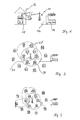
- FIG. 2 shows a data collector 24 which, in a first step, sends a broadcast call to all counters in its receiving area.
- the data collector 24 has a substantially circular reception area in which the counters 1, 2, 3, 4, 5 and 6 are located.
- the individual counters 1-6 set an acknowledgment of receipt on the received broadcast, with which the data collector 24 builds up the following route information: DATA COLLECTORS Active way: aim path RSSI Counter 1 data collector -30 dBm Counter 2 data collector -33 dBm Counter 3 data collector -27 dBm Counter 4 data collector -80 dBm Counter 5 data collector -110 dBm Counter 6 data collector -40 dBm
- counter 5 has a particularly bad radio connection to the data collector 24.
- a start signal is sent successively to the counter 1-6 from the data collector, which triggers the discontinuation of a broadcast at the respective transmitter.
- a start signal is sent to counter 6, whereupon this sends a broadcast, which is answered by the received counter with an acknowledgment.
- the circle 28 indicates the range of the counter 6.
- counters 1, 5, 7, 8 and the data collector 24 fall into the range of the counter 6.
- the counter 6 From the receipt confirmations, the counter 6 generates the following route information: Counter No. 6 Active way: aim path RSSI data collector Counter 6 -40 dBm Counter 1 Counter 6 -32 dBm Counter 5 Counter 6 -30 dBm Counter 7 Counter 6 -61 dBm Counter 8 Counter 6 -53 dBm
- the counter 5 has a good radio contact with counter 6 and is better received by this counter than the data collector 24.
- Such a deterioration can be done for example by a building or other shielding of the radio link.
- the counter 6 sends the route information to the data collector 24.
- the data collector evaluates the information of the individual counters 1-6 obtained in response to its start signal and generates a new route information therefrom. For the example above, the following route information then results: data collector Active way: aim path RSSI Counter 1 data collector -30 dBm Counter 2 data collector -33 dBm Counter 3 data collector -27 dBm Counter 4 data collector -80 dBm Counter 5 Counter 6 -30 dBm Counter 6 data collector -40 dBm Counter 7 Counter 6 -61 dBm Counter 8 Counter 6 -53 dBm
- Alternative ways Counter 5 I data collector -110 dBm
- counter number 6 is used here as a forwarding counter (repeater) in the network.
- Counters 5, 7, 8 are not addressed directly by the data collector, but signals and commands to these counters are addressed via the counter 6.
- automatically included in the generated network map is that for the counter 5, which was also accessible directly from the data collector, an alternative inactive way is stored.
- the alternative inactive path has a poorer transmission quality and is used if the active path does not work.
- the sum of the path information results in a network map, the routing control as Basis for addressing the data is used.
- Fig. 3 shows the expansion of the network after a start signal has been sent to counter 5.
- the counter 9 can be reached via the counter 5, so that the result is the following: Data collector ⁇ Payer 6 ⁇ Counter 5 ⁇ Counter 9.
- This path information is prefixed to the data packets to be sent in the radio network, so that each counter can analyze after receiving a data packet, whether to evaluate the contents of the data packet by its control or whether the data packet is to be forwarded.
- the data packet has the following structure: Position information payload checksum Path information is the path described above, where the unique identifier of the counters in the network is used.
- User data are preferably control commands or read counter readings. The checksum makes it possible to detect errors in the transmission of the data packet and to correct them for minor errors.
- the counters are uniquely assigned to a data collector.
- the data collector who has incorporated the counter in his network image, sends to this counter a LOCK TO COLLECTOR command which causes the counter to be fixed to the data collector is assigned.
- the counter confirms its assignment to the data collector.
- the ISM band at 868 MHz is preferably selected.
- the counter is dynamically integrated in a new, automatic network setup by the data collector.
- the renewed network construction can be started by a service only at the data collector.
- a data collector can be assigned to it by a command.
Landscapes
- Engineering & Computer Science (AREA)
- Computer Networks & Wireless Communication (AREA)
- Physics & Mathematics (AREA)
- General Physics & Mathematics (AREA)
- Mobile Radio Communication Systems (AREA)
- Arrangements For Transmission Of Measured Signals (AREA)
- Radio Relay Systems (AREA)
- Measurement Of Current Or Voltage (AREA)
- Circuits Of Receivers In General (AREA)
- Indexing, Searching, Synchronizing, And The Amount Of Synchronization Travel Of Record Carriers (AREA)
- Recording Measured Values (AREA)
Priority Applications (1)
| Application Number | Priority Date | Filing Date | Title |
|---|---|---|---|
| PL05077742T PL1672954T3 (pl) | 2004-12-20 | 2005-11-30 | Sposób i urządzenie do odczytywania stanów licznika |
Applications Claiming Priority (1)
| Application Number | Priority Date | Filing Date | Title |
|---|---|---|---|
| DE102004062157A DE102004062157B4 (de) | 2004-12-20 | 2004-12-20 | Vorrichtung zum Erfassen von Zählerständen |
Publications (3)
| Publication Number | Publication Date |
|---|---|
| EP1672954A2 true EP1672954A2 (fr) | 2006-06-21 |
| EP1672954A3 EP1672954A3 (fr) | 2008-03-19 |
| EP1672954B1 EP1672954B1 (fr) | 2010-07-28 |
Family
ID=36202444
Family Applications (1)
| Application Number | Title | Priority Date | Filing Date |
|---|---|---|---|
| EP05077742A Revoked EP1672954B1 (fr) | 2004-12-20 | 2005-11-30 | Dispositif et procédé destiné à la saisie d'affichages de compteurs |
Country Status (4)
| Country | Link |
|---|---|
| EP (1) | EP1672954B1 (fr) |
| AT (1) | ATE476061T1 (fr) |
| DE (2) | DE102004062157B4 (fr) |
| PL (1) | PL1672954T3 (fr) |
Families Citing this family (4)
| Publication number | Priority date | Publication date | Assignee | Title |
|---|---|---|---|---|
| DE102006045024A1 (de) * | 2006-09-23 | 2008-03-27 | Pfeiffer Vacuum Gmbh | Anordnung mit Vakuumgerät |
| DE102008044915A1 (de) | 2008-08-29 | 2010-03-04 | Lübeck, Felix | Verfahren zur automatischen Phasenerkennung mit fernausgelesenen Elektrizitätszählern |
| DE102008044909A1 (de) | 2008-08-31 | 2010-03-04 | Lübeck, Felix | Verfahren zur Erkennung von Notfällen mittels fernausgelesener Zähler |
| DE102015105873A1 (de) * | 2015-04-17 | 2016-10-20 | Sensus Spectrum Llc | Vorrichtung und Verfahren zur Übertragung von Verbrauchsdaten eines Verbraucherzählers in einem Funkkommunikationssystem |
Citations (4)
| Publication number | Priority date | Publication date | Assignee | Title |
|---|---|---|---|---|
| WO2001087279A2 (fr) | 2000-05-15 | 2001-11-22 | Smartsynch Ltd. | Architecture de reseau auto-organisatrice |
| DE19741085C2 (de) | 1997-09-18 | 2002-03-21 | Kundo Systemtechnik Gmbh | Verfahren zum zentralen Erfassen von an örtlich verteilten Datenstellen anliegenden Verbrauchsdaten in Gebäuden, insbesondere für Heizung und Warmwasser |
| DE10059868A1 (de) | 2000-11-30 | 2002-06-27 | Horst Ziegler | Verfahren zur Übertragung von Daten |
| EP1263167A1 (fr) | 2001-06-01 | 2002-12-04 | Zensys A/S | Sytème et procédé de construction de tables de routage et de routage de signaux dans un système d'automation |
Family Cites Families (1)
| Publication number | Priority date | Publication date | Assignee | Title |
|---|---|---|---|---|
| US20050055432A1 (en) * | 2003-09-08 | 2005-03-10 | Smart Synch, Inc. | Systems and methods for remote power management using 802.11 wireless protocols |
-
2004
- 2004-12-20 DE DE102004062157A patent/DE102004062157B4/de not_active Expired - Fee Related
-
2005
- 2005-11-30 DE DE502005010001T patent/DE502005010001D1/de not_active Withdrawn - After Issue
- 2005-11-30 AT AT05077742T patent/ATE476061T1/de active
- 2005-11-30 EP EP05077742A patent/EP1672954B1/fr not_active Revoked
- 2005-11-30 PL PL05077742T patent/PL1672954T3/pl unknown
Patent Citations (4)
| Publication number | Priority date | Publication date | Assignee | Title |
|---|---|---|---|---|
| DE19741085C2 (de) | 1997-09-18 | 2002-03-21 | Kundo Systemtechnik Gmbh | Verfahren zum zentralen Erfassen von an örtlich verteilten Datenstellen anliegenden Verbrauchsdaten in Gebäuden, insbesondere für Heizung und Warmwasser |
| WO2001087279A2 (fr) | 2000-05-15 | 2001-11-22 | Smartsynch Ltd. | Architecture de reseau auto-organisatrice |
| DE10059868A1 (de) | 2000-11-30 | 2002-06-27 | Horst Ziegler | Verfahren zur Übertragung von Daten |
| EP1263167A1 (fr) | 2001-06-01 | 2002-12-04 | Zensys A/S | Sytème et procédé de construction de tables de routage et de routage de signaux dans un système d'automation |
Also Published As
| Publication number | Publication date |
|---|---|
| DE502005010001D1 (de) | 2010-09-09 |
| EP1672954B1 (fr) | 2010-07-28 |
| EP1672954A3 (fr) | 2008-03-19 |
| DE102004062157A1 (de) | 2006-07-13 |
| DE102004062157B4 (de) | 2007-12-20 |
| PL1672954T3 (pl) | 2011-03-31 |
| ATE476061T1 (de) | 2010-08-15 |
Similar Documents
| Publication | Publication Date | Title |
|---|---|---|
| DE69900275T2 (de) | Weiterreichsteuerung in einem CDMA Zellularsystem | |
| DE60224212T2 (de) | Netzwerk mit mehreren sub-netzwerken | |
| EP1759537B1 (fr) | Procede d'etablissement d'un reseau de communication auto-organise sans fil et transfert de fonctionnalite de station de base | |
| DE102021103225A1 (de) | LoRaWAN-Gateway-Netzwerk und Verfahren | |
| DE60130905T2 (de) | Anordnung in einem verteilten steuersystem zur vergrösserung der verfügbarkeit von daten und/oder steuerbefehlen | |
| EP1672954B1 (fr) | Dispositif et procédé destiné à la saisie d'affichages de compteurs | |
| EP3477961B1 (fr) | Procédé de transfert des données et collecteur de données | |
| WO2008034676A1 (fr) | Procédé de radiotransmission dans un système avertisseur de danger | |
| EP1678877B1 (fr) | Procede pour transmettre des informations dans un systeme de communication a l'aide d'un chemin | |
| DE102011075957B4 (de) | Verfahren und System zur drahtlosen Datenübertragung | |
| EP1494191B1 (fr) | Procédé de la demande d'un utilisateur au système d'alarme radio | |
| DE102013110473B4 (de) | Verfahren zur parallelen Inbetriebnahme von Netzknoten eines Funknetzwerks | |
| DE10354943B4 (de) | Verfahren zum Betrieb einer Kommunikationsstrecke zwischen zumindest zwei Kommunikatonsendgeräten | |
| DE10045810C2 (de) | Datenübertragungseinrichtung für einen Wagenverbund | |
| DE10054931B4 (de) | Drahtlose Relaisstation für mehrere Funkschnittstellenstandards | |
| EP1172275B1 (fr) | Dispositif de transmission de données pour une composition de véhicules | |
| DE10031539C2 (de) | Verfahren und Anordnung zur Steuerung einer Sende-/Empfangseinrichtung durch Auswertung durchgeleiteter Signalisierung | |
| EP2560345A1 (fr) | Procédé et agencement de dispositif destinés à la transmission de données de consommation d'appareils de détection de données agencés de manière décentralisée | |
| WO2016166127A1 (fr) | Dispositif et procédé de transmission de données de consommation d'un compteur de consommation dans un système de radiocommunication | |
| WO2021130095A1 (fr) | Procédé de transmission de données à l'intérieur d'un système de transport ferroviaire, système de transmission de données, système de transport ferroviaire comprenant un système de transmission de données et utilisation d'unités de communication sur des éléments de champ | |
| DE102018131560A1 (de) | Selbstorganisiertes Datensammlernetzwerk | |
| WO2021009108A1 (fr) | Véhicule automobile comprenant un dispositif de communication, ainsi que procédé de transmission d'un paquet de données | |
| DE102010006340B4 (de) | System und Verfahren zur Datenübermittlung | |
| EP2119118A1 (fr) | Réseau de radiocommunication et procédé pour transférer des données dans un réseau de radiocommunication | |
| EP1282095A2 (fr) | Procédé de communication radio dans un système d'alarme |
Legal Events
| Date | Code | Title | Description |
|---|---|---|---|
| PUAI | Public reference made under article 153(3) epc to a published international application that has entered the european phase |
Free format text: ORIGINAL CODE: 0009012 |
|
| AK | Designated contracting states |
Kind code of ref document: A2 Designated state(s): AT BE BG CH CY CZ DE DK EE ES FI FR GB GR HU IE IS IT LI LT LU LV MC NL PL PT RO SE SI SK TR |
|
| AX | Request for extension of the european patent |
Extension state: AL BA HR MK YU |
|
| PUAL | Search report despatched |
Free format text: ORIGINAL CODE: 0009013 |
|
| AK | Designated contracting states |
Kind code of ref document: A3 Designated state(s): AT BE BG CH CY CZ DE DK EE ES FI FR GB GR HU IE IS IT LI LT LU LV MC NL PL PT RO SE SI SK TR |
|
| AX | Request for extension of the european patent |
Extension state: AL BA HR MK YU |
|
| RIC1 | Information provided on ipc code assigned before grant |
Ipc: G08C 17/02 20060101ALI20080214BHEP Ipc: H04Q 9/00 20060101AFI20060502BHEP Ipc: G01D 4/00 20060101ALI20080214BHEP |
|
| 17P | Request for examination filed |
Effective date: 20080913 |
|
| 17Q | First examination report despatched |
Effective date: 20081009 |
|
| AKX | Designation fees paid |
Designated state(s): AT BE BG CH CY CZ DE DK EE ES FI FR GB GR HU IE IS IT LI LT LU LV MC NL PL PT RO SE SI SK TR |
|
| GRAP | Despatch of communication of intention to grant a patent |
Free format text: ORIGINAL CODE: EPIDOSNIGR1 |
|
| GRAS | Grant fee paid |
Free format text: ORIGINAL CODE: EPIDOSNIGR3 |
|
| GRAA | (expected) grant |
Free format text: ORIGINAL CODE: 0009210 |
|
| AK | Designated contracting states |
Kind code of ref document: B1 Designated state(s): AT BE BG CH CY CZ DE DK EE ES FI FR GB GR HU IE IS IT LI LT LU LV MC NL PL PT RO SE SI SK TR |
|
| REG | Reference to a national code |
Ref country code: GB Ref legal event code: FG4D Free format text: NOT ENGLISH |
|
| REG | Reference to a national code |
Ref country code: CH Ref legal event code: EP |
|
| REG | Reference to a national code |
Ref country code: IE Ref legal event code: FG4D Free format text: LANGUAGE OF EP DOCUMENT: GERMAN |
|
| REF | Corresponds to: |
Ref document number: 502005010001 Country of ref document: DE Date of ref document: 20100909 Kind code of ref document: P |
|
| REG | Reference to a national code |
Ref country code: CH Ref legal event code: NV Representative=s name: BOHEST AG |
|
| RAP2 | Party data changed (patent owner data changed or rights of a patent transferred) |
Owner name: EMH METERING GMBH & CO. KG |
|
| REG | Reference to a national code |
Ref country code: NL Ref legal event code: VDEP Effective date: 20100728 |
|
| PG25 | Lapsed in a contracting state [announced via postgrant information from national office to epo] |
Ref country code: DE Free format text: LAPSE BECAUSE OF THE APPLICANT RENOUNCES Effective date: 20100819 |
|
| PG25 | Lapsed in a contracting state [announced via postgrant information from national office to epo] |
Ref country code: NL Free format text: LAPSE BECAUSE OF FAILURE TO SUBMIT A TRANSLATION OF THE DESCRIPTION OR TO PAY THE FEE WITHIN THE PRESCRIBED TIME-LIMIT Effective date: 20100728 Ref country code: FI Free format text: LAPSE BECAUSE OF FAILURE TO SUBMIT A TRANSLATION OF THE DESCRIPTION OR TO PAY THE FEE WITHIN THE PRESCRIBED TIME-LIMIT Effective date: 20100728 |
|
| PGFP | Annual fee paid to national office [announced via postgrant information from national office to epo] |
Ref country code: AT Payment date: 20101119 Year of fee payment: 6 |
|
| REG | Reference to a national code |
Ref country code: SK Ref legal event code: T3 Ref document number: E 8170 Country of ref document: SK |
|
| PG25 | Lapsed in a contracting state [announced via postgrant information from national office to epo] |
Ref country code: BG Free format text: LAPSE BECAUSE OF FAILURE TO SUBMIT A TRANSLATION OF THE DESCRIPTION OR TO PAY THE FEE WITHIN THE PRESCRIBED TIME-LIMIT Effective date: 20101028 Ref country code: CY Free format text: LAPSE BECAUSE OF FAILURE TO SUBMIT A TRANSLATION OF THE DESCRIPTION OR TO PAY THE FEE WITHIN THE PRESCRIBED TIME-LIMIT Effective date: 20100728 Ref country code: SI Free format text: LAPSE BECAUSE OF FAILURE TO SUBMIT A TRANSLATION OF THE DESCRIPTION OR TO PAY THE FEE WITHIN THE PRESCRIBED TIME-LIMIT Effective date: 20100728 Ref country code: IS Free format text: LAPSE BECAUSE OF FAILURE TO SUBMIT A TRANSLATION OF THE DESCRIPTION OR TO PAY THE FEE WITHIN THE PRESCRIBED TIME-LIMIT Effective date: 20101128 Ref country code: PT Free format text: LAPSE BECAUSE OF FAILURE TO SUBMIT A TRANSLATION OF THE DESCRIPTION OR TO PAY THE FEE WITHIN THE PRESCRIBED TIME-LIMIT Effective date: 20101129 |
|
| PGFP | Annual fee paid to national office [announced via postgrant information from national office to epo] |
Ref country code: SK Payment date: 20101116 Year of fee payment: 6 |
|
| REG | Reference to a national code |
Ref country code: IE Ref legal event code: FD4D |
|
| PG25 | Lapsed in a contracting state [announced via postgrant information from national office to epo] |
Ref country code: SE Free format text: LAPSE BECAUSE OF FAILURE TO SUBMIT A TRANSLATION OF THE DESCRIPTION OR TO PAY THE FEE WITHIN THE PRESCRIBED TIME-LIMIT Effective date: 20100728 Ref country code: LV Free format text: LAPSE BECAUSE OF FAILURE TO SUBMIT A TRANSLATION OF THE DESCRIPTION OR TO PAY THE FEE WITHIN THE PRESCRIBED TIME-LIMIT Effective date: 20100728 Ref country code: GR Free format text: LAPSE BECAUSE OF FAILURE TO SUBMIT A TRANSLATION OF THE DESCRIPTION OR TO PAY THE FEE WITHIN THE PRESCRIBED TIME-LIMIT Effective date: 20101029 |
|
| REG | Reference to a national code |
Ref country code: PL Ref legal event code: T3 |
|
| PG25 | Lapsed in a contracting state [announced via postgrant information from national office to epo] |
Ref country code: DK Free format text: LAPSE BECAUSE OF FAILURE TO SUBMIT A TRANSLATION OF THE DESCRIPTION OR TO PAY THE FEE WITHIN THE PRESCRIBED TIME-LIMIT Effective date: 20100728 Ref country code: IE Free format text: LAPSE BECAUSE OF FAILURE TO SUBMIT A TRANSLATION OF THE DESCRIPTION OR TO PAY THE FEE WITHIN THE PRESCRIBED TIME-LIMIT Effective date: 20100728 |
|
| PLBI | Opposition filed |
Free format text: ORIGINAL CODE: 0009260 |
|
| PLAX | Notice of opposition and request to file observation + time limit sent |
Free format text: ORIGINAL CODE: EPIDOSNOBS2 |
|
| BERE | Be: lapsed |
Owner name: EMH ELEKTRIZITATSZAHLER G.M.B.H. & CO KG Effective date: 20101130 |
|
| PG25 | Lapsed in a contracting state [announced via postgrant information from national office to epo] |
Ref country code: RO Free format text: LAPSE BECAUSE OF FAILURE TO SUBMIT A TRANSLATION OF THE DESCRIPTION OR TO PAY THE FEE WITHIN THE PRESCRIBED TIME-LIMIT Effective date: 20100728 Ref country code: EE Free format text: LAPSE BECAUSE OF FAILURE TO SUBMIT A TRANSLATION OF THE DESCRIPTION OR TO PAY THE FEE WITHIN THE PRESCRIBED TIME-LIMIT Effective date: 20100728 Ref country code: CZ Free format text: LAPSE BECAUSE OF FAILURE TO SUBMIT A TRANSLATION OF THE DESCRIPTION OR TO PAY THE FEE WITHIN THE PRESCRIBED TIME-LIMIT Effective date: 20100728 |
|
| 26 | Opposition filed |
Opponent name: PAJARO LIMITED Effective date: 20110428 |
|
| PG25 | Lapsed in a contracting state [announced via postgrant information from national office to epo] |
Ref country code: ES Free format text: LAPSE BECAUSE OF FAILURE TO SUBMIT A TRANSLATION OF THE DESCRIPTION OR TO PAY THE FEE WITHIN THE PRESCRIBED TIME-LIMIT Effective date: 20101108 Ref country code: MC Free format text: LAPSE BECAUSE OF NON-PAYMENT OF DUE FEES Effective date: 20101130 |
|
| GBPC | Gb: european patent ceased through non-payment of renewal fee |
Effective date: 20101130 |
|
| PG25 | Lapsed in a contracting state [announced via postgrant information from national office to epo] |
Ref country code: BE Free format text: LAPSE BECAUSE OF NON-PAYMENT OF DUE FEES Effective date: 20101130 |
|
| REG | Reference to a national code |
Ref country code: DE Ref legal event code: R026 Ref document number: 502005010001 Country of ref document: DE Effective date: 20110428 |
|
| PLBB | Reply of patent proprietor to notice(s) of opposition received |
Free format text: ORIGINAL CODE: EPIDOSNOBS3 |
|
| PG25 | Lapsed in a contracting state [announced via postgrant information from national office to epo] |
Ref country code: GB Free format text: LAPSE BECAUSE OF NON-PAYMENT OF DUE FEES Effective date: 20101130 |
|
| PG25 | Lapsed in a contracting state [announced via postgrant information from national office to epo] |
Ref country code: HU Free format text: LAPSE BECAUSE OF FAILURE TO SUBMIT A TRANSLATION OF THE DESCRIPTION OR TO PAY THE FEE WITHIN THE PRESCRIBED TIME-LIMIT Effective date: 20110129 Ref country code: LU Free format text: LAPSE BECAUSE OF NON-PAYMENT OF DUE FEES Effective date: 20101130 |
|
| PG25 | Lapsed in a contracting state [announced via postgrant information from national office to epo] |
Ref country code: TR Free format text: LAPSE BECAUSE OF FAILURE TO SUBMIT A TRANSLATION OF THE DESCRIPTION OR TO PAY THE FEE WITHIN THE PRESCRIBED TIME-LIMIT Effective date: 20100728 |
|
| APBM | Appeal reference recorded |
Free format text: ORIGINAL CODE: EPIDOSNREFNO |
|
| APBP | Date of receipt of notice of appeal recorded |
Free format text: ORIGINAL CODE: EPIDOSNNOA2O |
|
| APAH | Appeal reference modified |
Free format text: ORIGINAL CODE: EPIDOSCREFNO |
|
| APBM | Appeal reference recorded |
Free format text: ORIGINAL CODE: EPIDOSNREFNO |
|
| APBP | Date of receipt of notice of appeal recorded |
Free format text: ORIGINAL CODE: EPIDOSNNOA2O |
|
| APBQ | Date of receipt of statement of grounds of appeal recorded |
Free format text: ORIGINAL CODE: EPIDOSNNOA3O |
|
| APBQ | Date of receipt of statement of grounds of appeal recorded |
Free format text: ORIGINAL CODE: EPIDOSNNOA3O |
|
| REG | Reference to a national code |
Ref country code: AT Ref legal event code: MM01 Ref document number: 476061 Country of ref document: AT Kind code of ref document: T Effective date: 20121130 |
|
| PG25 | Lapsed in a contracting state [announced via postgrant information from national office to epo] |
Ref country code: AT Free format text: LAPSE BECAUSE OF NON-PAYMENT OF DUE FEES Effective date: 20121130 Ref country code: SK Free format text: LAPSE BECAUSE OF NON-PAYMENT OF DUE FEES Effective date: 20121130 |
|
| REG | Reference to a national code |
Ref country code: SK Ref legal event code: MM4A Ref document number: E 8170 Country of ref document: SK Effective date: 20121130 |
|
| PGFP | Annual fee paid to national office [announced via postgrant information from national office to epo] |
Ref country code: LT Payment date: 20131121 Year of fee payment: 9 |
|
| REG | Reference to a national code |
Ref country code: CH Ref legal event code: PCAR Free format text: NEW ADDRESS: HOLBEINSTRASSE 36-38, 4051 BASEL (CH) |
|
| PGFP | Annual fee paid to national office [announced via postgrant information from national office to epo] |
Ref country code: CH Payment date: 20141120 Year of fee payment: 10 |
|
| PGFP | Annual fee paid to national office [announced via postgrant information from national office to epo] |
Ref country code: PL Payment date: 20141118 Year of fee payment: 10 Ref country code: FR Payment date: 20141127 Year of fee payment: 10 |
|
| PGFP | Annual fee paid to national office [announced via postgrant information from national office to epo] |
Ref country code: IT Payment date: 20141127 Year of fee payment: 10 |
|
| PLAB | Opposition data, opponent's data or that of the opponent's representative modified |
Free format text: ORIGINAL CODE: 0009299OPPO |
|
| R26 | Opposition filed (corrected) |
Opponent name: PAJARO LIMITED Effective date: 20110428 |
|
| REG | Reference to a national code |
Ref country code: LT Ref legal event code: MM4D Effective date: 20141130 |
|
| PG25 | Lapsed in a contracting state [announced via postgrant information from national office to epo] |
Ref country code: LT Free format text: LAPSE BECAUSE OF NON-PAYMENT OF DUE FEES Effective date: 20141130 |
|
| APBU | Appeal procedure closed |
Free format text: ORIGINAL CODE: EPIDOSNNOA9O |
|
| REG | Reference to a national code |
Ref country code: CH Ref legal event code: PL |
|
| PG25 | Lapsed in a contracting state [announced via postgrant information from national office to epo] |
Ref country code: CH Free format text: LAPSE BECAUSE OF NON-PAYMENT OF DUE FEES Effective date: 20151130 Ref country code: IT Free format text: LAPSE BECAUSE OF NON-PAYMENT OF DUE FEES Effective date: 20151130 Ref country code: LI Free format text: LAPSE BECAUSE OF NON-PAYMENT OF DUE FEES Effective date: 20151130 |
|
| REG | Reference to a national code |
Ref country code: FR Ref legal event code: ST Effective date: 20160729 |
|
| PG25 | Lapsed in a contracting state [announced via postgrant information from national office to epo] |
Ref country code: FR Free format text: LAPSE BECAUSE OF NON-PAYMENT OF DUE FEES Effective date: 20151130 |
|
| RDAF | Communication despatched that patent is revoked |
Free format text: ORIGINAL CODE: EPIDOSNREV1 |
|
| STAA | Information on the status of an ep patent application or granted ep patent |
Free format text: STATUS: THE PATENT HAS BEEN GRANTED |
|
| REG | Reference to a national code |
Ref country code: DE Ref legal event code: R064 Ref document number: 502005010001 Country of ref document: DE Ref country code: DE Ref legal event code: R103 Ref document number: 502005010001 Country of ref document: DE |
|
| PG25 | Lapsed in a contracting state [announced via postgrant information from national office to epo] |
Ref country code: PL Free format text: LAPSE BECAUSE OF NON-PAYMENT OF DUE FEES Effective date: 20151130 |
|
| RDAG | Patent revoked |
Free format text: ORIGINAL CODE: 0009271 |
|
| STAA | Information on the status of an ep patent application or granted ep patent |
Free format text: STATUS: PATENT REVOKED |
|
| PLAB | Opposition data, opponent's data or that of the opponent's representative modified |
Free format text: ORIGINAL CODE: 0009299OPPO |
|
| 27W | Patent revoked |
Effective date: 20170202 |
|
| R26 | Opposition filed (corrected) |
Opponent name: PAJARO LIMITED Effective date: 20110428 |
|
| REG | Reference to a national code |
Ref country code: AT Ref legal event code: MA03 Ref document number: 476061 Country of ref document: AT Kind code of ref document: T Effective date: 20170202 |
|
| STAA | Information on the status of an ep patent application or granted ep patent |
Free format text: STATUS: PATENT REVOKED |