EP1672954A2 - Device and method for recording meter readings - Google Patents
Device and method for recording meter readings Download PDFInfo
- Publication number
- EP1672954A2 EP1672954A2 EP05077742A EP05077742A EP1672954A2 EP 1672954 A2 EP1672954 A2 EP 1672954A2 EP 05077742 A EP05077742 A EP 05077742A EP 05077742 A EP05077742 A EP 05077742A EP 1672954 A2 EP1672954 A2 EP 1672954A2
- Authority
- EP
- European Patent Office
- Prior art keywords
- data
- counter
- data collector
- received
- radio
- Prior art date
- Legal status (The legal status is an assumption and is not a legal conclusion. Google has not performed a legal analysis and makes no representation as to the accuracy of the status listed.)
- Granted
Links
Images
Classifications
-
- G—PHYSICS
- G01—MEASURING; TESTING
- G01D—MEASURING NOT SPECIALLY ADAPTED FOR A SPECIFIC VARIABLE; ARRANGEMENTS FOR MEASURING TWO OR MORE VARIABLES NOT COVERED IN A SINGLE OTHER SUBCLASS; TARIFF METERING APPARATUS; MEASURING OR TESTING NOT OTHERWISE PROVIDED FOR
- G01D4/00—Tariff metering apparatus
- G01D4/002—Remote reading of utility meters
- G01D4/004—Remote reading of utility meters to a fixed location
-
- H—ELECTRICITY
- H04—ELECTRIC COMMUNICATION TECHNIQUE
- H04Q—SELECTING
- H04Q9/00—Arrangements in telecontrol or telemetry systems for selectively calling a substation from a main station, in which substation desired apparatus is selected for applying a control signal thereto or for obtaining measured values therefrom
-
- G—PHYSICS
- G01—MEASURING; TESTING
- G01D—MEASURING NOT SPECIALLY ADAPTED FOR A SPECIFIC VARIABLE; ARRANGEMENTS FOR MEASURING TWO OR MORE VARIABLES NOT COVERED IN A SINGLE OTHER SUBCLASS; TARIFF METERING APPARATUS; MEASURING OR TESTING NOT OTHERWISE PROVIDED FOR
- G01D2204/00—Indexing scheme relating to details of tariff-metering apparatus
- G01D2204/40—Networks; Topology
- G01D2204/45—Utility meters networked together within a single building
-
- H—ELECTRICITY
- H04—ELECTRIC COMMUNICATION TECHNIQUE
- H04Q—SELECTING
- H04Q2209/00—Arrangements in telecontrol or telemetry systems
- H04Q2209/40—Arrangements in telecontrol or telemetry systems using a wireless architecture
-
- H—ELECTRICITY
- H04—ELECTRIC COMMUNICATION TECHNIQUE
- H04Q—SELECTING
- H04Q2209/00—Arrangements in telecontrol or telemetry systems
- H04Q2209/50—Arrangements in telecontrol or telemetry systems using a mobile data collecting device, e.g. walk by or drive by
-
- H—ELECTRICITY
- H04—ELECTRIC COMMUNICATION TECHNIQUE
- H04Q—SELECTING
- H04Q2209/00—Arrangements in telecontrol or telemetry systems
- H04Q2209/60—Arrangements in telecontrol or telemetry systems for transmitting utility meters data, i.e. transmission of data from the reader of the utility meter
-
- Y—GENERAL TAGGING OF NEW TECHNOLOGICAL DEVELOPMENTS; GENERAL TAGGING OF CROSS-SECTIONAL TECHNOLOGIES SPANNING OVER SEVERAL SECTIONS OF THE IPC; TECHNICAL SUBJECTS COVERED BY FORMER USPC CROSS-REFERENCE ART COLLECTIONS [XRACs] AND DIGESTS
- Y02—TECHNOLOGIES OR APPLICATIONS FOR MITIGATION OR ADAPTATION AGAINST CLIMATE CHANGE
- Y02B—CLIMATE CHANGE MITIGATION TECHNOLOGIES RELATED TO BUILDINGS, e.g. HOUSING, HOUSE APPLIANCES OR RELATED END-USER APPLICATIONS
- Y02B90/00—Enabling technologies or technologies with a potential or indirect contribution to GHG emissions mitigation
- Y02B90/20—Smart grids as enabling technology in buildings sector
-
- Y—GENERAL TAGGING OF NEW TECHNOLOGICAL DEVELOPMENTS; GENERAL TAGGING OF CROSS-SECTIONAL TECHNOLOGIES SPANNING OVER SEVERAL SECTIONS OF THE IPC; TECHNICAL SUBJECTS COVERED BY FORMER USPC CROSS-REFERENCE ART COLLECTIONS [XRACs] AND DIGESTS
- Y04—INFORMATION OR COMMUNICATION TECHNOLOGIES HAVING AN IMPACT ON OTHER TECHNOLOGY AREAS
- Y04S—SYSTEMS INTEGRATING TECHNOLOGIES RELATED TO POWER NETWORK OPERATION, COMMUNICATION OR INFORMATION TECHNOLOGIES FOR IMPROVING THE ELECTRICAL POWER GENERATION, TRANSMISSION, DISTRIBUTION, MANAGEMENT OR USAGE, i.e. SMART GRIDS
- Y04S20/00—Management or operation of end-user stationary applications or the last stages of power distribution; Controlling, monitoring or operating thereof
- Y04S20/30—Smart metering, e.g. specially adapted for remote reading
Definitions
- the present invention relates to an apparatus and a method for detecting counter readings and for communicating and exchanging data with counters.
- Below meters are understood electricity meters, water, heat and gas meters, but also other counters. So far, counters, especially counters in households are mainly read manually, which is time consuming and costly. Also, in a manual reading can not always be read at a predetermined time, but the reading times can vary widely.
- a method for the transmission of data is known.
- the radio units of terminals for example energy consumption meters
- central radio units which are allocated, for example, in each case to a residential unit and to the associated terminals.
- a second central radio unit associated with another residential unit may be included. This then occurs in immediate Connects to the terminal and forwards the data to the first central radio unit.
- each counter has a unique identifier and is connected to a radio unit.
- a central data collector which can exchange data with the radio units of the meter directly and indirectly via other radio units.
- the query of the data of a particular counter takes place in this known method, starting from the data collector according to the "snowball principle", d. h., The request is first addressed to all directly reachable radio units and then forwarded in a chain of these to all of these radio units reachable from further radio units until the radio unit of the queried counter is reached.
- the object of the invention is to provide a device and a method for detecting counter readings which, by simple means, offer the possibility of reading off a multiplicity of counters and exchanging them with these data in an efficient manner.
- the inventive device for detecting counter readings and for communication and exchange of data is provided for at least one counter, which has a unique identifier and is connected to a radio unit.
- the radio unit is provided to transmit and receive radio signals. It works preferably in a so-called ISM band at 868 MHz.
- the device additionally comprises at least one data collector, which also has a radio unit which receives the meter reading and data from at least one counter and transmits data over a radio link, and has a controller which forwards the received meter reading.
- the data collector receives the counter reading (s) as well as other data from the at least one counter and forwards the counter readings thus received, for example to the superordinate data collector.
- the data collector also exchanges general data with the meter.
- the data collector has a routing control.
- the routing controller includes route information having at least one way for each counter in the radio network to send data from the data collector to the counter and receive data from the counter.
- the path information provides either a direct transmission to the receiver or an indirect transmission via one or more counters which forward the transmitted data along the specified path.
- the device of the invention operates with a data collector in which also receive data that has been forwarded through a variety of other, listed in the path information for the connection counters. In the According to the invention, it is no longer necessary to be with the data collector in the often short-range receiving radius of a counter with radio transmitter.
- the device according to the invention it is rather possible to work with a stationary data collector, to which data are relayed via path information from the counters. Particularly advantageous here is that no complex control is required for the radio units of the counter, but a simple micro-controller can forward the data.
- the routing control ensures that the data is only forwarded along the path specified by the routing control in order to communicate the data collector with a specific counter. Consequently, only those counters involved in the data communication included in this path are involved. The required data traffic can be reduced. In addition, multiple communications can be performed at the same time.
- the device according to the invention considerably reduces the expenditure for reading meters.
- each radio unit both the data collector and the counter has a control to send on a received broadcast an acknowledgment with an identifier.
- a defined signal sequence which is referred to as a broadcast, can be issued by the radio unit of the counter or of the data collector and triggers the receivers of the broadcast to issue a counter signal out.
- the counter signal is an acknowledgment of receipt that confirms the sender of the broadcast the receipt of the signal and preferably also sends information about the quality.
- the quality of the radio link can also be assessed by the recipient of the acknowledgment.
- the acknowledgments give the broadcaster of a broadcast an image of existing receivers in its environment and preferably also on the quality of the radio link, such as the received field strength of the signals and / or their bit error rate.
- each of the radio units has a controller which responds to a start signal initiated by the data collector, initiates a broadcast and returns the received data of the broadcast to the data collector.
- a data collector can build a network map that extends beyond the range of the radio unit of the data collector.
- start and broadcast signal controls allows signals to be sent from the meters over long distances to the data collector, even under the most difficult radio conditions.
- one or more radio units for forwarding the data can be provided to support the network at the predetermined location.
- the object of the invention is also achieved by a method having the features of claim 6.
- the inventive method is used for detecting and exchanging data counter readings in at least one counter, which has a unique identifier and is connected to a radio unit.
- the method comprises the step of a data collector with a radio unit exchanging data with at least one counter via a radio network and / or forwarding to it.
- the data collector has a network mapping routing controller in which each counter is assigned a path through which the data collector sends data to the counter.
- the path consists of either direct transmission to the counter or indirect transmission via other counters that forward the transmitted data along a specified path.
- the inventively provided routing control for mapping the network allows the data collector to also evaluate data from counters that can not send directly to the data collector.
- the data collector's routing control assigns each counter a path through which data is sent to the meter.
- the counters have no controller that selects a path to the data collector for data.
- path information is communicated with the data from the data collector to the counters and used by the controller for sending data back to the data collector.
- the counters assigned to the nodes of the route function as intermediate stations over which the data are forwarded.
- the data in a section contain information about the path predetermined by the routing control along which the data is to be forwarded.
- this information may be in the form of a list that includes, in order, the identifiers of all counters along the way.
- the first entry in this list identifies the counter responsible for the upcoming forwarding step.
- This counter can reorder the list in the header before forwarding so that the identifier of the next counter is first in the list.
- the identifier of the reordering meter itself is placed at the end of the list. In this way, the route-specifying list is maintained in the correct order and, if appropriate, can also be used for the "return" of the data.
- each radio unit has a controller to send on a received broadcast an acknowledgment with an identifier of the associated counter which has received the broadcast.
- the acknowledgment also contains information on the strength and quality of the received broadcast signal.
- each controller of the radio has the ability to send a request for broadcast.
- the controller of the radio unit of the data collector responds to the request of the data collector, the controller of the radio unit of the data collector generates a broadcast signal and receives back the received acknowledgments received on the broadcast signal.
- the meters reached in this way can be reached via the path length 1.
- a second step which takes place on the basis of the received acknowledgments of the returned radio units from the first step, these successively with a request from Data collector addressed.
- these radio units broadcast a broadcast.
- the data collector receives the collected and forwarded acknowledgments of receipt of all radio units which can be reached via a path of length 2 or less.
- the radio units can now be addressed with a distance of length 2, ie with an intermediate station, with a start signal in order to generate from the feedback a list of the radio units with the length 3.
- the special feature of the network that builds up in this way is that counters which are outside the range of the data collector and can not be directly accessed by the data collector can be reached by forwarding the data via neighboring counters.
- each meter has exactly one data collector. The counter can thus detect whether it is responsible for forwarded signals.
- FIG. 1 shows a schematic view of a stationary data collector 10 which is connected to a billing company 14 via a data line 12.
- the consumer 16 - shown here as a home - is equipped with an electricity meter 18.
- the electricity meter 18 has a unique identifier 20 and a radio transceiver 22.
- the identifier 20 may either be an identifier assigned directly to the counter 18 or an indirect identifier that is self-determining via an identifier of the radio transceiver 22.
- the radio transceiver 22 is designed as a module to be integrated into the counter. It is also possible to connect the radio transceiver as a module via cable or the like with its counter.
- the transceiver 22 is designed in the example illustrated in FIG. 1 to receive direct radio contact with the data collector 10.
- the structure shown schematically in Fig. 1 forms a network with a counter 18 whose meter readings can be read via radio and communicated with the.
- the counter 1 provided in FIG. 1 by the reference numeral 18, is in direct communication with the data collector 10.
- the reception field strength in the example is 30 dBm.
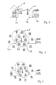
- FIG. 2 shows a data collector 24 which, in a first step, sends a broadcast call to all counters in its receiving area.
- the data collector 24 has a substantially circular reception area in which the counters 1, 2, 3, 4, 5 and 6 are located.
- the individual counters 1-6 set an acknowledgment of receipt on the received broadcast, with which the data collector 24 builds up the following route information: DATA COLLECTORS Active way: aim path RSSI Counter 1 data collector -30 dBm Counter 2 data collector -33 dBm Counter 3 data collector -27 dBm Counter 4 data collector -80 dBm Counter 5 data collector -110 dBm Counter 6 data collector -40 dBm
- counter 5 has a particularly bad radio connection to the data collector 24.
- a start signal is sent successively to the counter 1-6 from the data collector, which triggers the discontinuation of a broadcast at the respective transmitter.
- a start signal is sent to counter 6, whereupon this sends a broadcast, which is answered by the received counter with an acknowledgment.
- the circle 28 indicates the range of the counter 6.
- counters 1, 5, 7, 8 and the data collector 24 fall into the range of the counter 6.
- the counter 6 From the receipt confirmations, the counter 6 generates the following route information: Counter No. 6 Active way: aim path RSSI data collector Counter 6 -40 dBm Counter 1 Counter 6 -32 dBm Counter 5 Counter 6 -30 dBm Counter 7 Counter 6 -61 dBm Counter 8 Counter 6 -53 dBm
- the counter 5 has a good radio contact with counter 6 and is better received by this counter than the data collector 24.
- Such a deterioration can be done for example by a building or other shielding of the radio link.
- the counter 6 sends the route information to the data collector 24.
- the data collector evaluates the information of the individual counters 1-6 obtained in response to its start signal and generates a new route information therefrom. For the example above, the following route information then results: data collector Active way: aim path RSSI Counter 1 data collector -30 dBm Counter 2 data collector -33 dBm Counter 3 data collector -27 dBm Counter 4 data collector -80 dBm Counter 5 Counter 6 -30 dBm Counter 6 data collector -40 dBm Counter 7 Counter 6 -61 dBm Counter 8 Counter 6 -53 dBm
- Alternative ways Counter 5 I data collector -110 dBm
- counter number 6 is used here as a forwarding counter (repeater) in the network.
- Counters 5, 7, 8 are not addressed directly by the data collector, but signals and commands to these counters are addressed via the counter 6.
- automatically included in the generated network map is that for the counter 5, which was also accessible directly from the data collector, an alternative inactive way is stored.
- the alternative inactive path has a poorer transmission quality and is used if the active path does not work.
- the sum of the path information results in a network map, the routing control as Basis for addressing the data is used.
- Fig. 3 shows the expansion of the network after a start signal has been sent to counter 5.
- the counter 9 can be reached via the counter 5, so that the result is the following: Data collector ⁇ Payer 6 ⁇ Counter 5 ⁇ Counter 9.
- This path information is prefixed to the data packets to be sent in the radio network, so that each counter can analyze after receiving a data packet, whether to evaluate the contents of the data packet by its control or whether the data packet is to be forwarded.
- the data packet has the following structure: Position information payload checksum Path information is the path described above, where the unique identifier of the counters in the network is used.
- User data are preferably control commands or read counter readings. The checksum makes it possible to detect errors in the transmission of the data packet and to correct them for minor errors.
- the counters are uniquely assigned to a data collector.
- the data collector who has incorporated the counter in his network image, sends to this counter a LOCK TO COLLECTOR command which causes the counter to be fixed to the data collector is assigned.
- the counter confirms its assignment to the data collector.
- the ISM band at 868 MHz is preferably selected.
- the counter is dynamically integrated in a new, automatic network setup by the data collector.
- the renewed network construction can be started by a service only at the data collector.
- a data collector can be assigned to it by a command.
Abstract
Description
Die vorliegende Erfindung betrifft eine Vorrichtung und ein Verfahren zum Erfassen von Zählerständen und zur Kommunikation sowie zum Austausch von Daten mit Zählern. Unter Zählern werden nachfolgend Elektrizitätszähler, Wasser-, Wärme- und auch Gaszähler verstanden, aber auch andere Zähler. Bisher werden Zähler, insbesondere Zähler in Haushalten überwiegend manuell abgelesen, was zeit- und kostenintensiv ist. Auch kann bei einem manuellen Ablesen nicht immer zu einem vorbestimmten Zeitpunkt abgelesen werden, sondern die Ablesezeitpunkte können stark variieren.The present invention relates to an apparatus and a method for detecting counter readings and for communicating and exchanging data with counters. Below meters are understood electricity meters, water, heat and gas meters, but also other counters. So far, counters, especially counters in households are mainly read manually, which is time consuming and costly. Also, in a manual reading can not always be read at a predetermined time, but the reading times can vary widely.
Es ist bekannt, Zähler mit einer Funkeinheit auszustatten, um eine Zählerstandübermittlung über eine kurze Funkstrecke vorzunehmen. Hierbei befindet sich beispielsweise eine mit dem Ablesen beauftragte Person mit einem mobilen Datensammler in der Funkreichweite der Zähler, so daß ähnliche Nachteile wie bei der manuellen Ablesung auftreten. Bei diesem Vorgehen senden die Zähler automatisch an den mobilen Datensammler oder an einen Datenkonzentrator, beispielsweise für eine Heizkostenabrechnung.It is known to equip counters with a radio unit in order to carry out a meter reading transmission over a short radio link. In this case, for example, a person instructed to read is with a mobile data collector in the radio range of the counters, so that similar disadvantages occur as in the manual reading. In this procedure, the counters automatically send to the mobile data collector or to a data concentrator, for example for a heating billing.
Aus DE 100 59 868 A1 ist ein Verfahren zur Übertragung von Daten bekannt. Dabei kommunizieren die Funkeinheiten von Endgeräten, beispielsweise Energieverbrauchszählern, immer mit zentralen Funkeinheiten, welche beispielsweise jeweils einer Wohneinheit und den zugehörigen Endgeräten zugeordnet sind. Um eine Kommunikation mit einem Endgerät, das von der zugehörigen zentralen Funkeinheit aus nicht direkt erreichbar ist, zu ermöglichen, kann eine zweite, einer anderen Wohneinheit zugeordnete zentrale Funkeinheit einbezogen werden. Diese tritt dann in unmittelbare Verbindung mit dem Endgerät und leitet die Daten an die erste zentrale Funkeinheit weiter.From DE 100 59 868 A1 a method for the transmission of data is known. In this case, the radio units of terminals, for example energy consumption meters, always communicate with central radio units, which are allocated, for example, in each case to a residential unit and to the associated terminals. In order to enable communication with a terminal not directly accessible from the associated central radio unit, a second central radio unit associated with another residential unit may be included. This then occurs in immediate Connects to the terminal and forwards the data to the first central radio unit.
Ebenfalls bekannt ist ein Verfahren zum Erfassen von Zählerständen aus DE 197 41 085 C2. Bei diesem bekannten Verfahren besitzt jeder Zähler eine eindeutige Kennung und ist mit einer Funkeinheit verbunden. Außerdem gibt es einen zentralen Datensammler, der mit den Funkeinheiten der Zähler unmittelbar und auch mittelbar über weitere Funkeinheiten Daten austauschen kann. Die Abfrage der Daten eines bestimmten Zählers erfolgt bei diesem bekannten Verfahren ausgehend vom Datensammler nach dem "Schneeballprinzip", d. h., die Anfrage wird zunächst an alle unmittelbar erreichbaren Funkeinheiten gerichtet und dann in einer Kette von diesen solange an alle von diesen Funkeinheiten aus erreichbaren weiteren Funkeinheiten weitergeleitet, bis die Funkeinheit des abzufragenden Zählers erreicht ist.Also known is a method for detecting counter readings from DE 197 41 085 C2. In this known method, each counter has a unique identifier and is connected to a radio unit. In addition, there is a central data collector, which can exchange data with the radio units of the meter directly and indirectly via other radio units. The query of the data of a particular counter takes place in this known method, starting from the data collector according to the "snowball principle", d. h., The request is first addressed to all directly reachable radio units and then forwarded in a chain of these to all of these radio units reachable from further radio units until the radio unit of the queried counter is reached.
Davon ausgehend liegt der Erfindung die Aufgabe zugrunde, eine Vorrichtung und ein Verfahren zum Erfassen von Zählerständen bereitzustellen, die bzw. das mit einfachen Mitteln die Möglichkeit bieten, eine Vielzahl von Zählern abzulesen und mit diesen Daten in effizienter Weise auszutauschen.Based on this, the object of the invention is to provide a device and a method for detecting counter readings which, by simple means, offer the possibility of reading off a multiplicity of counters and exchanging them with these data in an efficient manner.
Die vorstehende Aufgabe wird durch die Vorrichtung gemäß Anspruch 1 und das Verfahren gemäß Anspruch 6 gelöst. Vorteilhafte Ausgestaltungen bilden die Gegenstände der Unteransprüche.The above object is achieved by the device according to claim 1 and the method according to claim 6. Advantageous embodiments form the subject of the dependent claims.
Die erfindungsgemäße Vorrichtung zum Erfassen von Zählerständen und zur Kommunikation sowie Austausch von Daten ist für mindestens einen Zähler vorgesehen, der eine eindeutige Kennung besitzt und mit einer Funkeinheit verbunden ist. Die Funkeinheit ist vorgesehen, um Funksignale zu senden und zu empfangen. Sie arbeitet bevorzugt in einem sogenannten ISM-Band bei 868 MHz. Die Vorrichtung weist zusätzlich mindestens einen Datensammler auf, der ebenfalls eine Funkeinheit besitzt, die über eine Funkstrecke den Zählerstand und Daten von mindestens einem Zähler empfängt und Daten sendet, und der eine Steuerung aufweist, die den empfangenen Zählerstand weiterleitet. Der Datensammler empfängt den oder die Zählerstände sowie sonstige Daten von dem mindestens einen Zähler und leitet die so empfangenen Zählerstände weiter, beispielsweise an den übergeordneten Datensammler. Neben den Zählerständen werden von dem Datensammler auch allgemeine Daten mit dem Zähler ausgetauscht. Erfindungsgemäß besitzt der Datensammler eine Routingsteuerung. Die Routingsteuerung enthält Weginformationen, die für jeden Zähler in dem Funknetzwerk mindestens einen Weg aufweisen, über den von dem Datensammler an den Zähler Daten gesendet und Daten von dem Zähler empfangen werden können. Wobei die Weginformation entweder ein direktes Senden an den Empfänger vorsieht oder ein indirektes Senden über einen oder mehrere Zähler, die die gesendeten Daten entlang dem spezifizierten Weg weiterleiten. Anders als bei den aus dem Stand der Technik bekannten kurzstreckigen Funkverbindungen zwischen einem Zähler und einem Datensammler arbeitet die erfindungsgemäße Vorrichtung mit einem Datensammler, bei dem auch Daten eingehen, die über eine Vielzahl von anderen, in der Weginformation für die Verbindung aufgeführten Zählern weitergeleitet wurden. Bei der erfindungsgemäßen Vorrichtung ist es nicht länger notwendig, sich mit dem Datensammler in dem oftmals kurzreichweitigen Empfangsradius eines Zählers mit Funksender zu befinden. Bei der erfindungsgemäßen Vorrichtung kann vielmehr mit einem stationären Datensammler gearbeitet werden, an den Daten über Weginformationen von den Zählern weitergeleitet werden. Besonders vorteilhaft hierbei ist, daß für die Funkeinheiten der Zähler keine aufwendige Steuerung erforderlich ist, sondern ein einfacher Mikro-Controller die Daten weiterleiten kann.The inventive device for detecting counter readings and for communication and exchange of data is provided for at least one counter, which has a unique identifier and is connected to a radio unit. The radio unit is provided to transmit and receive radio signals. It works preferably in a so-called ISM band at 868 MHz. The device additionally comprises at least one data collector, which also has a radio unit which receives the meter reading and data from at least one counter and transmits data over a radio link, and has a controller which forwards the received meter reading. The data collector receives the counter reading (s) as well as other data from the at least one counter and forwards the counter readings thus received, for example to the superordinate data collector. In addition to the meter readings, the data collector also exchanges general data with the meter. According to the invention, the data collector has a routing control. The routing controller includes route information having at least one way for each counter in the radio network to send data from the data collector to the counter and receive data from the counter. Wherein the path information provides either a direct transmission to the receiver or an indirect transmission via one or more counters which forward the transmitted data along the specified path. Unlike the known from the prior art short-range radio links between a counter and a data collector, the device of the invention operates with a data collector in which also receive data that has been forwarded through a variety of other, listed in the path information for the connection counters. In the According to the invention, it is no longer necessary to be with the data collector in the often short-range receiving radius of a counter with radio transmitter. In the device according to the invention, it is rather possible to work with a stationary data collector, to which data are relayed via path information from the counters. Particularly advantageous here is that no complex control is required for the radio units of the counter, but a simple micro-controller can forward the data.
Durch die Routingsteuerung wird erreicht, daß zur Kommunikation des Datensammlers mit einem bestimmten Zähler die Daten nur entlang dem von der Routingsteuerung spezifizierten Weg weitergeleitet werden. Es sind folglich nur diejenigen Zähler an der Datenkommunikation beteiligt, die in diesem Weg inbegriffen sind. Der erforderliche Datenverkehr kann dadurch reduziert werden. Außerdem können mehrere Kommunikationsvorgänge zeitgleich ausgeführt werden.The routing control ensures that the data is only forwarded along the path specified by the routing control in order to communicate the data collector with a specific counter. Consequently, only those counters involved in the data communication included in this path are involved. The required data traffic can be reduced. In addition, multiple communications can be performed at the same time.
Die erfindungsgemäße Vorrichtung reduziert den Aufwand für das Ablesen von Zählern erheblich.The device according to the invention considerably reduces the expenditure for reading meters.
Nach einer bevorzugten Ausgestaltung besitzt jede Funkeinheit, sowohl die des Datensammlers als auch die der Zähler eine Steuerung, um auf einem empfangenen Rundruf eine Empfangsbestätigung mit einer Kennung zu senden. Eine definierte Signalfolge, die als Rundruf bezeichnet wird, kann von der Funkeinheit des Zählers oder des Datensammlers abgesetzt werden und löst bei den Empfängern des Rundrufs das Absetzen eines Gegensignals aus. Das Gegensignal ist eine Empfangsbestätigung, die dem Absender des Rundrufs den Empfang des Signals bestätigt und bevorzugt auch Informationen über die Qualität mitsendet. Die Qualität der Funkstrecke kann auch durch den Empfänger der Empfangsbestätigung bewertet werden. Die Empfangsbestätigungen geben dem Sender eines Rundrufs ein Abbild über vorhandene Empfänger in seinem Umfeld und bevorzugt auch über die Qualität der Funkstrecke, wie beispielsweise über die Empfangsfeldstärke der Signale und/oder deren Bit-Fehlerrate.According to a preferred embodiment, each radio unit, both the data collector and the counter has a control to send on a received broadcast an acknowledgment with an identifier. A defined signal sequence, which is referred to as a broadcast, can be issued by the radio unit of the counter or of the data collector and triggers the receivers of the broadcast to issue a counter signal out. The counter signal is an acknowledgment of receipt that confirms the sender of the broadcast the receipt of the signal and preferably also sends information about the quality. The quality of the radio link can also be assessed by the recipient of the acknowledgment. The acknowledgments give the broadcaster of a broadcast an image of existing receivers in its environment and preferably also on the quality of the radio link, such as the received field strength of the signals and / or their bit error rate.
Um ein Funknetzwerk aufzubauen, das über Wege verfügt, die Zähler als Zwischenpunkte enthalten, besitzt jede der Funkeinheiten eine Steuerung, die auf ein durch den Datensammler ausgelöstes Startsignal hin anspricht, einen Rundruf auslöst und die empfangenen Daten des Rundrufs an den Datensammler zurücksendet. Auf diese Weise kann ein Datensammler eine Netzabbildung aufbauen, die über die Reichweite der Funkeinheit des Datensammlers hinausgeht. Die Verwendung von Steuerungen für Start- und Rundrufsignal erlaubt es, auch unter schwierigsten Funkbedingungen Signale von den Zählern über weite Strecken zu dem Datensammler zu senden.In order to establish a radio network having paths containing counters as intermediate points, each of the radio units has a controller which responds to a start signal initiated by the data collector, initiates a broadcast and returns the received data of the broadcast to the data collector. In this way, a data collector can build a network map that extends beyond the range of the radio unit of the data collector. The use of start and broadcast signal controls allows signals to be sent from the meters over long distances to the data collector, even under the most difficult radio conditions.
In einer möglichen Ausgestaltung der Vorrichtung können zur Unterstützung des Netzwerks am vorbestimmten Ort auch eine oder mehrere Funkeinheiten zum Weiterleiten der Daten vorgesehen sein.In one possible embodiment of the device, one or more radio units for forwarding the data can be provided to support the network at the predetermined location.
Die erfindungsgemäße Aufgabe wird ebenfalls durch ein Verfahren mit den Merkmalen aus Anspruch 6 gelöst.The object of the invention is also achieved by a method having the features of claim 6.
Das erfindungsgemäße Verfahren dient zum Erfassen und Datenaustausch von Zählerständen bei mindestens einem Zähler, der eine eindeutige Kennung besitzt und mit einer Funkeinheit verbunden ist. Das Verfahren weist den Schritt auf, daß ein Datensammler mit einer Funkeinheit über ein Funknetzwerk Daten mit mindestens einem Zähler austauscht und/oder an diesen weiterleitet. Der Datensammler besitzt eine das Netz abbildende Routingsteuerung, in der jedem Zähler ein Weg zugeordnet ist, über den der Datensammler Daten an den Zähler sendet. Der Weg besteht entweder aus einem direkten Senden an den Zähler oder einem indirekten Senden über andere Zähler, die die gesendeten Daten entlang einem spezifizierten Weg weiterleiten. Die erfindungsgemäß vorgesehene Routingsteuerung zur Abbildung des Netzes erlaubt es dem Datensammler, auch Daten von Zählern auszuwerten, die nicht direkt an den Datensammler senden können. Die Routingsteuerung des Datensammlers ordnet jedem Zähler einen Weg zu, über den die Daten an den Zähler gesendet werden. Bevorzugt besitzen die Zähler keine Steuerung, die für Daten einen Weg zu dem Datensammler auswählt. Zweckmäßiger werden Weginformationen mit den Daten von dem Datensammler an die Zähler übermittelt und von der Steuerung für das Senden von Daten an den Datensammler zurück verwendet. Entlang einem Weg mit einer oder mehreren Zwischenstationen funktionieren die Zähler, die den Knotenpunkten des Weges zugeordnet sind als Zwischenstation über die die Daten weitergeleitet werden.The inventive method is used for detecting and exchanging data counter readings in at least one counter, which has a unique identifier and is connected to a radio unit. The method comprises the step of a data collector with a radio unit exchanging data with at least one counter via a radio network and / or forwarding to it. The data collector has a network mapping routing controller in which each counter is assigned a path through which the data collector sends data to the counter. The path consists of either direct transmission to the counter or indirect transmission via other counters that forward the transmitted data along a specified path. The inventively provided routing control for mapping the network allows the data collector to also evaluate data from counters that can not send directly to the data collector. The data collector's routing control assigns each counter a path through which data is sent to the meter. Preferably, the counters have no controller that selects a path to the data collector for data. Conveniently, path information is communicated with the data from the data collector to the counters and used by the controller for sending data back to the data collector. Along a path with one or more intermediate stations, the counters assigned to the nodes of the route function as intermediate stations over which the data are forwarded.
Gemäß einer Ausgestaltung enthalten die Daten in einem Abschnitt, den sogenannten Header, Informationen über den von der Routingsteuerung vorherbestimmten Weg, entlang dem die Daten weitergeleitet werden sollen.According to one embodiment, the data in a section, the so-called header, contain information about the path predetermined by the routing control along which the data is to be forwarded.
Diese Informationen können beispielsweise die Form einer Liste haben, die der Reihe nach die Kennungen aller Zähler entlang dem Weg beinhaltet. Der erste Eintrag in dieser Liste bezeichnet den für den bevorstehenden Weiterleitungsschritt zuständigen Zähler. Dieser Zähler kann die Liste im Header vor der Weiterleitung so umsortieren, daß die Kennung des nächsten Zählers an erster Stelle der Liste steht. Die Kennung des umsortierenden Zählers selbst wird an das Ende der Liste gestellt. Auf diese Weise bleibt die den Weg spezifizierende Liste in der richtigen Abfolge erhalten und kann gegebenenfalls auch für den "Rückweg" der Daten verwendet werden.For example, this information may be in the form of a list that includes, in order, the identifiers of all counters along the way. The first entry in this list identifies the counter responsible for the upcoming forwarding step. This counter can reorder the list in the header before forwarding so that the identifier of the next counter is first in the list. The identifier of the reordering meter itself is placed at the end of the list. In this way, the route-specifying list is maintained in the correct order and, if appropriate, can also be used for the "return" of the data.
Bei dem erfindungsgemäßen Verfahren besitzt jede Funkeinheit eine Steuerung, um auf einen empfangenen Rundruf eine Empfangsbestätigung mit einer Kennung des zugehörigen Zählers, der den Rundruf empfangen hat, zu senden. Bevorzugt enthält die Empfangsbestätigung auch Angaben zur Stärke und Qualität des empfangenen Rundrufsignals.In the method according to the invention, each radio unit has a controller to send on a received broadcast an acknowledgment with an identifier of the associated counter which has received the broadcast. Preferably, the acknowledgment also contains information on the strength and quality of the received broadcast signal.
Um dynamisch ein Netzwerk aufzubauen, besitzt jede Steuerung der Funkeinheit die Möglichkeit, eine Aufforderung zum Rundruf zu senden. Auf die Aufforderung des Datensammlers ansprechend generiert die Steuerung der Funkeinheit des Datensammlers ein Rundrufsignal und erhält die auf das Rundrufsignal hin erhaltenen Empfangsbestätigungen zurück. Die so erreichten Zähler sind über die Weglänge 1 erreichbar. Um mit Funkeinheiten begrenzter Reichweite schrittweise ein großes Netzwerk aufzubauen, werden in einem zweiten Schritt, welcher anhand der zurückerhaltenen Empfangsbestätigungen der zurückgemeldeten Funkeinheiten aus dem ersten Schritt erfolgt, diese nacheinander mit einer Aufforderung vom Datensammler angesprochen. Auf die empfangene Aufforderung hin setzen diese Funkeinheiten einen Rundruf ab. Hierauf erhält der Datensammler die eingesammelten und weitergeleiteten Empfangsbestätigungen aller Funkeinheiten zurück, die über einen Weg mit der Länge 2 oder weniger erreichbar sind. Beim nächsten Schritt können nun die Funkeinheiten mit einem Abstand der Länge 2, also mit einer Zwischenstation, mit einem Startsignal angesprochen werden, um aus den Rückmeldungen eine Liste der Funkeinheiten mit der Länge 3 zu generieren. Das Besondere bei dem sich so aufbauenden Netzwerk ist, daß Zähler, die außerhalb der Reichweite des Datensammlers liegen und unmittelbar durch diesen nicht erreichbar sind, durch das Weiterleiten der Daten über benachbarte Zähler erreicht werden können.To dynamically build a network, each controller of the radio has the ability to send a request for broadcast. Responding to the request of the data collector, the controller of the radio unit of the data collector generates a broadcast signal and receives back the received acknowledgments received on the broadcast signal. The meters reached in this way can be reached via the path length 1. In order to gradually build a large network with radio units of limited range, in a second step, which takes place on the basis of the received acknowledgments of the returned radio units from the first step, these successively with a request from Data collector addressed. Upon receiving the request, these radio units broadcast a broadcast. The data collector then receives the collected and forwarded acknowledgments of receipt of all radio units which can be reached via a path of length 2 or less. In the next step, the radio units can now be addressed with a distance of length 2, ie with an intermediate station, with a start signal in order to generate from the feedback a list of the radio units with the length 3. The special feature of the network that builds up in this way is that counters which are outside the range of the data collector and can not be directly accessed by the data collector can be reached by forwarding the data via neighboring counters.
Weiterhin können auch weitere Zähler sehr einfach in das Netzwerk integriert werden, weil jeder innerhalb eines bestehenden Netzwerkes hinzugefügte weitere Zähler auf einen entsprechenden Rundruf reagiert und automatisch in das Netzabbild der Routingsteuerung aufgenommen werden kann.Furthermore, other counters can be easily integrated into the network, because each added within an existing network counter reacts to a corresponding broadcast and can be automatically included in the network image of the routing control.
Bei dem erfindungsgemäßen Verfahren ist es möglich, mehrere Netzwerke parallel in einem Versorgungsgebiet zu betreiben. Um in den sich so bildenden und wachsenden Netzwerken ein doppeltes Erfassen von Zählern zu vermeiden, ist vorgesehen, jedem Zähler genau einen Datensammler zuzuordnen. Der Zähler kann somit auch bei weitergeleiteten Signalen erkennen, ob er für diese zuständig ist.In the method according to the invention, it is possible to operate several networks in parallel in a service area. In order to avoid duplication of counters in the networks thus formed and growing, it is provided that each meter has exactly one data collector. The counter can thus detect whether it is responsible for forwarded signals.
Ein bevorzugtes Ausführungsbeispiel wird nachfolgend anhand der Figuren näher erläutert. Es zeigt:
- Fig. 1
- einen stationären Datensammler in Funkverbindung mit einem Zähler,
- Fig. 2
- mögliche Empfangsweiten, die sich ausgehend von zwei Rundrufsignalen bilden,
- Fig. 3
- zeigt beispielhaft unterschiedliche Unternetzwerke zu einem stationären Datensammler.
- Fig. 1
- a stationary data collector in radio communication with a counter,
- Fig. 2
- possible receive widths, which form from two broadcast signals,
- Fig. 3
- exemplifies different subnetworks to a stationary data collector.
Fig. 1 zeigt in einer schematischen Ansicht einen stationären Datensammler 10, der über eine Datenleitung 12 mit einem Abrechnungsunternehmen 14 verbunden ist. Der Verbraucher 16 - hier dargestellt als ein Wohnhaus - ist mit einem Elektrizitätszähler 18 ausgestattet. Der Elektrizitätszähler 18 besitzt eine eindeutige Kennung 20 und eine Funktransceiver 22. Die Kennung 20 kann entweder eine direkt dem Zähler 18 zugeordnete Kennung sein oder eine indirekte über eine Kennung des Funktransceivers 22 selbstbestimmende Kennung sein. Der Funktransceiver 22 ist als ein in den Zähler zu integrierendes Modul ausgebildet. Es ist auch möglich, den Funktransceiver als Modul über Kabel oder dergleichen mit seinem Zähler zu verbinden. Der Transceiver 22 ist in dem in Fig. 1 dargestellten Beispiel ausgelegt, um direkten Funkkontakt mit dem Datensammler 10 aufzunehmen. Der in Fig. 1 schematisch dargestellte Aufbau bildet ein Netzwerk mit einem Zähler 18, dessen Zählerstände über Funk ausgelesen und mit dem kommuniziert werden kann.
In der vorstehenden, sehr einfachen Weginformation, ist angegeben, daß der Zähler 1, in Fig. 1 mit dem Bezugszeichen 18 versehen, in direkter Verbindung mit dem Datensammler 10 steht. Die Empfangsfeldstärke beträgt in dem Beispiel-30 dBm.In the above, very simple way information, it is stated that the counter 1, provided in FIG. 1 by the
Nachfolgend wird beschrieben, wie in aufeinanderfolgenden Schritten die Weginformation für ein komplexes Netzwerk automatisch generiert wird. Der Datensammler strukturiert, regelmäßig oder ansprechend auf einen Befehl, die Weginformationen zu einer Vielzahl von Zählern. Dies erfolgt, um in einem Netzwerk zu kommunizieren oder es aufzubauen, zu erweitern, anzupassen oder dergleichen. Fig. 2 zeigt einen Datensammler 24, der in einem ersten Schritt einen Rundruf an alle Zähler in seinem Empfangsgebiet sendet. Zur besseren Übersicht sei angenommen, daß der Datensammler 24 ein im wesentlichen kreisförmiges Empfangsgebiet besitzt, in dem die Zähler 1, 2, 3, 4, 5 und 6 liegen. Die einzelnen Zähler 1-6 setzen auf den empfangenen Rundruf hin eine Empfangsbestätigung ab, mit der der Datensammler 24 die folgende Weginformation aufbaut:
Deutlich zu erkennen ist, daß in dem vorstehenden Beispiel Zähler 5 eine besonders schlechte Funkverbindung zum Datensammler 24 besitzt.It can clearly be seen that in the above example, counter 5 has a particularly bad radio connection to the
In einem nachfolgenden Schritt wird nacheinander an die Zähler 1-6 vom Datensammler ein Startsignal gesendet, das bei dem jeweiligen Sender das Absetzen eines Rundrufs auslöst. Beispielsweise wird an Zähler 6 ein solches Startsignal gesendet, worauf dieser einen Rundruf absetzt, der durch die empfangenen Zähler mit einer Empfangsbestätigung beantwortet wird. In dem dargestellten Beispiel in Fig. 1 zeigt der Kreis 28 die Reichweite des Zählers 6 an. Somit fallen also Zähler 1, 5, 7, 8 und der Datensammler 24 in die Reichweite des Zählers 6. Aus den Empfangsbestätigungen generiert der Zähler 6 die folgende Weginformation:
In dem Beispiel wird sichtbar, daß der Zähler 5 einen guten Funkkontakt mit Zähler 6 hat und von diesem besser empfangen wird als vom Datensammler 24. Eine solche Verschlechterung kann beispielsweise durch ein Gebäude oder eine sonstige Abschirmung der Funkstrecke erfolgen.In the example, it is seen that the counter 5 has a good radio contact with counter 6 and is better received by this counter than the
Beim nachfolgenden Schritt sendet der Zähler 6 die Weginformation an den Datensammler 24. In einem nächsten Schritt wertet der Datensammler die in Antwort auf sein Startsignal erhaltenen Informationen der einzelnen Zähler 1-6 aus und generiert hieraus eine neue Weginformation. Für das vorstehende Beispiel ergibt sich dann die folgende Weginformation:
Deutlich zu erkennen an der Weginformation des Datensammlers ist, daß der Zähler Nr. 6 hier als weiterleitender Zähler (Repeater) im Netzwerk eingesetzt wird. Zähler 5, 7, 8 werden nicht direkt von dem Datensammler angesprochen, sondern Signale und Befehle an diese Zähler werden über den Zähler 6 angesprochen. Zusätzlich ist automatisch in der generierten Netzabbildung enthalten, daß für den Zähler 5, der auch direkt von dem Datensammler erreichbar war, ein alternativer inaktiver Weg abgelegt ist. Der alternative inaktive Weg hat eine schlechtere Übertragungsqualität und wird eingesetzt, falls der aktive Weg nicht funktioniert. Die Summe der Weginformationen ergibt ein Netzabbild, das der Routingsteuerung als Grundlage zur Adressierung der Daten dient. Fig. 3 zeigt die Erweiterung des Netzes, nachdem ein Startsignal an Zähler 5 gesendet wurde. In dem Beispiel sei der Zähler 9 über den Zähler 5 erreichbar, so daß sich als Weg hier ergibt:
Datensammler → Zahler 6 → Zähler 5 → Zähler 9.It can be clearly seen from the path information of the data collector that counter number 6 is used here as a forwarding counter (repeater) in the network. Counters 5, 7, 8 are not addressed directly by the data collector, but signals and commands to these counters are addressed via the counter 6. In addition, automatically included in the generated network map is that for the counter 5, which was also accessible directly from the data collector, an alternative inactive way is stored. The alternative inactive path has a poorer transmission quality and is used if the active path does not work. The sum of the path information results in a network map, the routing control as Basis for addressing the data is used. Fig. 3 shows the expansion of the network after a start signal has been sent to counter 5. In the example, the
Data collector → Payer 6 → Counter 5 →
Diese Weginformation wird den zu sendenden Datenpaketen in dem Funknetz vorangestellt, so daß jeder Zähler nach dem Empfang eines Datenpakets analysieren kann, ob der Inhalt des Datenpakets durch seine Steuerung auszuwerten oder ob das Datenpaket weiterzuleiten ist. Schematisch besitzt das Datenpaket den folgenden Aufbau:
Um auch in komplexen Netzwerken mit mehreren Datensammlern arbeiten zu können, ist vorgesehen, daß die Zähler eindeutig einem Datensammler zugeordnet werden. Der Datensammler, der den Zähler in sein Netzabbild aufgenommen hat, sendet an diesen Zähler einen Zuordnungsbefehl (LOCK TO COLLECTOR), der bewirkt, daß der Zähler fest dem Datensammler zugeordnet wird. Um hier ausreichend Sicherheit zu haben, bestätigt der Zähler dem Datensammler seine Zuordnung.In order to be able to work in complex networks with several data collectors, it is provided that the counters are uniquely assigned to a data collector. The data collector, who has incorporated the counter in his network image, sends to this counter a LOCK TO COLLECTOR command which causes the counter to be fixed to the data collector is assigned. In order to have sufficient security here, the counter confirms its assignment to the data collector.
Für die Funkverbindung wird bevorzugt das ISM Band bei 868 MHz gewählt.For the radio connection, the ISM band at 868 MHz is preferably selected.
Soll ein neuer Zähler in dem Netzwerk installiert werden, so gibt es grundsätzlich zwei Möglichkeiten. In einer ersten Möglichkeit wird der Zähler dynamisch bei einem erneuten, automatischen Netzaufbau durch den Datensammler integriert. In einer zweiten Möglichkeit kann der erneute Netzaufbau durch einen Service nur an dem Datensammler gestartet werden. Um zu verhindern, daß der Zähler sich am falschen Datensammler anmeldet, kann ihm durch einen Befehl ein Datensammler zugeordnet werden.If a new meter is to be installed in the network, there are basically two possibilities. In a first possibility, the counter is dynamically integrated in a new, automatic network setup by the data collector. In a second possibility the renewed network construction can be started by a service only at the data collector. In order to prevent the counter from logging on to the wrong data collector, a data collector can be assigned to it by a command.
Claims (13)
Priority Applications (1)
| Application Number | Priority Date | Filing Date | Title |
|---|---|---|---|
| PL05077742T PL1672954T3 (en) | 2004-12-20 | 2005-11-30 | Device and method for recording meter readings |
Applications Claiming Priority (1)
| Application Number | Priority Date | Filing Date | Title |
|---|---|---|---|
| DE102004062157A DE102004062157B4 (en) | 2004-12-20 | 2004-12-20 | Device for detecting counter readings |
Publications (3)
| Publication Number | Publication Date |
|---|---|
| EP1672954A2 true EP1672954A2 (en) | 2006-06-21 |
| EP1672954A3 EP1672954A3 (en) | 2008-03-19 |
| EP1672954B1 EP1672954B1 (en) | 2010-07-28 |
Family
ID=36202444
Family Applications (1)
| Application Number | Title | Priority Date | Filing Date |
|---|---|---|---|
| EP05077742A Revoked EP1672954B1 (en) | 2004-12-20 | 2005-11-30 | Device and method for recording meter readings |
Country Status (4)
| Country | Link |
|---|---|
| EP (1) | EP1672954B1 (en) |
| AT (1) | ATE476061T1 (en) |
| DE (2) | DE102004062157B4 (en) |
| PL (1) | PL1672954T3 (en) |
Families Citing this family (4)
| Publication number | Priority date | Publication date | Assignee | Title |
|---|---|---|---|---|
| DE102006045024A1 (en) * | 2006-09-23 | 2008-03-27 | Pfeiffer Vacuum Gmbh | Arrangement with vacuum device |
| DE102008044915A1 (en) | 2008-08-29 | 2010-03-04 | Lübeck, Felix | Remote reading of smart electricity meters recognizes the phase relationship between local and spatially overlaid reference phases |
| DE102008044909A1 (en) | 2008-08-31 | 2010-03-04 | Lübeck, Felix | A method for detecting emergencies by means of remotely read counters |
| DE102015105873A1 (en) * | 2015-04-17 | 2016-10-20 | Sensus Spectrum Llc | Apparatus and method for transmitting consumption data of a consumer counter in a radio communication system |
Citations (4)
| Publication number | Priority date | Publication date | Assignee | Title |
|---|---|---|---|---|
| WO2001087279A2 (en) | 2000-05-15 | 2001-11-22 | Smartsynch Ltd. | Self-organizing network architecture |
| DE19741085C2 (en) | 1997-09-18 | 2002-03-21 | Kundo Systemtechnik Gmbh | Process for the central recording of consumption data in buildings located at locally distributed data points, in particular for heating and hot water |
| DE10059868A1 (en) | 2000-11-30 | 2002-06-27 | Horst Ziegler | Process for the transmission of data |
| EP1263167A1 (en) | 2001-06-01 | 2002-12-04 | Zensys A/S | A system and a method for building routing tables and for routing signals in an automation system |
Family Cites Families (1)
| Publication number | Priority date | Publication date | Assignee | Title |
|---|---|---|---|---|
| US20050055432A1 (en) * | 2003-09-08 | 2005-03-10 | Smart Synch, Inc. | Systems and methods for remote power management using 802.11 wireless protocols |
-
2004
- 2004-12-20 DE DE102004062157A patent/DE102004062157B4/en not_active Expired - Fee Related
-
2005
- 2005-11-30 PL PL05077742T patent/PL1672954T3/en unknown
- 2005-11-30 DE DE502005010001T patent/DE502005010001D1/en not_active Withdrawn - After Issue
- 2005-11-30 AT AT05077742T patent/ATE476061T1/en active
- 2005-11-30 EP EP05077742A patent/EP1672954B1/en not_active Revoked
Patent Citations (4)
| Publication number | Priority date | Publication date | Assignee | Title |
|---|---|---|---|---|
| DE19741085C2 (en) | 1997-09-18 | 2002-03-21 | Kundo Systemtechnik Gmbh | Process for the central recording of consumption data in buildings located at locally distributed data points, in particular for heating and hot water |
| WO2001087279A2 (en) | 2000-05-15 | 2001-11-22 | Smartsynch Ltd. | Self-organizing network architecture |
| DE10059868A1 (en) | 2000-11-30 | 2002-06-27 | Horst Ziegler | Process for the transmission of data |
| EP1263167A1 (en) | 2001-06-01 | 2002-12-04 | Zensys A/S | A system and a method for building routing tables and for routing signals in an automation system |
Also Published As
| Publication number | Publication date |
|---|---|
| DE102004062157B4 (en) | 2007-12-20 |
| PL1672954T3 (en) | 2011-03-31 |
| EP1672954A3 (en) | 2008-03-19 |
| EP1672954B1 (en) | 2010-07-28 |
| ATE476061T1 (en) | 2010-08-15 |
| DE102004062157A1 (en) | 2006-07-13 |
| DE502005010001D1 (en) | 2010-09-09 |
Similar Documents
| Publication | Publication Date | Title |
|---|---|---|
| DE60224212T2 (en) | NETWORK WITH MULTIPLE SUB NETWORKS | |
| EP1759537B1 (en) | Establishment of a wireless, autonomous communications network and transfer of base station functionality | |
| EP4104641A1 (en) | Lorawan gateway network and method | |
| EP1672954B1 (en) | Device and method for recording meter readings | |
| EP3477961B1 (en) | Data transfer method and data storage device | |
| WO2008034676A1 (en) | Radio transmission method in a danger warning system | |
| DE102011075957B4 (en) | Method and system for wireless data transmission | |
| EP3525476B1 (en) | Method to determine the topology of a mobile communication site and corresponding mobile communication site | |
| DE102013110473B4 (en) | Method for the parallel commissioning of network nodes of a radio network | |
| DE10354943B4 (en) | Method for operating a communication link between at least two communication terminals | |
| EP2439911B1 (en) | Method for configuring a network of network nodes and method and device for transferring consumption data from decentralised data collection devices | |
| DE10045810C2 (en) | Data transmission device for a group of wagons | |
| DE10054931B4 (en) | Wireless relay station for multiple radio interface standards | |
| EP1172275B1 (en) | Data transmission system for a train of cars | |
| DE10031539C2 (en) | Method and arrangement for controlling a transmitting / receiving device by evaluating signaling passed through | |
| WO2016166127A1 (en) | Device and method for transmitting consumption data of a consumption meter in a radio communication system | |
| AT412048B (en) | METHOD FOR DETERMINING AN OPTIMAL TRANSMISSION PATH IN A DATA NETWORK | |
| DE2410380A1 (en) | LOCATION SYSTEM WITH MORE THAN TWO LOCATION DEVICES | |
| WO2021130095A1 (en) | Method for data transmission inside a rail transport system, data transmission system, rail transport system having a data transmission system and use of communication units on field elements | |
| DE102018131560A1 (en) | Self-organized data collection network | |
| WO2021009108A1 (en) | Motor vehicle having a communication device, and method for transmitting a data packet | |
| EP2119118A1 (en) | Radio network and method for transmitting data in a radio network | |
| EP1282095A2 (en) | Method of radio communication in an alarm system | |
| EP0536539A2 (en) | Paging network for transmission of subscriber related paging signals and method for use | |
| DE19904358A1 (en) | Data exchange on decentralized network, transmitting telegrams between master station and an external station over common data channel of network |
Legal Events
| Date | Code | Title | Description |
|---|---|---|---|
| PUAI | Public reference made under article 153(3) epc to a published international application that has entered the european phase |
Free format text: ORIGINAL CODE: 0009012 |
|
| AK | Designated contracting states |
Kind code of ref document: A2 Designated state(s): AT BE BG CH CY CZ DE DK EE ES FI FR GB GR HU IE IS IT LI LT LU LV MC NL PL PT RO SE SI SK TR |
|
| AX | Request for extension of the european patent |
Extension state: AL BA HR MK YU |
|
| PUAL | Search report despatched |
Free format text: ORIGINAL CODE: 0009013 |
|
| AK | Designated contracting states |
Kind code of ref document: A3 Designated state(s): AT BE BG CH CY CZ DE DK EE ES FI FR GB GR HU IE IS IT LI LT LU LV MC NL PL PT RO SE SI SK TR |
|
| AX | Request for extension of the european patent |
Extension state: AL BA HR MK YU |
|
| RIC1 | Information provided on ipc code assigned before grant |
Ipc: G08C 17/02 20060101ALI20080214BHEP Ipc: H04Q 9/00 20060101AFI20060502BHEP Ipc: G01D 4/00 20060101ALI20080214BHEP |
|
| 17P | Request for examination filed |
Effective date: 20080913 |
|
| 17Q | First examination report despatched |
Effective date: 20081009 |
|
| AKX | Designation fees paid |
Designated state(s): AT BE BG CH CY CZ DE DK EE ES FI FR GB GR HU IE IS IT LI LT LU LV MC NL PL PT RO SE SI SK TR |
|
| GRAP | Despatch of communication of intention to grant a patent |
Free format text: ORIGINAL CODE: EPIDOSNIGR1 |
|
| GRAS | Grant fee paid |
Free format text: ORIGINAL CODE: EPIDOSNIGR3 |
|
| GRAA | (expected) grant |
Free format text: ORIGINAL CODE: 0009210 |
|
| AK | Designated contracting states |
Kind code of ref document: B1 Designated state(s): AT BE BG CH CY CZ DE DK EE ES FI FR GB GR HU IE IS IT LI LT LU LV MC NL PL PT RO SE SI SK TR |
|
| REG | Reference to a national code |
Ref country code: GB Ref legal event code: FG4D Free format text: NOT ENGLISH |
|
| REG | Reference to a national code |
Ref country code: CH Ref legal event code: EP |
|
| REG | Reference to a national code |
Ref country code: IE Ref legal event code: FG4D Free format text: LANGUAGE OF EP DOCUMENT: GERMAN |
|
| REF | Corresponds to: |
Ref document number: 502005010001 Country of ref document: DE Date of ref document: 20100909 Kind code of ref document: P |
|
| REG | Reference to a national code |
Ref country code: CH Ref legal event code: NV Representative=s name: BOHEST AG |
|
| RAP2 | Party data changed (patent owner data changed or rights of a patent transferred) |
Owner name: EMH METERING GMBH & CO. KG |
|
| REG | Reference to a national code |
Ref country code: NL Ref legal event code: VDEP Effective date: 20100728 |
|
| PG25 | Lapsed in a contracting state [announced via postgrant information from national office to epo] |
Ref country code: DE Free format text: LAPSE BECAUSE OF THE APPLICANT RENOUNCES Effective date: 20100819 |
|
| PG25 | Lapsed in a contracting state [announced via postgrant information from national office to epo] |
Ref country code: NL Free format text: LAPSE BECAUSE OF FAILURE TO SUBMIT A TRANSLATION OF THE DESCRIPTION OR TO PAY THE FEE WITHIN THE PRESCRIBED TIME-LIMIT Effective date: 20100728 Ref country code: FI Free format text: LAPSE BECAUSE OF FAILURE TO SUBMIT A TRANSLATION OF THE DESCRIPTION OR TO PAY THE FEE WITHIN THE PRESCRIBED TIME-LIMIT Effective date: 20100728 |
|
| PGFP | Annual fee paid to national office [announced via postgrant information from national office to epo] |
Ref country code: AT Payment date: 20101119 Year of fee payment: 6 |
|
| REG | Reference to a national code |
Ref country code: SK Ref legal event code: T3 Ref document number: E 8170 Country of ref document: SK |
|
| PG25 | Lapsed in a contracting state [announced via postgrant information from national office to epo] |
Ref country code: BG Free format text: LAPSE BECAUSE OF FAILURE TO SUBMIT A TRANSLATION OF THE DESCRIPTION OR TO PAY THE FEE WITHIN THE PRESCRIBED TIME-LIMIT Effective date: 20101028 Ref country code: CY Free format text: LAPSE BECAUSE OF FAILURE TO SUBMIT A TRANSLATION OF THE DESCRIPTION OR TO PAY THE FEE WITHIN THE PRESCRIBED TIME-LIMIT Effective date: 20100728 Ref country code: SI Free format text: LAPSE BECAUSE OF FAILURE TO SUBMIT A TRANSLATION OF THE DESCRIPTION OR TO PAY THE FEE WITHIN THE PRESCRIBED TIME-LIMIT Effective date: 20100728 Ref country code: IS Free format text: LAPSE BECAUSE OF FAILURE TO SUBMIT A TRANSLATION OF THE DESCRIPTION OR TO PAY THE FEE WITHIN THE PRESCRIBED TIME-LIMIT Effective date: 20101128 Ref country code: PT Free format text: LAPSE BECAUSE OF FAILURE TO SUBMIT A TRANSLATION OF THE DESCRIPTION OR TO PAY THE FEE WITHIN THE PRESCRIBED TIME-LIMIT Effective date: 20101129 |
|
| PGFP | Annual fee paid to national office [announced via postgrant information from national office to epo] |
Ref country code: SK Payment date: 20101116 Year of fee payment: 6 |
|
| REG | Reference to a national code |
Ref country code: IE Ref legal event code: FD4D |
|
| PG25 | Lapsed in a contracting state [announced via postgrant information from national office to epo] |
Ref country code: SE Free format text: LAPSE BECAUSE OF FAILURE TO SUBMIT A TRANSLATION OF THE DESCRIPTION OR TO PAY THE FEE WITHIN THE PRESCRIBED TIME-LIMIT Effective date: 20100728 Ref country code: LV Free format text: LAPSE BECAUSE OF FAILURE TO SUBMIT A TRANSLATION OF THE DESCRIPTION OR TO PAY THE FEE WITHIN THE PRESCRIBED TIME-LIMIT Effective date: 20100728 Ref country code: GR Free format text: LAPSE BECAUSE OF FAILURE TO SUBMIT A TRANSLATION OF THE DESCRIPTION OR TO PAY THE FEE WITHIN THE PRESCRIBED TIME-LIMIT Effective date: 20101029 |
|
| REG | Reference to a national code |
Ref country code: PL Ref legal event code: T3 |
|
| PG25 | Lapsed in a contracting state [announced via postgrant information from national office to epo] |
Ref country code: DK Free format text: LAPSE BECAUSE OF FAILURE TO SUBMIT A TRANSLATION OF THE DESCRIPTION OR TO PAY THE FEE WITHIN THE PRESCRIBED TIME-LIMIT Effective date: 20100728 Ref country code: IE Free format text: LAPSE BECAUSE OF FAILURE TO SUBMIT A TRANSLATION OF THE DESCRIPTION OR TO PAY THE FEE WITHIN THE PRESCRIBED TIME-LIMIT Effective date: 20100728 |
|
| PLBI | Opposition filed |
Free format text: ORIGINAL CODE: 0009260 |
|
| PLAX | Notice of opposition and request to file observation + time limit sent |
Free format text: ORIGINAL CODE: EPIDOSNOBS2 |
|
| BERE | Be: lapsed |
Owner name: EMH ELEKTRIZITATSZAHLER G.M.B.H. & CO KG Effective date: 20101130 |
|
| PG25 | Lapsed in a contracting state [announced via postgrant information from national office to epo] |
Ref country code: RO Free format text: LAPSE BECAUSE OF FAILURE TO SUBMIT A TRANSLATION OF THE DESCRIPTION OR TO PAY THE FEE WITHIN THE PRESCRIBED TIME-LIMIT Effective date: 20100728 Ref country code: EE Free format text: LAPSE BECAUSE OF FAILURE TO SUBMIT A TRANSLATION OF THE DESCRIPTION OR TO PAY THE FEE WITHIN THE PRESCRIBED TIME-LIMIT Effective date: 20100728 Ref country code: CZ Free format text: LAPSE BECAUSE OF FAILURE TO SUBMIT A TRANSLATION OF THE DESCRIPTION OR TO PAY THE FEE WITHIN THE PRESCRIBED TIME-LIMIT Effective date: 20100728 |
|
| 26 | Opposition filed |
Opponent name: PAJARO LIMITED Effective date: 20110428 |
|
| PG25 | Lapsed in a contracting state [announced via postgrant information from national office to epo] |
Ref country code: ES Free format text: LAPSE BECAUSE OF FAILURE TO SUBMIT A TRANSLATION OF THE DESCRIPTION OR TO PAY THE FEE WITHIN THE PRESCRIBED TIME-LIMIT Effective date: 20101108 Ref country code: MC Free format text: LAPSE BECAUSE OF NON-PAYMENT OF DUE FEES Effective date: 20101130 |
|
| GBPC | Gb: european patent ceased through non-payment of renewal fee |
Effective date: 20101130 |
|
| PG25 | Lapsed in a contracting state [announced via postgrant information from national office to epo] |
Ref country code: BE Free format text: LAPSE BECAUSE OF NON-PAYMENT OF DUE FEES Effective date: 20101130 |
|
| REG | Reference to a national code |
Ref country code: DE Ref legal event code: R026 Ref document number: 502005010001 Country of ref document: DE Effective date: 20110428 |
|
| PLBB | Reply of patent proprietor to notice(s) of opposition received |
Free format text: ORIGINAL CODE: EPIDOSNOBS3 |
|
| PG25 | Lapsed in a contracting state [announced via postgrant information from national office to epo] |
Ref country code: GB Free format text: LAPSE BECAUSE OF NON-PAYMENT OF DUE FEES Effective date: 20101130 |
|
| PG25 | Lapsed in a contracting state [announced via postgrant information from national office to epo] |
Ref country code: HU Free format text: LAPSE BECAUSE OF FAILURE TO SUBMIT A TRANSLATION OF THE DESCRIPTION OR TO PAY THE FEE WITHIN THE PRESCRIBED TIME-LIMIT Effective date: 20110129 Ref country code: LU Free format text: LAPSE BECAUSE OF NON-PAYMENT OF DUE FEES Effective date: 20101130 |
|
| PG25 | Lapsed in a contracting state [announced via postgrant information from national office to epo] |
Ref country code: TR Free format text: LAPSE BECAUSE OF FAILURE TO SUBMIT A TRANSLATION OF THE DESCRIPTION OR TO PAY THE FEE WITHIN THE PRESCRIBED TIME-LIMIT Effective date: 20100728 |
|
| APBM | Appeal reference recorded |
Free format text: ORIGINAL CODE: EPIDOSNREFNO |
|
| APBP | Date of receipt of notice of appeal recorded |
Free format text: ORIGINAL CODE: EPIDOSNNOA2O |
|
| APAH | Appeal reference modified |
Free format text: ORIGINAL CODE: EPIDOSCREFNO |
|
| APBM | Appeal reference recorded |
Free format text: ORIGINAL CODE: EPIDOSNREFNO |
|
| APBP | Date of receipt of notice of appeal recorded |
Free format text: ORIGINAL CODE: EPIDOSNNOA2O |
|
| APBQ | Date of receipt of statement of grounds of appeal recorded |
Free format text: ORIGINAL CODE: EPIDOSNNOA3O |
|
| APBQ | Date of receipt of statement of grounds of appeal recorded |
Free format text: ORIGINAL CODE: EPIDOSNNOA3O |
|
| REG | Reference to a national code |
Ref country code: AT Ref legal event code: MM01 Ref document number: 476061 Country of ref document: AT Kind code of ref document: T Effective date: 20121130 |
|
| PG25 | Lapsed in a contracting state [announced via postgrant information from national office to epo] |
Ref country code: AT Free format text: LAPSE BECAUSE OF NON-PAYMENT OF DUE FEES Effective date: 20121130 Ref country code: SK Free format text: LAPSE BECAUSE OF NON-PAYMENT OF DUE FEES Effective date: 20121130 |
|
| REG | Reference to a national code |
Ref country code: SK Ref legal event code: MM4A Ref document number: E 8170 Country of ref document: SK Effective date: 20121130 |
|
| PGFP | Annual fee paid to national office [announced via postgrant information from national office to epo] |
Ref country code: LT Payment date: 20131121 Year of fee payment: 9 |
|
| REG | Reference to a national code |
Ref country code: CH Ref legal event code: PCAR Free format text: NEW ADDRESS: HOLBEINSTRASSE 36-38, 4051 BASEL (CH) |
|
| PGFP | Annual fee paid to national office [announced via postgrant information from national office to epo] |
Ref country code: CH Payment date: 20141120 Year of fee payment: 10 |
|
| PGFP | Annual fee paid to national office [announced via postgrant information from national office to epo] |
Ref country code: PL Payment date: 20141118 Year of fee payment: 10 Ref country code: FR Payment date: 20141127 Year of fee payment: 10 |
|
| PGFP | Annual fee paid to national office [announced via postgrant information from national office to epo] |
Ref country code: IT Payment date: 20141127 Year of fee payment: 10 |
|
| PLAB | Opposition data, opponent's data or that of the opponent's representative modified |
Free format text: ORIGINAL CODE: 0009299OPPO |
|
| R26 | Opposition filed (corrected) |
Opponent name: PAJARO LIMITED Effective date: 20110428 |
|
| REG | Reference to a national code |
Ref country code: LT Ref legal event code: MM4D Effective date: 20141130 |
|
| PG25 | Lapsed in a contracting state [announced via postgrant information from national office to epo] |
Ref country code: LT Free format text: LAPSE BECAUSE OF NON-PAYMENT OF DUE FEES Effective date: 20141130 |
|
| APBU | Appeal procedure closed |
Free format text: ORIGINAL CODE: EPIDOSNNOA9O |
|
| REG | Reference to a national code |
Ref country code: CH Ref legal event code: PL |
|
| PG25 | Lapsed in a contracting state [announced via postgrant information from national office to epo] |
Ref country code: CH Free format text: LAPSE BECAUSE OF NON-PAYMENT OF DUE FEES Effective date: 20151130 Ref country code: IT Free format text: LAPSE BECAUSE OF NON-PAYMENT OF DUE FEES Effective date: 20151130 Ref country code: LI Free format text: LAPSE BECAUSE OF NON-PAYMENT OF DUE FEES Effective date: 20151130 |
|
| REG | Reference to a national code |
Ref country code: FR Ref legal event code: ST Effective date: 20160729 |
|
| PG25 | Lapsed in a contracting state [announced via postgrant information from national office to epo] |
Ref country code: FR Free format text: LAPSE BECAUSE OF NON-PAYMENT OF DUE FEES Effective date: 20151130 |
|
| RDAF | Communication despatched that patent is revoked |
Free format text: ORIGINAL CODE: EPIDOSNREV1 |
|
| STAA | Information on the status of an ep patent application or granted ep patent |
Free format text: STATUS: THE PATENT HAS BEEN GRANTED |
|
| REG | Reference to a national code |
Ref country code: DE Ref legal event code: R064 Ref document number: 502005010001 Country of ref document: DE Ref country code: DE Ref legal event code: R103 Ref document number: 502005010001 Country of ref document: DE |
|
| PG25 | Lapsed in a contracting state [announced via postgrant information from national office to epo] |
Ref country code: PL Free format text: LAPSE BECAUSE OF NON-PAYMENT OF DUE FEES Effective date: 20151130 |
|
| RDAG | Patent revoked |
Free format text: ORIGINAL CODE: 0009271 |
|
| STAA | Information on the status of an ep patent application or granted ep patent |
Free format text: STATUS: PATENT REVOKED |
|
| PLAB | Opposition data, opponent's data or that of the opponent's representative modified |
Free format text: ORIGINAL CODE: 0009299OPPO |
|
| 27W | Patent revoked |
Effective date: 20170202 |
|
| R26 | Opposition filed (corrected) |
Opponent name: PAJARO LIMITED Effective date: 20110428 |
|
| REG | Reference to a national code |
Ref country code: AT Ref legal event code: MA03 Ref document number: 476061 Country of ref document: AT Kind code of ref document: T Effective date: 20170202 |
|
| STAA | Information on the status of an ep patent application or granted ep patent |
Free format text: STATUS: PATENT REVOKED |