EP1672702A1 - Elektrische Anschluss- und Verbindungsdose für ein Solarzellenmodul - Google Patents
Elektrische Anschluss- und Verbindungsdose für ein Solarzellenmodul Download PDFInfo
- Publication number
- EP1672702A1 EP1672702A1 EP04029825A EP04029825A EP1672702A1 EP 1672702 A1 EP1672702 A1 EP 1672702A1 EP 04029825 A EP04029825 A EP 04029825A EP 04029825 A EP04029825 A EP 04029825A EP 1672702 A1 EP1672702 A1 EP 1672702A1
- Authority
- EP
- European Patent Office
- Prior art keywords
- solar cell
- connection
- cell module
- conductor strips
- junction box
- Prior art date
- Legal status (The legal status is an assumption and is not a legal conclusion. Google has not performed a legal analysis and makes no representation as to the accuracy of the status listed.)
- Granted
Links
- 239000004020 conductor Substances 0.000 claims abstract description 52
- 238000003780 insertion Methods 0.000 claims description 9
- 230000037431 insertion Effects 0.000 claims description 9
- 238000000034 method Methods 0.000 abstract description 3
- 230000004075 alteration Effects 0.000 abstract 1
- 238000005452 bending Methods 0.000 description 3
- 230000015556 catabolic process Effects 0.000 description 2
- 230000000903 blocking effect Effects 0.000 description 1
- 230000001419 dependent effect Effects 0.000 description 1
- 238000010438 heat treatment Methods 0.000 description 1
- 230000001771 impaired effect Effects 0.000 description 1
- 239000002184 metal Substances 0.000 description 1
- 230000000704 physical effect Effects 0.000 description 1
- 230000002265 prevention Effects 0.000 description 1
- 230000005855 radiation Effects 0.000 description 1
Images

Classifications
-
- H—ELECTRICITY
- H02—GENERATION; CONVERSION OR DISTRIBUTION OF ELECTRIC POWER
- H02S—GENERATION OF ELECTRIC POWER BY CONVERSION OF INFRARED RADIATION, VISIBLE LIGHT OR ULTRAVIOLET LIGHT, e.g. USING PHOTOVOLTAIC [PV] MODULES
- H02S40/00—Components or accessories in combination with PV modules, not provided for in groups H02S10/00 - H02S30/00
- H02S40/30—Electrical components
- H02S40/34—Electrical components comprising specially adapted electrical connection means to be structurally associated with the PV module, e.g. junction boxes
-
- Y—GENERAL TAGGING OF NEW TECHNOLOGICAL DEVELOPMENTS; GENERAL TAGGING OF CROSS-SECTIONAL TECHNOLOGIES SPANNING OVER SEVERAL SECTIONS OF THE IPC; TECHNICAL SUBJECTS COVERED BY FORMER USPC CROSS-REFERENCE ART COLLECTIONS [XRACs] AND DIGESTS
- Y02—TECHNOLOGIES OR APPLICATIONS FOR MITIGATION OR ADAPTATION AGAINST CLIMATE CHANGE
- Y02E—REDUCTION OF GREENHOUSE GAS [GHG] EMISSIONS, RELATED TO ENERGY GENERATION, TRANSMISSION OR DISTRIBUTION
- Y02E10/00—Energy generation through renewable energy sources
- Y02E10/50—Photovoltaic [PV] energy
Definitions
- the invention relates to an electrical connection and junction box for a solar cell module connected to thin conductor strips solar cells, with a housing and provided in the housing electrical and / or electronic devices and provided in the housing connecting device.
- a voltage applied to the shaded solar cell depends on the position of the shaded solar cell in the series connection. If this voltage applied to the shaded solar cell is greater than its blocking voltage, a breakdown and thus permanent damage to the solar cell will occur in the solar cell. Even if there should be no damage to the solar cell by a breakdown, a large power loss is implemented in the shaded solar cell, so that heats up the shaded solar cell. Such heating can also lead to damage to the shaded solar cell and to the solar cells adjacent to it.
- bypass diodes are often used, which are connected in anti-parallel to the solar cells. In this way, it is achieved that a shaded solar cell does not contribute more to the total voltage of the solar cell module, but the current flow is still maintained. The solar cell module thus only shows a reduced operating voltage, but does not completely fail. In addition, no power is converted in the shaded solar cell, so that damage to the shaded solar cell can be avoided.
- each solar cell of a solar cell module could be associated with exactly one diode. Frequently, however, the procedure is such that a plurality of solar cells connected in series is respectively protected by a common diode. Electrical connection and junction boxes used for solar cell modules thus generally still have a plurality of bypass diodes. In addition, further electrical and / or electronic devices may be provided in the electrical connection and connection boxes, so that the electrical connection and connection box supplied conductor with the electrical and / or electronic devices, such as the bypass diodes, must be connected.
- the solar cells in a solar cell module are generally connected to one another with thin conductor strips, so-called strings. These conductor strips typically have a thickness of a few tenths of a millimeter (about 0.3 mm) and a width of a few millimeters (about 3-8 mm). These individual solar cells of the solar cell module interconnecting conductor strips are guided out of the solar cell module, so that the thin conductor strips can be used directly for connection purposes.
- the conductor strips are typically inserted into such an electrical connection and junction box from below, which has a removable lid, so that the individual conductor strips can be contacted by hand in a provided in the housing of the connection and junction box electrical connection device.
- the coming of the solar cell module, relative to the housing of the connection and junction box from below thin conductor strips are generally bent by 180 °, to then be connected coming from above in the terminal device.
- Such a bending is readily possible, since the thin conductor strips, which are typically made of metal, are very flexible due to their dimensions, in particular their small thickness. However, this procedure is very complicated and time-consuming, and connection errors can not be avoided without further ado.
- connection device is designed and arranged such that out of the solar cell module led thin conductor strips when placing the connection and junction box on the solar cell module automatically from below be introduced into the electrical connection device.
- the invention thus goes a completely new way, by leading out of the solar cell module and serving to connect the solar cells thin conductor strips when placing the connection and junction box on the solar cell module on the one hand automatically, so without additional manual work, and on the other hand directly from below into the electrical connection device be introduced.
- the invention thus avoids the costly, known from the prior art approach to lead the thin conductor strips for connecting the solar cells in the connection and junction box only upwards and then bend by up to 180 ° to supply them to the terminal device.
- connection devices can be used for the junction box according to the invention.
- the electrical connection device has a clamping device.
- the clamping device comprises connecting spring elements for producing a terminal contact with the thin conductor strips.
- these connecting spring elements have at least one spring but preferably two counteracting springs, for. B. in the form of leaf springs, which act due to their spring force on the inserted into the terminal device conductor strips and thus produce the required electrical contact.
- connection device can be arranged in the housing of the electrical connection and connection box such that the led out of the solar cell module thin conductor strips when placing the connection and junction box on the solar cell module are automatically inserted from below into the electrical connection device without additional facilities are provided which support the insertion of the conductor strips in the terminal device.
- a guide means for guided insertion of the thin conductor strips is provided in the clamping device when placing the connection and junction box on the solar cell module.
- Such a guide means serves essentially to avoid kinking or folding of the conductor strips during insertion, so that the force acting in the longitudinal direction of the thin conductor strips force when inserted into the terminal device actually acts in the desired direction and not to a deformation, namely the mentioned bending or folding the thin conductor strips leads. It can be z.
- a guide means may be provided which has the cross-sectional dimensions of the thin conductor strips corresponding openings, so that when placing the electrical connection and junction box on the solar cell module, the thin conductor strips are guided in these openings with little play, the inner walls of the openings so the actual Guiding and thus the prevention of kinking or folding serve.
- the housing has side walls and a lid, wherein the side walls and the lid are integrally formed.
- the electrical connection and junction box according to the invention it is no longer absolutely necessary to provide a removable cover.
- the invention also includes such use of an electrical connection and junction box with connection devices for connecting a solar cell module with thin conductor strips interconnected solar cells in the emerging from the solar cell module thin conductor strips when placing the connection and junction box on the solar cell module automatically from below in the connection device are introduced.
- the electrical connection device comprises a clamping device, so that the thin conductor strips are clamped when placing the connection and junction box on the solar cell module from below in the connection device.
- the clamping device has connecting spring elements for producing a clamping contact with the thin conductor strips.
- the thin conductor strips are guided when placing the connection and junction box on the solar cell module to ensure the above already mentioned buckling or folding of the conductor strips and thus a proper insertion of the conductor strips in the clamping device.
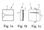
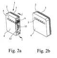
- the electrical connection and junction box according to the preferred embodiment of the invention, a housing 1 with side walls 2 and a lid 3. Furthermore, a bottom 4 of the housing 1 is provided which has an elongate recess 5. As can be seen in particular from FIG. 2 a, a connection device 6 provided in the housing 1 can be reached via this recess 5.
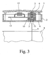
- connection device 6 is formed and arranged in detail, further Fig. 3 can be removed, which shows a section through the electrical connection and junction box according to the preferred embodiment of the invention along the line C-C.
- Fig. 3 is removable, that the connecting device 6 has a clamping device 7 in the form of two counter-acting springs. In this, when you put the electrical connection and junction box according to the preferred embodiment of the invention automatically apparent from Fig. 3 out of the solar cell module 8 led out thin conductor strips 9 introduced.
- a guide device 10 is provided in the housing 1 below the connecting device 6. This has a funnel-shaped in cross section insertion opening 11 which tapers in cross section, so that the conductor strips 9 are guided in the guide device 10 with little play in the transverse direction. In this way, a bending of the conductor strips 9 during insertion into the connecting device 6 is avoided, so that the force acting on the solar cell module when placing the electrical connection and junction box can act virtually completely in the longitudinal direction of the thin conductor strips 9.
- the connecting device 6 is connected to a printed circuit board 12, on which a plurality of bypass diodes 13 is arranged. These bypass diodes 13 have the function described above for securing the individual solar cells and are connected via the connecting device 6 and the thin conductor strips 9 with the individual solar cells of the solar cell module 8.
- the invention goes a completely new way in that the flexible thin conductor strips 9 are inserted not only from below into the housing 1 of the electrical connection and junction box, but also be introduced directly from below into the provided in the housing 1 connecting device 6.
- the connecting device 6 is arranged and designed, in this case in particular namely provided with a guide device 10 that automatically takes place when placing the electrical connection and junction box on the solar cell module 8 an introduction of the conductor strips 9 in the connection device 6.
Abstract
Description
- Die Erfindung betrifft eine elektrische Anschluß- und Verbindungsdose für ein Solarzellenmodul aus mit dünnen Leiterbändern angeschlossenen Solarzellen, mit einem Gehäuse und in dem Gehäuse vorgesehenen elektrischen oder/und elektronischen Einrichtungen sowie einer in dem Gehäuse vorgesehenen Anschlußvorrichtung.
- Da die Ausgangsspannung einzelner Solarzellen im allgemeinen zu gering ist, um elektrische Geräte, wie Haushaltsgeräte oder ähnliche Geräte, zu betreiben, werden im allgemeinen mehrere Solarzellen zu Solarzellenmodulen zusammengeschaltet. Dabei besteht einerseits die Möglichkeit der Reihenschaltung der Solarzellen und andererseits die Möglichkeit der Parallelschaltung der Solarzellen im Solarzellenmodul. Durch ein Parallelschalten der Solarzellen addieren sich die einzelnen Ströme der Solarzellen zu einem Gesamtstrom. Dabei sollten die parallelgeschalteten Solarzellen allerdings im wesentlichen die gleichen physikalischen Eigenschaften haben, so daß sich in der Praxis das Parallelschalten von Solarzellen kaum durchgesetzt hat, insbesondere auch da eine einzelne Solarzelle bereits einen Strom von einigen Ampere liefern kann.
- Bei der Zusammenstellung von Solarzellenmodulen mit einzelnen Solarzellen werden die Solarzellen daher häufig in Reihe geschaltet. Ein Problem kann sich dabei jedoch dann ergeben, wenn ein Solarzellenmodul partiell abgeschattet wird, also eine Solarzelle oder einzelne Solarzellen des Solarzellenmoduls weniger oder gar keine Sonnenbestrahlung erhalten. Der Grund für eine verringerte Sonnenbestrahlung kann z. B. in einer Verschmutzung der Solarzellen oder in Schattenwürfen von Bäumen, Gebäudeeinrichtungen oder Gebäuden liegen.
- Im Gegensatz zu einer Abschattung des Solarmoduls gleichmäßig über seine gesamte Fläche, die nur zu einer Leistungsverringerung insgesamt führt, ergibt sich bei einer partiellen Abschattung folgendes Problem: Durch die in Reihe geschalteten Solarzellen des Solarzellenmoduls fließt ein gemeinsamer Strom, wobei jede einzelne Solarzelle mit ihrer jeweiligen Spannung zur Gesamtspannung des Solarzellenmoduls beiträgt. Wird nun eine Solarzelle abgeschattet, so erzeugt diese keine Spannung mehr und setzt dem Stromfluß im Solarzellenmodul praktisch eine Diode in Sperrichtung entgegen. Dies bedeutet jedoch, daß das gesamte Modul keinen Strom mehr liefern kann, so daß die gesamte Funktion des Solarzellenmoduls beeinträchtigt ist.
- Außerdem gilt, daß an der abgeschatteten Solarzelle eine Spannung anliegt, die abhängig ist von der Position der abgeschatteten Solarzelle in der Reihenschaltung. Ist diese an der abgeschatteten Solarzelle anliegende Spannung größer als ihre Sperrspannung, so wird es in der Solarzelle zu einem Durchschlag und damit zu einer dauerhaften Beschädigung der Solarzelle kommen. Selbst wenn es zu keiner Beschädigung der Solarzelle durch einen Durchschlag kommen sollte, wird in der abgeschatteten Solarzelle eine große Verlustleistung umgesetzt, so daß sich die abgeschattete Solarzelle aufheizt. Auch eine solche Aufheizung kann zu Beschädigungen an der abgeschatteten Solarzelle sowie an den ihr benachbarten Solarzellen führen.
- Um die mit teilweise abgeschatteten Solarzellen verbundene Problematik zu vermeiden, werden häufig Dioden, sogenannte Bypass-Dioden, verwendet, die antiparallel zu den Solarzellen geschaltet werden. Auf diese Weise wird erreicht, daß eine abgeschattete Solarzelle zwar keinen Anteil mehr zur Gesamtspannung des Solarzellenmoduls leistet, der Stromfluß jedoch trotzdem erhalten bleibt. Das Solarzellenmodul zeigt somit lediglich eine verminderte Betriebspannung, fällt jedoch nicht vollständig aus. Außerdem wird in der abgeschatteten Solarzelle keine Leistung mehr umgesetzt, so daß eine Beschädigung der abgeschatteten Solarzelle vermieden werden kann.
- Grundsätzlich könnte jeder Solarzelle eines Solarzellenmoduls genau eine Diode zugeordnet sein. Häufig wird jedoch so vorgegangen, daß eine Mehrzahl hintereinander geschalteter Solarzellen jeweils durch eine gemeinsame Diode abgesichert wird. Elektrische Anschluß- und Verbindungsdosen, die für Solarzellenmodule verwendet werden, weisen somit im allgemeinen immer nocheine Mehrzahl von Bypass-Dioden auf. Darüber hinaus können in den elektrischen Anschluß- und Verbindungsdosen weitere elektrische oder/und elektronische Einrichtungen vorgesehen sein, so daß der elektrischen Anschluß- und Verbindungsdose zugeführte Leiter mit den elektrischen oder/und elektronischen Einrichtungen, wie den Bypass-Dioden, verbunden werden müssen.
- Die Solarzellen in einem Solarzellenmodul sind im allgemeinen mit dünnen Leiterbändern, sogenannten Strings, miteinander verbunden. Diese Leiterbänder weisen typischerweise eine Dicke von wenigen Zehntel Millimeters (ca. 0,3 mm) und eine Breite von einigen Millimetern (ca. 3-8 mm) auf. Diese die einzelnen Solarzellen des Solarzellenmoduls miteinander verbindenden Leiterbänder werden aus dem Solarzellenmodul heraus geführt, so daß die dünnen Leiterbänder direkt zu Anschlußzwecken verwendet werden können.
- Dazu werden die Leiterbänder typischerweise in eine solche elektrische Anschluß- und Verbindungsdose von unten her eingeführt, die einen abnehmbaren Deckel aufweist, so daß die einzelnen Leiterbänder von Hand in einer in dem Gehäuse der Anschluß- und Verbindungsdose vorgesehenen elektrischen Anschlußvorrichtung kontaktiert werden können. Dazu werden die vom Solarzellenmodul, relativ zum Gehäuse der Anschluß- und Verbindungsdose von unten her kommenden dünnen Leiterbänder im allgemeinen um 180° umgebogen, um dann von oben her kommend in der Anschlußvorrichtung angeschlossen zu werden. Ein solches Umbiegen ist ohne weiteres möglich, da die dünnen Leiterbänder, die typischerweise aus Metall bestehen, aufgrund ihrer Abmessungen, insbesondere nämlich ihrer geringen Dicke, sehr flexibel sind. Allerdings ist diese Vorgehensweise sehr aufwendig und zeitintensiv, und Anschlußfehler können nicht ohne weiteres vermieden werden.
- Es ist daher die Aufgabe der Erfindung, eine solche elektrische Anschluß- und Verbindungsdose für ein Solarzellenmodul anzugeben, mit der ein einfacher und sicherer Anschluß aus dem Solarzellenmodul herausgeführter dünner Leiterbänder ermöglicht wird.
- Ausgehend von der eingangs beschriebenen elektrischen Anschluß- und Verbindungsdose ist die zuvor hergeleitete und aufgezeigte Aufgabe dadurch gelöst, daß die Anschlußvorrichtung derart ausgebildet und angeordnet ist, daß aus dem Solarzellenmodul herausgeführte dünne Leiterbänder beim Aufsetzen der Anschluß- und Verbindungsdose auf das Solarzellenmodul automatisch von unten her in die elektrische Anschlußvorrichtung eingeführt werden.
- Die Erfindung geht also einen völlig neuen Weg, indem aus dem Solarzellenmodul herausgeführte und zum Anschluß der Solarzellen dienende dünne Leiterbänder beim Aufsetzen der Anschluß- und Verbindungsdose auf das Solarzellenmodul einerseits automatisch, also ohne zusätzliche Handarbeit, und andererseits direkt von unten her in die elektrische Anschlußvorrichtung eingeführt werden. Durch die Erfindung wird damit das aufwendige, aus dem Stand der Technik bekannte Vorgehen vermieden, die dünnen Leiterbänder zum Anschließen der Solarzellen in der Anschluß- und Verbindungsdose erst nach oben zu führen und dann um bis zu 180° umzubiegen, um sie der Anschlußvorrichtung zuzuführen. Beim Anschließen der Solarzellen des Solarzellenmoduls ist der erforderliche Aufwand also durch die Erfindung erheblich verringert, und insbesondere können praktisch keine Falschkontaktierungen mehr vorkommen.
- Grundsätzlich sind für die erfindungsgemäße Anschluß- und Verbindungsdose verschiedene Typen von Anschlußvorrichtungen verwendbar. Gemäß einer bevorzugten Weiterbildung der Erfindung ist jedoch vorgesehen, daß die elektrische Anschlußvorrichtung eine Klemmeinrichtung aufweist. Dabei kann gemäß einer bevorzugten Weiterbildung der Erfindung insbesondere vorgesehen sein, daß die Klemmeinrichtung Anschlußfederelemente zur Herstellung eines Klemmkontakts mit den dünnen Leiterbändern aufweist. Diese Anschlußfederelemente weisen wenigstens eine Feder vorzugsweise jedoch zwei gegeneinander wirkende Federn, z. B. in Form von Blattfedern, auf, die aufgrund ihrer Federkraft auf die in die Anschlußvorrichtung eingeschobenen Leiterbänder wirken und damit den erforderlichen elektrischen Kontakt herstellen.
- Grundsätzlich kann die Anschlußvorrichtung derart in dem Gehäuse der elektrischen Anschluß- und Verbindungsdose angeordnet sein, daß die aus dem Solarzellenmodul herausgeführten dünnen Leiterbänder beim Aufsetzen der Anschluß- und Verbindungsdose auf das Solarzellenmodul automatisch von unten her in die elektrische Anschlußvorrichtung eingeführt werden, ohne daß zusätzliche Einrichtungen vorgesehen sind, die das Einführen der Leiterbänder in die Anschlußvorrichtung unterstützen. Gemäß einer bevorzugten Weiterbildung der Erfindung ist jedoch vorgesehen, daß unterhalb der Klemmeinrichtung eine Führungseinrichtung zum geführten Einführen der dünnen Leiterbänder in die Klemmeinrichtung beim Aufsetzen der Anschluß- und Verbindungsdose auf das Solarzellenmodul vorgesehen ist. Eine solche Führungseinrichtung dient im wesentlichen dazu, ein Knicken oder Falten der Leiterbänder beim Einführen zu vermeiden, so daß die in Längsrichtung der dünnen Leiterbänder wirkenden Kraft beim Einführen derselben in die Anschlußvorrichtung auch tatsächlich in die gewünschte Richtung wirkt und nicht zu einer Deformation, nämlich zu dem angesprochenen Knicken oder Falten der dünnen Leiterbänder führt. Dabei kann z. B. eine solche Führungseinrichtung vorgesehen sein, die den Querschnittsabmessungen der dünnen Leiterbänder entsprechende Öffnungen aufweist, so daß beim Aufsetzen der elektrischen Anschluß- und Verbindungsdose auf das Solarzellenmodul die dünnen Leiterbänder in diesen Öffnungen mit geringem Spiel geführt werden, die Innenwände der Öffnungen also der eigentlichen Führung und damit der Verhinderung des Knickens oder Faltens dienen.
- Der erfindungsgemäße Ansatz, daß die aus dem Solarzellenmodul herausgeführten dünnen Leiterbänder beim Aufsetzen der Anschluß- und Verbindungsdose auf das Solarzellenmodul einerseits automatisch und andererseits von unten her in die elektrische Anschlußvorrichtung eingeführt werden, eröffnet noch einen weiteren Vorteil. Gemäß einer bevorzugten Weiterbildung der Erfindung ist nämlich vorgesehen, daß das Gehäuse Seitenwände und einen Deckel aufweist, wobei die Seitenwände und der Deckel einstückig ausgebildet sind. Mit anderen Worten ist es bei der erfindungsgemäßen elektrischen Anschluß- und Verbindungsdose nicht mehr zwingend erforderlich, einen abnehmbaren Deckel vorzusehen. Schließlich erfolgt das Einführen der dünnen Leiterbänder in die Anschlußvorrichtung automatisch, so daß der Innenraum der elektrischen Anschluß- und Verbindungsdose nicht von oben her für ein Anschließen von Hand zugänglich sein muß.
- Zur Erfindung gehört auch eine derartige Verwendung einer elektrischen Anschluß- und Verbindungsdose mit Anschlußvorrichtungen zum Anschließen eines Solarzellenmoduls aus mit dünnen Leiterbändern miteinander verbundenen Solarzellen, bei der aus dem Solarzellenmodul austretende dünne Leiterbänder beim Aufsetzen der Anschluß- und Verbindungsdose auf das Solarzellenmodul automatisch von unten her in die Anschlußvorrichtung eingeführt werden.
- Dabei ist gemäß einer bevorzugten Weiterbildung der Erfindung vorgesehen, daß die elektrische Anschlußvorrichtung eine Klemmeinrichtung aufweist, so daß die dünnen Leiterbänder beim Aufsetzen der Anschluß- und Verbindungsdose auf das Solarzellenmodul von unten her in der Anschlußvorrichtung verklemmt werden. Insbesondere kann dabei vorgesehen sein, daß die Klemmeinrichtung Anschlußfederelemente zur Herstellung eines Klemmkontakts mit den dünnen Leiterbändern aufweist. Schließlich kann vorgesehen sein, daß die dünnen Leiterbänder beim Aufsetzen der Anschluß- und Verbindungsdose auf das Solarzellenmodul geführt werden, um das weiter oben schon angesprochene Umknicken oder Falten der Leiterbänder und damit ein vorschriftsmäßiges Einführen der Leiterbänder in die Klemmeinrichtung zu gewährleisten.
- Im einzelnen gibt es eine Vielzahl von Möglichkeiten, die erfindungsgemäße elektrische Anschluß- und Verbindungsdose auszugestalten und weiterzubilden, wozu einerseits auf die abhängigen Patentansprüche und andererseits auf die nachfolgende detaillierte Beschreibung eines bevorzugten Ausführungsbeispiels der Erfindung unter Bezugnahme auf die Zeichnung verwiesen wird. In der Zeichnung zeigt
- Fig. 1a - c
- eine elektrische Anschluß- und Verbindungsdose für ein Solarzellenmodul gemäß einem bevorzugten Ausführungsbeispiel der Erfindung in einer Ansicht von oben, von der Seite bzw. von unten,
- Fig. 2a, b
- perspektivische Ansichten der elektrischen Anschluß- und Verbindungsdose gemäß dem bevorzugten Ausführungsbeispiel der Erfindung, teilweise im Schnitt,
- Fig. 3
- einen Schnitt durch die elektrische Anschluß- und Verbindungsdose gemäß dem bevorzugten Ausführungsbeispiel der Erfindung und
- Fig. 4
- die Anschlußvorrichtung der elektrischen Anschluß- und Verbindungsdose gemäß dem bevorzugten Ausführungsbeispiel der Erfindung.
- Wie aus Fig. 1 ersichtlich, weist die elektrische Anschluß- und Verbindungsdose gemäß dem bevorzugten Ausführungsbeispiel der Erfindung ein Gehäuse 1 mit Seitenwänden 2 und einen Deckel 3 auf. Weiterhin ist ein Boden 4 des Gehäuses 1 vorgesehen, der eine langgestreckte Ausnehmung 5 aufweist. Wie insbesondere Fig. 2a entnehmbar, ist über diese Ausnehmung 5 eine in dem Gehäuse 1 vorgesehene Anschlußvorrichtung 6 erreichbar.
- Wie diese Anschlußvorrichtung 6 im einzelnen ausgebildet und angeordnet ist, ist weiterhin Fig. 3 entnehmbar, die einen Schnitt durch die elektrische Anschluß- und Verbindungsdose gemäß dem bevorzugten Ausführungsbeispiel der Erfindung längs der Linie C-C zeigt. Fig. 3 ist dabei entnehmbar, daß die Anschlußvorrichtung 6 eine Klemmeinrichtung 7 in Form von zwei gegeneinanderwirkenden Federn aufweist. In diese werden beim Aufsetzen der elektrischen Anschluß- und Verbindungsdose gemäß dem bevorzugten Ausführungsbeispiel der Erfindung automatisch die auch aus Fig. 3 ersichtlichen aus dem Solarzellenmodul 8 herausgeführten dünnen Leiterbänder 9 eingeführt.
- Um beim Einführen der Leiterbänder 9 in die Anschlußvorrichtung 6 ein Deformieren, insbesondere ein Umknicken oder Falten der Leiterbänder 9 zu vermeiden, ist in dem Gehäuse 1 unterhalb der Anschlußvorrichtung 6 eine Führungseinrichtung 10 vorgesehen. Diese weist eine im Querschnitt trichterförmige Einführungsöffnung 11 auf, die sich im Querschnitt verjüngt, so daß die Leiterbänder 9 in der Führungseinrichtung 10 mit geringem Spiel in Querrichtung geführt werden. Auf diese Weise wird ein Umknicken der Leiterbänder 9 beim Einführen in die Anschlußvorrichtung 6 vermieden, so daß die beim Aufsetzen der elektrischen Anschluß- und Verbindungsdose auf das Solarzellenmodul wirkende Kraft praktisch vollständig in Längsrichtung der dünnen Leiterbänder 9 wirken kann.
- Wie Fig. 3 und insbesondere auch Fig. 4 entnehmbar, ist die Anschlußvorrichtung 6 mit einer Leiterplatte 12 verbunden, auf der eine Mehrzahl von Bypass-Dioden 13 angeordnet ist. Diese Bypass-Dioden 13 haben die eingangs beschriebene Funktion zur Absicherung der einzelnen Solarzellen und sind dazu über die Anschlußvorrichtung 6 und die dünnen Leiterbänder 9 mit den einzelnen Solarzellen des Solarzellenmoduls 8 verbunden.
- Wie der obigen Beschreibung der elektrischen Anschluß- und Verbindungsdose gemäß dem bevorzugten Ausführungsbeispiel der Erfindung entnehmbar, geht die Erfindung einen völlig neuen Weg, indem die flexiblen dünnen Leiterbänder 9 nicht nur von unten her in das Gehäuse 1 der elektrischen Anschluß- und Verbindungsdose eingeführt werden, sondern auch direkt von unten her in die in dem Gehäuse 1 vorgesehen Anschlußvorrichtung 6 eingeführt werden. Dabei ist die Anschlußvorrichtung 6 derart angeordnet und ausgebildet, vorliegend insbesondere nämlich mit einer Führungseinrichtung 10 versehen, daß beim Aufsetzen der elektrischen Anschluß- und Verbindungsdose auf das Solarzellenmodul 8 automatisch eine Einführung der Leiterbänder 9 in die Anschlußvorrichtung 6 erfolgt. Damit wird das Anschließen der einzelnen Solarzellen des Solarzellenmoduls 8 deutlich erleichtert, und insbesondere können Fehlkontaktierungen vermieden werden.
Claims (9)
- Elektrische Anschluß- und Verbindungsdose für ein Solarzellenmodul (8) aus mit dünnen Leiterbändern (9) angeschlossenen Solarzellen, mit einem Gehäuse (1) und in dem Gehäuse (1) vorgesehenen elektrischen oder/und elektronischen Einrichtungen sowie einer in dem Gehäuse (1) vorgesehenen elektrischen Anschlußvorrichtung (6), dadurch gekennzeichnet, daß die Anschlußvorrichtung (6) derart ausgebildet und angeordnet ist, daß aus dem Solarzellenmodul (8) herausgeführte dünne Leiterbänder (9) beim Aufsetzen der Anschluß- und Verbindungsdose auf das Solarzellenmodul (8) automatisch von unten her in die elektrische Anschlußvorrichtung (6) eingeführt werden.
- Elektrische Anschluß- und Verbindungsdose nach Anspruch 1, dadurch gekennzeichnet, daß die elektrische Anschlußvorrichtung (6) eine Klemmeinrichtung (7) aufweist.
- Elektrische Anschluß- und Verbindungsdose nach Anspruch 2, dadurch gekennzeichnet, daß die Klemmeinrichtung (7) Anschlußfederelemente zur Herstellung eines Klemmkontaktes mit den dünnen Leiterbändern (9) aufweist.
- Elektrische Anschluß- und Verbindungsdose nach einem der Ansprüche 1 bis 3, dadurch gekennzeichnet, daß unterhalb der Anschlußvorrichtung (6) eine Führungseinrichtung (10) zum geführten Einführen der dünnen Leiterbänder (9) in die Anschlußvorrichtung beim Aufsetzen der Anschluß- und Verbindungsdose auf das Solarzellenmodul (8) vorgesehen ist.
- Elektrische Anschluß- und Verbindungsdose nach einem der Ansprüche 1 bis 4, dadurch gekennzeichnet, daß das Gehäuse (1) Seitenwände (2) und einen Deckel (3) aufweist, wobei die Seitenwände (2) und der Deckel (3) einstückig ausgebildet sind.
- Verwendung einer elektrischen Anschluß- und Verbindungsdose mit einer Anschlußvorrichtung (6) zum Anschließen eines Solarzellenmoduls (8) aus mit dünnen Leiterbändern (9) miteinander verbundenen Solarzellen, insbesondere nach einem der Ansprüche 1 bis 5, dadurch gekennzeichnet, daß aus dem Solarzellenmodul (8) herausgeführte dünne Leiterbänder (9) beim Aufsetzen der Anschluß- und Verbindungsdose auf das Solarzellenmodul (8) automatisch von unten her in die Anschlußvorrichtung (6) eingeführt werden.
- Verwendung nach Anspruch 6, dadurch gekennzeichnet, daß die elektrische Anschlußvorrichtung (6) eine Klemmeinrichtung (7) aufweist, so daß die dünnen Leiterbänder (9) beim Aufsetzen der Anschluß- und Verbindungsdose auf das Solarzellenmodul (8) von unten her in der Anschlußvorrichtung (6) verklemmt werden.
- Verwendung nach Anspruch 7, dadurch gekennzeichnet, daß die Klemmeinrichtung (7) Anschlußfederelemente zur Herstellung eines Klemmkontaktes mit den dünnen Leiterbändern (9) aufweist.
- Verwendung nach einem der Ansprüche 6 bis 8, dadurch gekennzeichnet, daß unterhalb der Anschlußvorrichtung (6) eine Führungseinrichtung (10) vorgesehen ist, so daß beim Aufsetzen der Anschluß- und Verbindungsdose auf das Solarzellenmodul (8) eine Führung der dünnen Leiterbänder (9) erfolgt.
Priority Applications (3)
| Application Number | Priority Date | Filing Date | Title |
|---|---|---|---|
| AT04029825T ATE527694T1 (de) | 2004-12-16 | 2004-12-16 | Elektrische anschluss- und verbindungsdose für ein solarzellenmodul |
| EP04029825A EP1672702B1 (de) | 2004-12-16 | 2004-12-16 | Elektrische Anschluss- und Verbindungsdose für ein Solarzellenmodul |
| ES04029825T ES2371638T3 (es) | 2004-12-16 | 2004-12-16 | Caja de conexión y unión eléctrica para un módulo de células solares. |
Applications Claiming Priority (1)
| Application Number | Priority Date | Filing Date | Title |
|---|---|---|---|
| EP04029825A EP1672702B1 (de) | 2004-12-16 | 2004-12-16 | Elektrische Anschluss- und Verbindungsdose für ein Solarzellenmodul |
Publications (2)
| Publication Number | Publication Date |
|---|---|
| EP1672702A1 true EP1672702A1 (de) | 2006-06-21 |
| EP1672702B1 EP1672702B1 (de) | 2011-10-05 |
Family
ID=34927811
Family Applications (1)
| Application Number | Title | Priority Date | Filing Date |
|---|---|---|---|
| EP04029825A Not-in-force EP1672702B1 (de) | 2004-12-16 | 2004-12-16 | Elektrische Anschluss- und Verbindungsdose für ein Solarzellenmodul |
Country Status (3)
| Country | Link |
|---|---|
| EP (1) | EP1672702B1 (de) |
| AT (1) | ATE527694T1 (de) |
| ES (1) | ES2371638T3 (de) |
Cited By (12)
| Publication number | Priority date | Publication date | Assignee | Title |
|---|---|---|---|---|
| WO2008095670A1 (de) | 2007-02-05 | 2008-08-14 | Phoenix Contact Gmbh & Co. Kg | Anschluss- und verbindungsdose für ein solarmodul |
| WO2008095668A1 (de) * | 2007-02-05 | 2008-08-14 | Phoenix Contact Gmbh & Co. Kg | Anschluss- und verbindungsdose für ein solarmodul |
| EP1976025A1 (de) | 2007-03-28 | 2008-10-01 | Günther Spelsberg GmbH | Paneldose |
| EP1976027A2 (de) | 2007-03-28 | 2008-10-01 | Günther Spelsberg GmbH & Co. KG | Paneldose |
| EP1976026A2 (de) | 2007-03-28 | 2008-10-01 | Günther Spelsberg GmbH & Co. KG | Paneldose |
| DE102007020843A1 (de) | 2007-03-28 | 2008-10-02 | Günther Spelsberg GmbH & Co. KG | Paneldose |
| DE102007020846A1 (de) | 2007-03-28 | 2008-10-09 | Günther Spelsberg GmbH & Co. KG | Paneldose |
| JP2010518564A (ja) * | 2007-02-05 | 2010-05-27 | フェニックス コンタクト ゲーエムベーハー ウント コムパニー カーゲー | 太陽光発電モジュール用接続箱 |
| DE102009030141A1 (de) | 2009-06-24 | 2010-12-30 | A. Raymond Et Cie | Vorrichtung zum elektrischen Kontaktieren von Leiterbändern von Solarmodulen |
| US8435056B2 (en) | 2009-04-16 | 2013-05-07 | Enphase Energy, Inc. | Apparatus for coupling power generated by a photovoltaic module to an output |
| USD734653S1 (en) | 2012-11-09 | 2015-07-21 | Enphase Energy, Inc. | AC module mounting bracket |
| US9118273B2 (en) | 2011-07-18 | 2015-08-25 | Enphase Energy, Inc. | Resilient mounting assembly for photovoltaic modules |
Citations (4)
| Publication number | Priority date | Publication date | Assignee | Title |
|---|---|---|---|---|
| US5503684A (en) * | 1994-12-30 | 1996-04-02 | Silicon Energy Corporation | Termination system for solar panels |
| EP0867947A2 (de) * | 1997-03-27 | 1998-09-30 | Canon Kabushiki Kaisha | Solarzellenmodul |
| EP1041647A1 (de) * | 1999-03-30 | 2000-10-04 | Kaneka Corporation | Photovoltaisches Modul und Energieerzeugungssystem |
| EP1289069A2 (de) * | 2001-08-27 | 2003-03-05 | Günther Spelsberg GmbH & Co. KG | Anschluss- und Verbindungsklemmenblock |
-
2004
- 2004-12-16 ES ES04029825T patent/ES2371638T3/es active Active
- 2004-12-16 AT AT04029825T patent/ATE527694T1/de active
- 2004-12-16 EP EP04029825A patent/EP1672702B1/de not_active Not-in-force
Patent Citations (4)
| Publication number | Priority date | Publication date | Assignee | Title |
|---|---|---|---|---|
| US5503684A (en) * | 1994-12-30 | 1996-04-02 | Silicon Energy Corporation | Termination system for solar panels |
| EP0867947A2 (de) * | 1997-03-27 | 1998-09-30 | Canon Kabushiki Kaisha | Solarzellenmodul |
| EP1041647A1 (de) * | 1999-03-30 | 2000-10-04 | Kaneka Corporation | Photovoltaisches Modul und Energieerzeugungssystem |
| EP1289069A2 (de) * | 2001-08-27 | 2003-03-05 | Günther Spelsberg GmbH & Co. KG | Anschluss- und Verbindungsklemmenblock |
Cited By (21)
| Publication number | Priority date | Publication date | Assignee | Title |
|---|---|---|---|---|
| JP2010518564A (ja) * | 2007-02-05 | 2010-05-27 | フェニックス コンタクト ゲーエムベーハー ウント コムパニー カーゲー | 太陽光発電モジュール用接続箱 |
| WO2008095668A1 (de) * | 2007-02-05 | 2008-08-14 | Phoenix Contact Gmbh & Co. Kg | Anschluss- und verbindungsdose für ein solarmodul |
| WO2008095669A1 (de) * | 2007-02-05 | 2008-08-14 | Phoenix Contact Gmbh & Co. Kg | Anschluss- und verbindungsdose für ein solarmodul |
| US8366471B2 (en) | 2007-02-05 | 2013-02-05 | Phoenix Contact Gmbh & Co. Kg | Connection and junction box for a solar module |
| CN101606294B (zh) * | 2007-02-05 | 2013-01-02 | 菲尼克斯电气公司 | 用于太阳能模块的端子接线箱 |
| WO2008095670A1 (de) | 2007-02-05 | 2008-08-14 | Phoenix Contact Gmbh & Co. Kg | Anschluss- und verbindungsdose für ein solarmodul |
| CN101606295B (zh) * | 2007-02-05 | 2012-05-02 | 菲尼克斯电气公司 | 用于太阳能模块的端子接线箱 |
| US8033859B2 (en) | 2007-02-05 | 2011-10-11 | Phoenix Contact Gmbh & Co. Kg | Connection and junction box for a solar module |
| US7931488B2 (en) | 2007-02-05 | 2011-04-26 | Phoenix Contact Gmbh & Co. Kg | Connection and junction box for a solar module |
| EP1976026A2 (de) | 2007-03-28 | 2008-10-01 | Günther Spelsberg GmbH & Co. KG | Paneldose |
| DE102007020845A1 (de) | 2007-03-28 | 2008-10-09 | Günther Spelsberg GmbH & Co. KG | Paneldose |
| DE102007020846A1 (de) | 2007-03-28 | 2008-10-09 | Günther Spelsberg GmbH & Co. KG | Paneldose |
| US8097818B2 (en) | 2007-03-28 | 2012-01-17 | Gunther Spelsberg Gmbh & Co. Kg | Panel box |
| DE102007020843A1 (de) | 2007-03-28 | 2008-10-02 | Günther Spelsberg GmbH & Co. KG | Paneldose |
| EP1976027A2 (de) | 2007-03-28 | 2008-10-01 | Günther Spelsberg GmbH & Co. KG | Paneldose |
| EP1976025A1 (de) | 2007-03-28 | 2008-10-01 | Günther Spelsberg GmbH | Paneldose |
| US8435056B2 (en) | 2009-04-16 | 2013-05-07 | Enphase Energy, Inc. | Apparatus for coupling power generated by a photovoltaic module to an output |
| DE102009030141A1 (de) | 2009-06-24 | 2010-12-30 | A. Raymond Et Cie | Vorrichtung zum elektrischen Kontaktieren von Leiterbändern von Solarmodulen |
| US9118273B2 (en) | 2011-07-18 | 2015-08-25 | Enphase Energy, Inc. | Resilient mounting assembly for photovoltaic modules |
| US11515835B2 (en) | 2011-07-18 | 2022-11-29 | Enphase Energy, Inc. | Resilient mounting assembly for photovoltaic modules |
| USD734653S1 (en) | 2012-11-09 | 2015-07-21 | Enphase Energy, Inc. | AC module mounting bracket |
Also Published As
| Publication number | Publication date |
|---|---|
| EP1672702B1 (de) | 2011-10-05 |
| ES2371638T3 (es) | 2012-01-05 |
| ATE527694T1 (de) | 2011-10-15 |
Similar Documents
| Publication | Publication Date | Title |
|---|---|---|
| DE10358140B4 (de) | Elektrische Anschluß- und Verbindungsdose für ein Solarzellenmodul | |
| EP1729348B1 (de) | Elektrische Anschluss- und Verbindungsdose für ein Solarzellenmodul | |
| EP2232582B1 (de) | Anschlussdose, verwendung, solarpaneel, kontaktelement, und verfahren | |
| EP1672702B1 (de) | Elektrische Anschluss- und Verbindungsdose für ein Solarzellenmodul | |
| DE102007020843A1 (de) | Paneldose | |
| EP3047540B1 (de) | Klemmkäfig für eine direktsteckklemme | |
| DE102008010026A1 (de) | Elektrische Anschluss- und Verbindungsdose für ein Solarzellenmodul | |
| DE202010018062U1 (de) | Anschluss- und Verbindungsvorrichtung | |
| DE102007031351B4 (de) | Verbindungsvorrichtung zur Verbindung eines ersten elektrischen Leiters mit einem elektrischen Leiter eines photovoltaischen Solarmoduls | |
| DE69919257T2 (de) | Kabelbaumanordnung | |
| EP1496577B1 (de) | Elektrische Anschluss- und Verbindungsdose | |
| DE102018202542A1 (de) | Klemme | |
| DE102017212186B4 (de) | Mit Gießharz versiegelte Leistungshalbleiter-Einrichtung | |
| EP2056357A2 (de) | Anordnung mit einem Solarzellenmodul und einem Rahmen | |
| EP1976026A2 (de) | Paneldose | |
| DE19963268B4 (de) | Sicherungsleiste, zugehöriger Sicherungskasten und Herstellungsverfahren | |
| EP1727240A1 (de) | Elektrische Anschluss- und Verbindungsdose | |
| DE102007020846A1 (de) | Paneldose | |
| DE60318823T2 (de) | Thermisch betätigter schalter | |
| EP1976027B1 (de) | Paneldose | |
| WO2012168330A1 (de) | Photovoltaik-paneldose mit verbesserten aussenanschlüssen | |
| DE102015218526A1 (de) | Anschlussanordnung für ein Solarmodul | |
| DE19944427A1 (de) | Kabelverbindung zwischen Flachbandkabel und Rundbandkabel bzw. Rundkabel und Verfahren zu deren Herstellung | |
| DE102008039932A1 (de) | Verbindungsvorrichtung zur Verbindung eines elektrischen Leiters mit einem Solarmodul und Verfahren zu ihrer Herstellung, sowie Solarmodul mit einer solchen Verbindungsvorrichtung | |
| DE1415857A1 (de) | Elektrischer Kabel-Verteilerkasten |
Legal Events
| Date | Code | Title | Description |
|---|---|---|---|
| PUAI | Public reference made under article 153(3) epc to a published international application that has entered the european phase |
Free format text: ORIGINAL CODE: 0009012 |
|
| AK | Designated contracting states |
Kind code of ref document: A1 Designated state(s): AT BE BG CH CY CZ DE DK EE ES FI FR GB GR HU IE IS IT LI LT LU MC NL PL PT RO SE SI SK TR |
|
| AX | Request for extension of the european patent |
Extension state: AL BA HR LV MK YU |
|
| 17P | Request for examination filed |
Effective date: 20061005 |
|
| AKX | Designation fees paid |
Designated state(s): AT BE BG CH CY CZ DE DK EE ES FI FR GB GR HU IE IS IT LI LT LU MC NL PL PT RO SE SI SK TR |
|
| 17Q | First examination report despatched |
Effective date: 20070309 |
|
| GRAP | Despatch of communication of intention to grant a patent |
Free format text: ORIGINAL CODE: EPIDOSNIGR1 |
|
| GRAS | Grant fee paid |
Free format text: ORIGINAL CODE: EPIDOSNIGR3 |
|
| GRAA | (expected) grant |
Free format text: ORIGINAL CODE: 0009210 |
|
| RIN1 | Information on inventor provided before grant (corrected) |
Inventor name: NIELECK, UDO Inventor name: QUARDT, DIRK, DIPL.-ING. Inventor name: ZBOROWSKI, ZBIGNIEW, DIPL.-ING. Inventor name: WASSERFUHR, FRIEDEL, DIPL.-ING. |
|
| AK | Designated contracting states |
Kind code of ref document: B1 Designated state(s): AT BE BG CH CY CZ DE DK EE ES FI FR GB GR HU IE IS IT LI LT LU MC NL PL PT RO SE SI SK TR |
|
| REG | Reference to a national code |
Ref country code: GB Ref legal event code: FG4D Free format text: NOT ENGLISH |
|
| REG | Reference to a national code |
Ref country code: CH Ref legal event code: EP |
|
| REG | Reference to a national code |
Ref country code: IE Ref legal event code: FG4D |
|
| REG | Reference to a national code |
Ref country code: DE Ref legal event code: R096 Ref document number: 502004012928 Country of ref document: DE Effective date: 20111229 |
|
| REG | Reference to a national code |
Ref country code: ES Ref legal event code: FG2A Ref document number: 2371638 Country of ref document: ES Kind code of ref document: T3 Effective date: 20120105 |
|
| REG | Reference to a national code |
Ref country code: NL Ref legal event code: VDEP Effective date: 20111005 |
|
| PGFP | Annual fee paid to national office [announced via postgrant information from national office to epo] |
Ref country code: CH Payment date: 20111227 Year of fee payment: 8 |
|
| PG25 | Lapsed in a contracting state [announced via postgrant information from national office to epo] |
Ref country code: SI Free format text: LAPSE BECAUSE OF FAILURE TO SUBMIT A TRANSLATION OF THE DESCRIPTION OR TO PAY THE FEE WITHIN THE PRESCRIBED TIME-LIMIT Effective date: 20111005 |
|
| LTIE | Lt: invalidation of european patent or patent extension |
Effective date: 20111005 |
|
| REG | Reference to a national code |
Ref country code: GR Ref legal event code: EP Ref document number: 20110403053 Country of ref document: GR Effective date: 20120206 |
|
| PG25 | Lapsed in a contracting state [announced via postgrant information from national office to epo] |
Ref country code: IS Free format text: LAPSE BECAUSE OF FAILURE TO SUBMIT A TRANSLATION OF THE DESCRIPTION OR TO PAY THE FEE WITHIN THE PRESCRIBED TIME-LIMIT Effective date: 20120205 Ref country code: LT Free format text: LAPSE BECAUSE OF FAILURE TO SUBMIT A TRANSLATION OF THE DESCRIPTION OR TO PAY THE FEE WITHIN THE PRESCRIBED TIME-LIMIT Effective date: 20111005 |
|
| REG | Reference to a national code |
Ref country code: IE Ref legal event code: FD4D |
|
| PG25 | Lapsed in a contracting state [announced via postgrant information from national office to epo] |
Ref country code: NL Free format text: LAPSE BECAUSE OF FAILURE TO SUBMIT A TRANSLATION OF THE DESCRIPTION OR TO PAY THE FEE WITHIN THE PRESCRIBED TIME-LIMIT Effective date: 20111005 Ref country code: PT Free format text: LAPSE BECAUSE OF FAILURE TO SUBMIT A TRANSLATION OF THE DESCRIPTION OR TO PAY THE FEE WITHIN THE PRESCRIBED TIME-LIMIT Effective date: 20120206 Ref country code: SE Free format text: LAPSE BECAUSE OF FAILURE TO SUBMIT A TRANSLATION OF THE DESCRIPTION OR TO PAY THE FEE WITHIN THE PRESCRIBED TIME-LIMIT Effective date: 20111005 |
|
| PG25 | Lapsed in a contracting state [announced via postgrant information from national office to epo] |
Ref country code: CY Free format text: LAPSE BECAUSE OF FAILURE TO SUBMIT A TRANSLATION OF THE DESCRIPTION OR TO PAY THE FEE WITHIN THE PRESCRIBED TIME-LIMIT Effective date: 20111005 |
|
| BERE | Be: lapsed |
Owner name: GUNTHER SPELSBERG G.M.B.H. & CO. KG Effective date: 20111231 |
|
| PG25 | Lapsed in a contracting state [announced via postgrant information from national office to epo] |
Ref country code: CZ Free format text: LAPSE BECAUSE OF FAILURE TO SUBMIT A TRANSLATION OF THE DESCRIPTION OR TO PAY THE FEE WITHIN THE PRESCRIBED TIME-LIMIT Effective date: 20111005 Ref country code: SK Free format text: LAPSE BECAUSE OF FAILURE TO SUBMIT A TRANSLATION OF THE DESCRIPTION OR TO PAY THE FEE WITHIN THE PRESCRIBED TIME-LIMIT Effective date: 20111005 Ref country code: BG Free format text: LAPSE BECAUSE OF FAILURE TO SUBMIT A TRANSLATION OF THE DESCRIPTION OR TO PAY THE FEE WITHIN THE PRESCRIBED TIME-LIMIT Effective date: 20120105 Ref country code: DK Free format text: LAPSE BECAUSE OF FAILURE TO SUBMIT A TRANSLATION OF THE DESCRIPTION OR TO PAY THE FEE WITHIN THE PRESCRIBED TIME-LIMIT Effective date: 20111005 Ref country code: IE Free format text: LAPSE BECAUSE OF FAILURE TO SUBMIT A TRANSLATION OF THE DESCRIPTION OR TO PAY THE FEE WITHIN THE PRESCRIBED TIME-LIMIT Effective date: 20111005 Ref country code: MC Free format text: LAPSE BECAUSE OF NON-PAYMENT OF DUE FEES Effective date: 20111231 Ref country code: EE Free format text: LAPSE BECAUSE OF FAILURE TO SUBMIT A TRANSLATION OF THE DESCRIPTION OR TO PAY THE FEE WITHIN THE PRESCRIBED TIME-LIMIT Effective date: 20111005 |
|
| PLBE | No opposition filed within time limit |
Free format text: ORIGINAL CODE: 0009261 |
|
| STAA | Information on the status of an ep patent application or granted ep patent |
Free format text: STATUS: NO OPPOSITION FILED WITHIN TIME LIMIT |
|
| PG25 | Lapsed in a contracting state [announced via postgrant information from national office to epo] |
Ref country code: RO Free format text: LAPSE BECAUSE OF FAILURE TO SUBMIT A TRANSLATION OF THE DESCRIPTION OR TO PAY THE FEE WITHIN THE PRESCRIBED TIME-LIMIT Effective date: 20111005 Ref country code: PL Free format text: LAPSE BECAUSE OF FAILURE TO SUBMIT A TRANSLATION OF THE DESCRIPTION OR TO PAY THE FEE WITHIN THE PRESCRIBED TIME-LIMIT Effective date: 20111005 |
|
| 26N | No opposition filed |
Effective date: 20120706 |
|
| GBPC | Gb: european patent ceased through non-payment of renewal fee |
Effective date: 20120105 |
|
| PG25 | Lapsed in a contracting state [announced via postgrant information from national office to epo] |
Ref country code: GB Free format text: LAPSE BECAUSE OF NON-PAYMENT OF DUE FEES Effective date: 20120105 Ref country code: BE Free format text: LAPSE BECAUSE OF NON-PAYMENT OF DUE FEES Effective date: 20111231 |
|
| REG | Reference to a national code |
Ref country code: DE Ref legal event code: R097 Ref document number: 502004012928 Country of ref document: DE Effective date: 20120706 |
|
| PG25 | Lapsed in a contracting state [announced via postgrant information from national office to epo] |
Ref country code: LU Free format text: LAPSE BECAUSE OF NON-PAYMENT OF DUE FEES Effective date: 20111216 |
|
| PG25 | Lapsed in a contracting state [announced via postgrant information from national office to epo] |
Ref country code: FI Free format text: LAPSE BECAUSE OF FAILURE TO SUBMIT A TRANSLATION OF THE DESCRIPTION OR TO PAY THE FEE WITHIN THE PRESCRIBED TIME-LIMIT Effective date: 20111005 |
|
| REG | Reference to a national code |
Ref country code: CH Ref legal event code: PL |
|
| REG | Reference to a national code |
Ref country code: AT Ref legal event code: MM01 Ref document number: 527694 Country of ref document: AT Kind code of ref document: T Effective date: 20121216 |
|
| REG | Reference to a national code |
Ref country code: GR Ref legal event code: ML Ref document number: 20110403053 Country of ref document: GR Effective date: 20130703 |
|
| PG25 | Lapsed in a contracting state [announced via postgrant information from national office to epo] |
Ref country code: TR Free format text: LAPSE BECAUSE OF FAILURE TO SUBMIT A TRANSLATION OF THE DESCRIPTION OR TO PAY THE FEE WITHIN THE PRESCRIBED TIME-LIMIT Effective date: 20111005 |
|
| PG25 | Lapsed in a contracting state [announced via postgrant information from national office to epo] |
Ref country code: AT Free format text: LAPSE BECAUSE OF NON-PAYMENT OF DUE FEES Effective date: 20121216 Ref country code: CH Free format text: LAPSE BECAUSE OF NON-PAYMENT OF DUE FEES Effective date: 20121231 Ref country code: LI Free format text: LAPSE BECAUSE OF NON-PAYMENT OF DUE FEES Effective date: 20121231 Ref country code: GR Free format text: LAPSE BECAUSE OF NON-PAYMENT OF DUE FEES Effective date: 20130703 Ref country code: HU Free format text: LAPSE BECAUSE OF FAILURE TO SUBMIT A TRANSLATION OF THE DESCRIPTION OR TO PAY THE FEE WITHIN THE PRESCRIBED TIME-LIMIT Effective date: 20111005 |
|
| PG25 | Lapsed in a contracting state [announced via postgrant information from national office to epo] |
Ref country code: IT Free format text: LAPSE BECAUSE OF NON-PAYMENT OF DUE FEES Effective date: 20121216 |
|
| REG | Reference to a national code |
Ref country code: FR Ref legal event code: PLFP Year of fee payment: 12 |
|
| REG | Reference to a national code |
Ref country code: FR Ref legal event code: PLFP Year of fee payment: 13 |
|
| REG | Reference to a national code |
Ref country code: FR Ref legal event code: PLFP Year of fee payment: 14 |
|
| PGFP | Annual fee paid to national office [announced via postgrant information from national office to epo] |
Ref country code: ES Payment date: 20190124 Year of fee payment: 15 |
|
| PGFP | Annual fee paid to national office [announced via postgrant information from national office to epo] |
Ref country code: FR Payment date: 20191219 Year of fee payment: 16 |
|
| PGFP | Annual fee paid to national office [announced via postgrant information from national office to epo] |
Ref country code: DE Payment date: 20191218 Year of fee payment: 16 |
|
| REG | Reference to a national code |
Ref country code: ES Ref legal event code: FD2A Effective date: 20210601 |
|
| REG | Reference to a national code |
Ref country code: DE Ref legal event code: R119 Ref document number: 502004012928 Country of ref document: DE |
|
| PG25 | Lapsed in a contracting state [announced via postgrant information from national office to epo] |
Ref country code: ES Free format text: LAPSE BECAUSE OF NON-PAYMENT OF DUE FEES Effective date: 20191217 |
|
| PG25 | Lapsed in a contracting state [announced via postgrant information from national office to epo] |
Ref country code: FR Free format text: LAPSE BECAUSE OF NON-PAYMENT OF DUE FEES Effective date: 20201231 |
|
| PG25 | Lapsed in a contracting state [announced via postgrant information from national office to epo] |
Ref country code: DE Free format text: LAPSE BECAUSE OF NON-PAYMENT OF DUE FEES Effective date: 20210701 |