EP1672584B1 - Human tracking apparatus and method, storage medium storing program executing the method, and mobile electronic system including the apparatus - Google Patents
Human tracking apparatus and method, storage medium storing program executing the method, and mobile electronic system including the apparatus Download PDFInfo
- Publication number
- EP1672584B1 EP1672584B1 EP05257657.6A EP05257657A EP1672584B1 EP 1672584 B1 EP1672584 B1 EP 1672584B1 EP 05257657 A EP05257657 A EP 05257657A EP 1672584 B1 EP1672584 B1 EP 1672584B1
- Authority
- EP
- European Patent Office
- Prior art keywords
- location
- tracking
- leg
- information
- picture
- Prior art date
- Legal status (The legal status is an assumption and is not a legal conclusion. Google has not performed a legal analysis and makes no representation as to the accuracy of the status listed.)
- Not-in-force
Links
- 238000000034 method Methods 0.000 title claims description 46
- 238000001514 detection method Methods 0.000 claims description 24
- 238000012545 processing Methods 0.000 claims description 2
- 230000036632 reaction speed Effects 0.000 claims description 2
- 238000013507 mapping Methods 0.000 claims 3
- 238000010586 diagram Methods 0.000 description 8
- 239000002245 particle Substances 0.000 description 6
- 241000282412 Homo Species 0.000 description 3
- 239000003086 colorant Substances 0.000 description 3
- 238000001914 filtration Methods 0.000 description 2
- 238000012360 testing method Methods 0.000 description 2
- 238000004873 anchoring Methods 0.000 description 1
- 238000013459 approach Methods 0.000 description 1
- 230000005540 biological transmission Effects 0.000 description 1
- 238000013500 data storage Methods 0.000 description 1
- 239000006185 dispersion Substances 0.000 description 1
- 238000006073 displacement reaction Methods 0.000 description 1
- 238000005516 engineering process Methods 0.000 description 1
- 230000003993 interaction Effects 0.000 description 1
- 238000012423 maintenance Methods 0.000 description 1
- 230000003287 optical effect Effects 0.000 description 1
Images


Classifications
-
- G—PHYSICS
- G06—COMPUTING; CALCULATING OR COUNTING
- G06F—ELECTRIC DIGITAL DATA PROCESSING
- G06F17/00—Digital computing or data processing equipment or methods, specially adapted for specific functions
-
- G—PHYSICS
- G06—COMPUTING; CALCULATING OR COUNTING
- G06T—IMAGE DATA PROCESSING OR GENERATION, IN GENERAL
- G06T7/00—Image analysis
- G06T7/20—Analysis of motion
-
- B—PERFORMING OPERATIONS; TRANSPORTING
- B25—HAND TOOLS; PORTABLE POWER-DRIVEN TOOLS; MANIPULATORS
- B25J—MANIPULATORS; CHAMBERS PROVIDED WITH MANIPULATION DEVICES
- B25J11/00—Manipulators not otherwise provided for
-
- G—PHYSICS
- G06—COMPUTING; CALCULATING OR COUNTING
- G06T—IMAGE DATA PROCESSING OR GENERATION, IN GENERAL
- G06T7/00—Image analysis
- G06T7/20—Analysis of motion
- G06T7/246—Analysis of motion using feature-based methods, e.g. the tracking of corners or segments
-
- G—PHYSICS
- G06—COMPUTING; CALCULATING OR COUNTING
- G06V—IMAGE OR VIDEO RECOGNITION OR UNDERSTANDING
- G06V40/00—Recognition of biometric, human-related or animal-related patterns in image or video data
- G06V40/10—Human or animal bodies, e.g. vehicle occupants or pedestrians; Body parts, e.g. hands
- G06V40/103—Static body considered as a whole, e.g. static pedestrian or occupant recognition
-
- G—PHYSICS
- G06—COMPUTING; CALCULATING OR COUNTING
- G06V—IMAGE OR VIDEO RECOGNITION OR UNDERSTANDING
- G06V40/00—Recognition of biometric, human-related or animal-related patterns in image or video data
- G06V40/20—Movements or behaviour, e.g. gesture recognition
-
- G—PHYSICS
- G06—COMPUTING; CALCULATING OR COUNTING
- G06T—IMAGE DATA PROCESSING OR GENERATION, IN GENERAL
- G06T2207/00—Indexing scheme for image analysis or image enhancement
- G06T2207/30—Subject of image; Context of image processing
- G06T2207/30241—Trajectory
Definitions
- the present invention relates to a human tracking technique in a mobile electronic system, and more particularly, to a human tracking apparatus and a human tracking method using a forwarding camera and structured light, a storing medium storing a program for executing the method, and a mobile electronic system including the apparatus.
- a mobile robot (hereinafter referred to as a robot) is a mobile electronic system that repeatedly performs a simple operation instead of humans.
- a conventional human tracking method detects an object movement using a picture difference between a background picture and an input picture.
- such a method cannot be efficiently applied to pictures having different backgrounds; only to pictures having the same background. Therefore, since the robot often uses pictures having different backgrounds, the robot cannot be efficiently operated if the robot tracks humans using this human tracking method.
- Another human tracking method compares a human region detected from an omni-directional camera using template matching with profile data of a laser rangefinder and controls a motor of the robot according to a relative location between the robot and the human.
- a method causes a tracking object loss when the template matching fails on a picture taken by the omni-directional camera, and an erroneous tracking of a similar object other than the tracking object.
- Another human tracking method tracks a human who carries a transmitting device using a magnet.
- a method requires the human to carry the transmitting device whenever the human want the robot to follow him.
- the robot cannot avoid any obstacles using the above human tracking methods because the human tracking methods do not consider any obstacles and the robot cannot track the human's back; only the human's face.
- the article entitled “Person tracking with a mobile robot based on multi-modal anchoring” discloses a "hybrid approach for integrating vision and laser range data to track a human.
- the legs of a person can be extracted from laser range data while skin-colored faces are detectable in camera images showing the upper body part of a person”.
- An aspect of the present invention provides a human tracking apparatus and a human tracking method using a forward camera and structured light, and a storing medium storing a program for executing the method.
- An aspect of the present invention also provides a human tracking apparatus and a human tracking method based on the human's upper body and leg, and a storing medium storing a program for executing the method.
- An aspect of the present invention also provides a human tracking apparatus and a human tracking method capable of avoiding obstacles, and a storing medium storing a program for executing the method.
- An aspect of the present invention also provides a human tracking apparatus and a human tracking method using a mobile electronic system that does not require the human to carry a transmitting device, and a storing medium storing a program for executing the method.
- An aspect of the present invention also provides a mobile electronic system including the human tracking apparatus.
- a human tracking apparatus including: an upper body location detection module detecting at least one piece of upper body location for a human; a leg location detection module detecting at least one piece of leg location for the human; a tracking object selection module selecting a tracking object based on the at least one piece of upper body location and the at least one piece of leg location; and an operation module operating the human tracking apparatus for tracking the tracking object selected by the tracking object selection module.
- a human tracking apparatus used for a mobile electronic system, including: an upper body location detection module detecting at least one piece of upper body location for a human; a leg location detection module detecting at least one piece of leg location for a human; a tracking object selection module selecting a tracking object based on the at least one piece of upper body location and the at least one piece of leg location; a tracking speed and orientation calculator calculating tracking speed and orientation of the mobile electronic system for tracking the tracking object selected by the tracking object selection module; a motor operating the mobile electronic system; and a motor controller controlling the motor based on the tracking speed and orientation calculated by the tracking speed and orientation calculator.
- the obstacle register may detect an obstacle based on information of location of the tracking object selected by the tracking object selection module and information of location detected by the leg location detection module and registering information of location of the detected obstacle.
- the tracking speed and orientation calculator may calculate the tracking speed and orientation based on the information of location of the selected tracking object and the obstacle location information registered in the obstacle register.
- a human tracking method including: detecting at least one piece of upper body location and at least one piece of leg location; selecting a tracking object based on the at least one piece of upper body location and the at least one piece of leg location; and tracking the tracking object.
- a human tracking method used by a mobile electronic system including: detecting at least one piece of upper body location and at least one piece of leg location for a human; selecting a tracking object based on the at least one piece of upper body location and the at least one piece of leg location; calculating tracking speed and orientation of the mobile electronic system for tracking the selected tracking object; and controlling an operation of the mobile electronic system based on the calculated tracking speed and orientation.
- a computer-readable storage medium encoded with processing instructions for causing a processor to execute a human tracking method used by a mobile electronic system, the method including: detecting at least one piece of upper body location and at least one piece of leg location for a human; selecting a tracking object based on the at least one piece of upper body location and the at least one piece of leg location; calculating tracking speed and orientation of the mobile electronic system for tracking the selected tracking object; and controlling an operation of the mobile electronic system based on the calculated tracking speed and orientation.
- a mobile electronic system including: an upper body location detection module detecting at least one piece of upper body location; a leg location detection module detecting at least one piece of leg location; a tracking object selection module selecting a tracking object based on the at least one piece of upper body location and the at least one piece of leg location; a tracking speed and orientation calculator calculating tracking speed and orientation of the mobile electronic system for tracking the tracking object selected by the tracking object selection module; a motor operating the mobile electronic system; and a motor controller controlling the motor based on the tracking speed and orientation calculated by the tracking speed and orientation calculator.
- FIG. 1 is a block diagram of a human tracking apparatus according to an embodiment of the present invention.
- the human tracking apparatus comprises an upper body location detection module 100, a leg location detection module 110, a tracking object selection module 130, an obstacle register 140, a tracking speed and direction calculator 150, a motor controller 160, and a motor 170.
- the human tracking apparatus may be included in a mobile electronic system such as a robot.
- the upper body location detection module 100 includes a first camera 101, an upper body picture obtainer 102, and an upper body candidate detector 103 to detect at least one piece of upper body location for a human.
- the first camera 101 outputs a picture pick-up using predetermined picture pickup means.
- the first camera 101 photographs the front of a predetermined photographing distance when received a tracking start instruction from a user.
- the upper body of the user can be photographed by the mobile electronic system including the human tracking apparatus at the predetermined photographing distance after receiving the tracking start instruction from the user.
- the predetermined photographing distance may be determined based on the tracking start instruction of the user in addition to a test result. For example, when the mobile electronic system is implemented to recognize the tracking start instruction using a human's voice or a human's clap, the recognized human's voice or human's clap is used to calculate a distance between the user and the mobile electronic system and the calculated distance can be determined as the predetermined photographing distance.
- the predetermined photographing distance may be established as 1 m.
- the upper body picture obtainer 102 obtains a picture of a predetermined region in the output picture of the first camera 101 as an upper body picture.
- the upper body picture obtainer 102 obtains a picture of the predetermined region (for example, the region 201 in FIG. 2 ) in an input picture provided by the first camera 101 as the upper body picture.
- FIG. 2 is an exemplary diagram of the upper body picture region obtained by the upper body picture obtainer 102 shown in FIG. 1 .
- the upper body picture can be detected from region 201. Two-dimensional coordinate information on the region 201 is previously determined based on a test result.
- the upper body picture obtainer 102 provides a quantified value of the number of colors in the region 201 using a color histogram regarding the upper body picture of the region 201 to the upper body candidate detector 103.
- the upper body candidate detector 103 outputs the predetermined two-dimensional coordinate information regarding the region 201 as location information (or a relative coordinate value) of an upper body candidate (or an upper body candidate picture), in an initial frame.
- the upper body candidate detector 103 can detect at least one upper body candidate by particle-filtering and mean-shift tracking the input picture provided by the first camera 101 based on the quantified value of the number of colors in the upper body picture of the region 201.
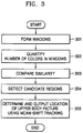
- FIG. 3 is a flowchart of the operation of the upper body candidate detector 103 shown in FIG. 1 .
- the upper body candidate detector 103 scatters several particles on a current frame picture provided by the first camera 101 and forms several windows around the scattered particles. If ten particles are scattered, ten windows are formed. The formed windows have the same size as the region 201.
- the upper body candidate detector 103 quantifies the number of colors in the windows using a color histogram of each of the windows.
- the upper body candidate detector 103 converts the quantified values of each of the windows into a Bhattacharyya coefficient and compares similarity between a tracking object window of a previous frame and each of the windows formed on the current frame picture.
- Information on the tracking object window of the previous frame is the quantified value on the upper body picture of the region 201 obtained by the upper body picture obtainer 102.
- the upper body candidate detector 103 gives more weights on a window quite similar to the tracking object window of the previous frame among the windows formed on the current frame picture than other windows, gathers particles on the window quite similar to the tracking object window, and detects candidate regions of the upper body picture of the current frame picture.
- the upper body candidate detector 103 uses a mean-shift tracking method for detecting a candidate region (or a particle) among the detected candidate regions.
- upper body candidate detector 103 takes the upper body picture obtained by the upper body picture obtainer 102 as a reference model, searches a candidate region closest and quite similar to the determined reference model among the detected candidate regions, determines the location of the searched candidate region as the location of the detected upper body candidate, and outputs the location information on the determined upper body candidate.
- the location information called a relative coordinate value is a two-dimensional coordinate value in the input picture provided by the first camera 101.
- the location information can be expressed as an orientation ⁇ of the upper body.
- the location information is provided to the tracking object selection module 130.
- the leg location detection module 110 includes a laser generator 111, a second camera 112, a leg picture obtainer 113, a picture distortion compensator 114, and a leg candidate detector 115 to detect at least one of leg location information for the human.
- the leg picture obtainer 113 controls the laser generator 111 and projects a laser beam horizontally when received the tracking start instruction from the user.
- the projected laser beam is referred to as structured light (SL).
- the laser may be an infrared laser beam.
- the second camera 112 uses a camera having an infrared filter when the laser generator 111 generates the infrared laser.
- the second camera 112 outputs a pickup picture of an SL laser line from the laser generator 111.
- the second camera 112 uses a fisheye lens for photographing a wider region.
- the leg picture obtainer 113 controls the laser generator 111 and obtains a leg picture from the pickup input picture from the second camera 112.
- the obtained leg picture is a projection frame picture identical to the output picture of the second camera 112.
- the leg picture obtainer 113 may obtain a predetermined specific region in the output picture of the second camera 112 as the leg picture.
- the picture distortion compensator 114 compensates for a distortion of the projection frame picture obtained by the leg picture obtainer 113.
- a distortion is a geometrical picture distortion caused by a lens (not shown) used in the second camera 112.
- the picture distortion compensator 114 compensates for both a radial distortion and a tangential distortion of the projection frame picture.
- the picture distortion compensator 114 outputs a projection picture whose distortion caused by the lens is compensated as shown in FIG. 4.
- FIG. 4 is an exemplary diagram of a leg picture compensated in the picture distortion compensator shown in FIG. 1 .
- the leg candidate detector 115 calculates a distance between pixels of a reflector based on an SL laser line included in the output projection picture of the picture distortion compensator 114.
- FIG. 5 illustrates the relationship between the laser generator 111, the second camera 112, and a projection plane formed by the structured light (SL) from the laser generator 111.
- XpYpZp denotes a frame of the laser generator 111
- XcYcZc denotes a frame of the second camera 112
- ⁇ denotes a rotation angle based on an X axis between the frames of the laser generator 111 and the second camera 112.
- Py denotes an offset distance toward a Y axis between the frames of the laser generator 111 and the second camera 112.
- the leg candidate detector 115 calculates a distance Zp between each of the SL laser lines included in the obtained leg picture and the mobile electronic system including the human tracking apparatus and a right and left distance Xp between the mobile electronic system and each of the SL laser lines.
- the leg candidate detector 115 maps the calculated distances Zp and XP two-dimensionally, thereby obtaining a two-dimensional picture including an SL laser line pattern as shown in FIG. 6 .
- FIG. 6 illustrates the two-dimensional picture including the SL laser line pattern corresponding to the projection frame picture shown in FIG. 4 .
- the leg candidate detector 115 detects leg candidates by grouping and clustering the two-dimensionally mapped picture according to the calculated distance between pixels.
- the leg candidate detector 115 obtains regions 611 and 612 in a region 610 by grouping and clustering the two-dimensionally mapped picture.
- the region 610 is an enlarged view of the two-dimensionally mapped picture.
- the leg candidate detector 115 detects leg candidates by calculating diagonal lengths I of the regions 611 and 612 and comparing the calculated diagonal lengths I with a characteristic value of a predetermined leg pattern size. Because the diagonal lengths I of grouped and clustered regions are similar to the characteristic value of the leg pattern size, the leg candidate detector 115 calculates the center position of the grouped and clustered regions and collects them as leg candidates.
- the leg pattern size is an attribute of an optimum leg pattern.
- the leg pattern size is determined based on leg pattern size of a plurality of adult males and females measured from 1 m and 3 m when the mobile electronic system sees a human's front, back, and side (right and left).
- a two-dimensional coordinate value (a relative coordinate value) of the leg candidate detected by the leg candidate detector 115 is transmitted to the tracking object selection module 130.
- the tracking object selection module 130 selects a tracking object using the two-dimensional coordinate values provided by the upper body candidate detector 103 and the leg candidate detector 115.
- the tracking object selection module 130 includes a tracking candidate detector 131 and a tracking object selector 132.
- the tracking candidate detector 131 detects leg candidates provided by the leg candidate detector 115 and the upper body candidate based on location information provided by the upper body candidate detector 103 as tracking candidates when selecting a tracking object in a first frame picture.
- the tracking candidate detector 131 determines a search range in which the location of the leg candidates selected as the tracking object at the first frame picture is a center coordinates in the second frame picture.
- FIGS. 7A and 7B are exemplary diagrams of search ranges based on the tracking object detected at the first frame picture.
- the search range is 703.
- the search range is determined based on an average stride and an average speed of adult male and female who walk forward and sideward, and a reaction speed of the mobile electronic system.
- the tracking candidate detector 131 detects every leg candidate included in the search range as tracking candidates.
- the tracking candidate detector 131 checks if the search range includes location information (or two-dimensional coordinate information) on the upper body candidate provided by the upper body candidate detector 103. If it is checked that the search range does not include the location information on the upper body candidate, the tracking candidate detector 131 disregards the location information on the upper body candidate in order to prevent an erroneous tracking caused by an erroneous detection of the location information of the upper body candidate.
- the tracking candidate detector 131 informs the user of a tracking object loss by calling the user or using other methods.
- the tracking candidate detector 131 informs the user of the tracking object loss.
- the tracking candidate detector 131 informs the user of a tracking object loss by calling the user or using other methods.
- the tracking candidate detector 131 outputs the location information of the tracking candidates to the tracking object selector 132.
- the tracking object selector 132 receives the location information of the upper body candidate and the leg candidates which are determined as the tracking candidates from the tracking candidate detector 131 and selects the optimum tracking object based on the received location information.
- FIG. 8 illustrates a process of selecting a tracking object in the tracking object selector 132 shown in FIG. 1 .
- the tracking object selector 132 receives location information on a plurality of leg candidates 802, 803, 804, and 805 and an upper body picture 811 included in a search range 800 based on a previous tracking object location 801, selects the leg candidate 804 closest to the upper body candidate 811 as a tracking object, selects the location of a leg pattern candidate closest to the previous tracking object location 801 as the tracking object, or selects the location of an upper body candidate as the tracking object when the location of the upper body candidate is closer to the previous tracking object location 801 than other leg pattern candidates.
- the tracking object selector 132 selects a location having the smallest displacement in the previous tracking object location 801 as the tracking object.
- the calculated orientation error and distance error are used to obtain the location relationship between each of leg candidates, an upper body candidate, and previous tracking objects within the search range.
- the tracking object selector 132 After the tracking object is selected, the tracking object selector 132 provides the location information of the selected tracking object to an obstacle register 140 and a tracking speed and orientation calculator 150.
- the obstacle register 140 compares the location information of the leg picture provided by the leg candidate detector 115 based on the SL laser line pattern with the location information of the tracking object provided by the tracking object selector 132.
- the location information of the leg picture based on the SL laser line pattern includes the location information of the SL laser line patterns that are detected and are not detected as a leg candidate by the leg candidate detector 115.
- the obstacle register 140 recognizes an SL laser line pattern having information on a location closest to the mobile electronic system among the detected location information having the SL laser line pattern as an obstacle to be avoided by the mobile electronic system.
- the obstacle register 140 selects the SL laser line pattern closest to the mobile electronic system as the obstacle and registers the location information of the selected obstacle.
- the location information having the SL laser line pattern that is selected as the obstacle may be the location information obtained by grouping and clustering the SL laser line pattern.
- FIG. 9 illustrates the relationship between a tracking speed and an obstacle avoidance speed.
- the tracking speed and orientation calculator 150 receives the location information of the tracking object from the tracking object selector 132 and the location information of the obstacle from the obstacle register 140 and determines final tracking orientation and speed of a mobile electronic system 901 using a vector sum of attraction between a human 900 and the mobile electronic system 901 and repulsion between an obstacle 902 and the mobile electronic system 901.
- FIG. 10 illustrates a process of determining right and left rotation speeds of a mobile electronic system in the tracking speed and orientation calculator 150 shown in FIG. 1 .
- the tracking speed and orientation calculator 150 determines a rotation speed of right and left wheels 1003 and 1004 of a mobile electronic system 1002 based on relative errors of the distance d and the orientation ⁇ between a selected tracking object 1001 and the mobile electronic system 1002, so that the mobile electronic system 1002 moves in a reverse direction of an obstacle location.
- a proportional integral derivative (PID) control algorithm can be used to determine the rotation speed of the right and left wheels 1003 and 1004.
- the motor controller 160 controls rotation orientation and speed of the motor 170 included in the mobile electronic system 1002 according to the calculated tracking speed and orientation.
- the motor 170 is used to rotate the right and left wheels 1003 and 1004 included in the mobile electronic system 1002.
- the tracking speed and orientation calculator 150, the motor controller 160, and the motor 170 are defined as am operating module for operating the human tracking apparatus used to track the selected tracking object.
- the human tracking apparatus calculates the tracking orientation at a fixed location and tracks the tracking object based on the calculated tracking orientation.
- FIG. 11 is a flowchart of a human tracking method according to an embodiment of the present invention.
- a mobile electronic system when a mobile electronic system receives a tracking start instruction by a user's voice or clap (operation 1101), it controls the first camera 101 and photographs the front of a predetermined distance.
- the mobile electronic system obtains an upper body picture of the user from the photographed picture (operation 1102) like in the upper body picture obtainer 102 shown in FIG. 1 . Therefore, the upper body picture can be obtained from the photographed picture regardless of a user's front, back, and side.
- the mobile electronic system detects an upper body candidate (or an upper body candidate picture) from a next frame picture based on the obtained upper body picture (operation 1103) using the particle filtering and the mean-shift tracking like in the upper body candidate detector 103 shown in FIG. 1 .
- the mobile electronic system detects the location information on the upper body candidate in an input picture using the upper body picture.
- the location information may be two-dimensional coordinate information.
- the mobile electronic system generates laser by controlling the laser generator 111 and obtains a projection picture including an SL laser line provided by the second camera 112 as a leg picture (operation 1104).
- the mobile electronic system compensates for a distortion of the obtained leg picture (operation 1105).
- the compensated picture distortion is a distortion caused by the lens included in the second camera 112.
- the mobile electronic system detects a leg candidate using an SL laser line pattern of the compensated leg picture like in the leg candidate detector 115 shown in FIG. 1 , and detects the location information of the detected leg candidate (operation 1106).
- the detected location information is two-dimensional coordinate information.
- the mobile electronic system detects tracking candidates using the location information of the upper body candidate detected in operation 1103 and the location information of the leg candidate detected in operation 1106 like in the tracking candidate detector 131 (operation 1107). If the location information of the upper body candidate is not detected in operation 1103, the location information of the leg candidate is not detected in operation 1106, or the detected location information of the upper body candidate and the leg candidate is not included in a search range determined based on a previous tracking object, the mobile electronic system can inform the user of a tracking object loss.
- the mobile electronic system selects tracking object among the detected tracking candidates (operation 1108) like in the tracking object selector 132 shown in FIG. 1 .
- the mobile electronic system registers an obstacle based on the location information of the selected tracking object and the location information based on the SL laser line pattern used to detect the leg candidates in operation 1106 (operation 1109).
- the mobile electronic system excludes the location information of the selected tracking object from the location information based on the SL laser line pattern and registers an SL laser line pattern having information on a location closest to the mobile electronic system as the obstacle.
- the location information based on the SL laser line pattern may be location information by grouping and clustering SL laser line pattern.
- the mobile electronic system calculates tracking speed and orientation based on the location information of the tracking object selected in operation 1108 and the location information of the obstacle registered in operation 1109 like in the tracking speed and orientation calculator 150 shown in FIG. 1 (operation 1110).
- the calculated tracking speed and orientation are used to control a motor (not shown) for controlling movement of the mobile electronic system (operation 1111). If the mobile electronics system receives a tracking end instruction from the user, it ends the upper body candidate tracking and the leg candidate tracking. However, if the mobile electronics system does not receive the tracking instruction from the user, operations 1102 and 1104 are performed.
- Computer-readable recording mediums include every kind of recording device that stores computer system-readable data. ROMs, RAMs, CD-ROMs, magnetic tapes, floppy discs, optical data storage, etc. are used as a computer-readable recording medium. Computer-readable recording mediums can also be realized in the form of a carrier wave (e.g., transmission through Internet). A computer-readable recording medium is dispersed in a network-connecting computer system, resulting in being stored and executed as a computer-readable code by a dispersion method.
- the mobile electronic system (robot) of the above-described embodiments does not require a user to carry a transmitting device in order to track the user. Since the mobile electronic system tracks an upper body picture based on a user's front, back, and side, it can track the user regardless of a user's position.
- a tracking object and an obstacle detection result are used to control tracking speed and orientation of the mobile electronic system, such that the mobile electronic system can avoid an obstacle while tracking. Also, the mobile electronic system can prevent an erroneous tracking using a tracking result of a user's upper body and legs.
Landscapes
- Engineering & Computer Science (AREA)
- Physics & Mathematics (AREA)
- Theoretical Computer Science (AREA)
- General Physics & Mathematics (AREA)
- Multimedia (AREA)
- Computer Vision & Pattern Recognition (AREA)
- Human Computer Interaction (AREA)
- Health & Medical Sciences (AREA)
- General Health & Medical Sciences (AREA)
- Psychiatry (AREA)
- Social Psychology (AREA)
- Databases & Information Systems (AREA)
- Mathematical Physics (AREA)
- Software Systems (AREA)
- General Engineering & Computer Science (AREA)
- Robotics (AREA)
- Mechanical Engineering (AREA)
- Data Mining & Analysis (AREA)
- Image Analysis (AREA)
- Control Of Position, Course, Altitude, Or Attitude Of Moving Bodies (AREA)
- Length Measuring Devices By Optical Means (AREA)
- Image Processing (AREA)
- Studio Devices (AREA)
- Manipulator (AREA)
- Steering Controls (AREA)
Applications Claiming Priority (1)
| Application Number | Priority Date | Filing Date | Title |
|---|---|---|---|
| KR1020040105650A KR100790860B1 (ko) | 2004-12-14 | 2004-12-14 | 사람 추적 장치 및 방법, 그 방법을 수행하기 위한프로그램이 저장된 기록매체와 그 장치를 포함하는 이동형전자기기 |
Publications (3)
| Publication Number | Publication Date |
|---|---|
| EP1672584A2 EP1672584A2 (en) | 2006-06-21 |
| EP1672584A3 EP1672584A3 (en) | 2009-07-15 |
| EP1672584B1 true EP1672584B1 (en) | 2016-04-27 |
Family
ID=35811646
Family Applications (1)
| Application Number | Title | Priority Date | Filing Date |
|---|---|---|---|
| EP05257657.6A Not-in-force EP1672584B1 (en) | 2004-12-14 | 2005-12-14 | Human tracking apparatus and method, storage medium storing program executing the method, and mobile electronic system including the apparatus |
Country Status (4)
| Country | Link |
|---|---|
| US (1) | US7330567B2 (ko) |
| EP (1) | EP1672584B1 (ko) |
| JP (1) | JP4815208B2 (ko) |
| KR (1) | KR100790860B1 (ko) |
Cited By (1)
| Publication number | Priority date | Publication date | Assignee | Title |
|---|---|---|---|---|
| TWI695180B (zh) * | 2018-07-24 | 2020-06-01 | 國立交通大學 | 機器人導引方法 |
Families Citing this family (34)
| Publication number | Priority date | Publication date | Assignee | Title |
|---|---|---|---|---|
| US7450735B1 (en) * | 2003-10-16 | 2008-11-11 | University Of Central Florida Research Foundation, Inc. | Tracking across multiple cameras with disjoint views |
| KR100647321B1 (ko) * | 2005-02-07 | 2006-11-23 | 삼성전자주식회사 | 사용자 위치 추적 방법 및 장치 |
| JP5558004B2 (ja) | 2006-01-13 | 2014-07-23 | ライカ・ゲオジステームス・アクチェンゲゼルシャフト | レーザートラッカーを用いたトラッキング方法及び測定システム |
| US8068935B2 (en) * | 2006-10-18 | 2011-11-29 | Yutaka Kanayama | Human-guided mapping method for mobile robot |
| KR101312625B1 (ko) * | 2006-11-03 | 2013-10-01 | 삼성전자주식회사 | 동작 추적 장치 및 방법 |
| JP5187878B2 (ja) * | 2007-01-31 | 2013-04-24 | 国立大学法人 東京大学 | 物体測定システム |
| US7974460B2 (en) * | 2007-02-06 | 2011-07-05 | Honeywell International Inc. | Method and system for three-dimensional obstacle mapping for navigation of autonomous vehicles |
| JP4315991B2 (ja) * | 2007-04-20 | 2009-08-19 | 本田技研工業株式会社 | 車両周辺監視装置、車両周辺監視方法、車両周辺監視プログラム |
| JP4631036B2 (ja) * | 2007-10-29 | 2011-02-16 | 東日本旅客鉄道株式会社 | 通行人行動解析装置及び通行人行動解析方法並びにそのプログラム |
| US8654197B2 (en) * | 2009-03-04 | 2014-02-18 | Raytheon Company | System and method for occupancy detection |
| JP2010237872A (ja) * | 2009-03-30 | 2010-10-21 | Sogo Keibi Hosho Co Ltd | 人物領域検出装置、人物領域検出方法、及び人物領域検出プログラム |
| JP5370009B2 (ja) * | 2009-08-31 | 2013-12-18 | 株式会社メガチップス | 監視システム |
| AU2009243528B2 (en) * | 2009-12-04 | 2013-08-01 | Canon Kabushiki Kaisha | Location-based signature selection for multi-camera object tracking |
| KR101014531B1 (ko) | 2009-12-30 | 2011-02-14 | 고려대학교 산학협력단 | 거리 센서를 이용한 다리 추출 방법, 이를 이용한 이동 로봇의 사람 추종 주행 방법 및 이동 로봇 |
| KR101054736B1 (ko) * | 2010-05-04 | 2011-08-05 | 성균관대학교산학협력단 | 3차원 물체 인식 및 자세 추정 방법 |
| KR101103923B1 (ko) * | 2010-10-20 | 2012-01-12 | 성균관대학교산학협력단 | 동영상을 촬영하는 카메라 로봇 및 카메라 로봇을 이용한 동영상 촬영 방법 |
| US8520080B2 (en) | 2011-01-31 | 2013-08-27 | Hand Held Products, Inc. | Apparatus, system, and method of use of imaging assembly on mobile terminal |
| US9321173B2 (en) | 2012-06-22 | 2016-04-26 | Microsoft Technology Licensing, Llc | Tracking and following people with a mobile robotic device |
| JP6003942B2 (ja) * | 2014-04-24 | 2016-10-05 | トヨタ自動車株式会社 | 動作制限装置及び動作制限方法 |
| KR101573620B1 (ko) | 2014-07-09 | 2015-12-02 | 고려대학교 산학협력단 | Sjpdaf기법을 기반으로 하는 다리 추종 방법 |
| US9943046B2 (en) | 2014-09-29 | 2018-04-17 | International Business Machines Corporation | Targeted irrigation using a central pivot irrigation system with a sensor network |
| CN105652895A (zh) * | 2014-11-12 | 2016-06-08 | 沈阳新松机器人自动化股份有限公司 | 基于激光传感器的移动机器人人体跟踪系统及跟踪方法 |
| US9623560B1 (en) * | 2014-11-26 | 2017-04-18 | Daniel Theobald | Methods of operating a mechanism and systems related therewith |
| US10044988B2 (en) * | 2015-05-19 | 2018-08-07 | Conduent Business Services, Llc | Multi-stage vehicle detection in side-by-side drive-thru configurations |
| FR3048406B1 (fr) * | 2016-03-07 | 2019-08-16 | Effidence | Robot autonome avec guidage en mode poussee |
| TW201805598A (zh) * | 2016-08-04 | 2018-02-16 | 鴻海精密工業股份有限公司 | 自主移動設備及建立導航路徑的方法 |
| KR101932200B1 (ko) * | 2016-11-07 | 2018-12-28 | 경일대학교산학협력단 | 이미지 인식을 이용한 보행자 보조 신호 제공 장치, 이를 위한 방법 및 이 방법을 수행하는 프로그램이 기록된 컴퓨터 판독 가능한 기록매체 |
| KR101907548B1 (ko) | 2016-12-23 | 2018-10-12 | 한국과학기술연구원 | 휴먼 추종을 위한 이동로봇의 주행 및 탐색방법 |
| KR102021833B1 (ko) * | 2017-09-26 | 2019-09-17 | 엘지전자 주식회사 | 인공지능을 이용한 이동 로봇 및 이동 로봇의 제어방법 |
| JP7318190B2 (ja) * | 2018-09-28 | 2023-08-01 | 株式会社ニコン | 形状測定装置、形状測定方法及び形状測定プログラム |
| JP7351083B2 (ja) * | 2018-12-28 | 2023-09-27 | 富士フイルムビジネスイノベーション株式会社 | 自律移動装置およびプログラム |
| FR3091609A1 (fr) | 2019-01-04 | 2020-07-10 | Balyo | Système de robot-compagnon comprenant un engin à guidage autonome |
| JP7192563B2 (ja) * | 2019-02-21 | 2022-12-20 | 新東工業株式会社 | 自律移動ロボット |
| CN114510021A (zh) * | 2021-12-15 | 2022-05-17 | 广东盈峰智能环卫科技有限公司 | 机器人自跟随方法和无人驾驶环卫机器人 |
Family Cites Families (15)
| Publication number | Priority date | Publication date | Assignee | Title |
|---|---|---|---|---|
| JP3062383B2 (ja) * | 1994-01-31 | 2000-07-10 | 沖電気工業株式会社 | 人物認識方法 |
| JPH0973543A (ja) * | 1995-09-06 | 1997-03-18 | Toshiba Corp | 画像処理装置 |
| JPH0990026A (ja) * | 1995-09-27 | 1997-04-04 | Honda Motor Co Ltd | 物体検出装置およびその方法 |
| JP3577875B2 (ja) * | 1997-03-06 | 2004-10-20 | 松下電器産業株式会社 | 移動物体抽出装置 |
| JPH1196376A (ja) * | 1997-09-24 | 1999-04-09 | Oki Electric Ind Co Ltd | 移動物体追跡装置及び方法 |
| US6795567B1 (en) * | 1999-09-16 | 2004-09-21 | Hewlett-Packard Development Company, L.P. | Method for efficiently tracking object models in video sequences via dynamic ordering of features |
| JP2001155164A (ja) * | 1999-11-26 | 2001-06-08 | Ntt Communications Kk | 移動物体追跡装置 |
| JP4531897B2 (ja) | 1999-12-27 | 2010-08-25 | パナソニック株式会社 | 人物追跡装置、人物追跡方法及びそのプログラムを記録した記録媒体 |
| US6629028B2 (en) * | 2000-06-29 | 2003-09-30 | Riken | Method and system of optical guidance of mobile body |
| JP3681620B2 (ja) * | 2000-07-26 | 2005-08-10 | 株式会社デンソー | 車両用障害物認識装置 |
| US20020100884A1 (en) * | 2001-01-29 | 2002-08-01 | Maddock Brian L.W. | Digital 3-D model production method and apparatus |
| JP3738694B2 (ja) * | 2001-02-28 | 2006-01-25 | 株式会社日本自動車部品総合研究所 | 可動型ケース |
| JP3416666B2 (ja) * | 2001-09-14 | 2003-06-16 | 三菱電機株式会社 | 頭部姿勢計測装置およびcgキャラクタ制御装置 |
| JP2003346159A (ja) | 2002-05-28 | 2003-12-05 | Oki Electric Ind Co Ltd | 人物追跡方法及び人物追跡装置 |
| KR20050063401A (ko) * | 2003-12-22 | 2005-06-28 | 한국전자통신연구원 | 인체 루트 위치 검출 방법 |
-
2004
- 2004-12-14 KR KR1020040105650A patent/KR100790860B1/ko not_active IP Right Cessation
-
2005
- 2005-10-04 US US11/241,968 patent/US7330567B2/en not_active Expired - Fee Related
- 2005-12-14 EP EP05257657.6A patent/EP1672584B1/en not_active Not-in-force
- 2005-12-14 JP JP2005359745A patent/JP4815208B2/ja not_active Expired - Fee Related
Cited By (1)
| Publication number | Priority date | Publication date | Assignee | Title |
|---|---|---|---|---|
| TWI695180B (zh) * | 2018-07-24 | 2020-06-01 | 國立交通大學 | 機器人導引方法 |
Also Published As
| Publication number | Publication date |
|---|---|
| KR100790860B1 (ko) | 2008-01-03 |
| US7330567B2 (en) | 2008-02-12 |
| EP1672584A2 (en) | 2006-06-21 |
| JP2006221610A (ja) | 2006-08-24 |
| KR20060066975A (ko) | 2006-06-19 |
| EP1672584A3 (en) | 2009-07-15 |
| JP4815208B2 (ja) | 2011-11-16 |
| US20060140450A1 (en) | 2006-06-29 |
Similar Documents
| Publication | Publication Date | Title |
|---|---|---|
| EP1672584B1 (en) | Human tracking apparatus and method, storage medium storing program executing the method, and mobile electronic system including the apparatus | |
| US7317474B2 (en) | Obstacle detection apparatus and method | |
| JP4871160B2 (ja) | ロボットおよびその制御方法 | |
| Ferryman et al. | Visual surveillance for moving vehicles | |
| US7321386B2 (en) | Robust stereo-driven video-based surveillance | |
| US7132933B2 (en) | Obstacle detection device and method therefor | |
| US7684894B2 (en) | Autonomously moving robot | |
| US6952488B2 (en) | System and method for object localization | |
| US7507948B2 (en) | Method of detecting object using structured light and robot using the same | |
| KR101618030B1 (ko) | 이동 로봇의 위치 인식 및 주행 제어 방법과 이를 이용한 이동 로봇 | |
| Nair et al. | Moving obstacle detection from a navigating robot | |
| JP2006252473A (ja) | 障害物検出装置、キャリブレーション装置、キャリブレーション方法およびキャリブレーションプログラム | |
| US20100215216A1 (en) | Localization system and method | |
| KR101456172B1 (ko) | 이동로봇의 위치인식 장치, 방법 및 이동로봇 | |
| JP2018155709A (ja) | 位置姿勢推定装置および位置姿勢推定方法、運転支援装置 | |
| US7286688B2 (en) | Object detection apparatus, distance measuring apparatus and object detection method | |
| JPH11257931A (ja) | 物体認識装置 | |
| JP2003281552A (ja) | 画像処理装置及びその方法 | |
| KR20200102108A (ko) | 차량의 객체 검출 장치 및 방법 | |
| CN115797405A (zh) | 一种基于车辆轴距的多镜头自适应跟踪方法 | |
| Ristić-Durrant et al. | Low-level sensor fusion-based human tracking for mobile robot | |
| KR101836847B1 (ko) | 이동 로봇 및 이동 로봇의 제어방법 | |
| JP2021026302A (ja) | 情報処理装置、情報処理方法及びプログラム | |
| Bonin-Font et al. | A visual navigation strategy based on inverse perspective transformation | |
| KR102688274B1 (ko) | 이동형 로봇 및 이동형 로봇의 충전 스테이션 도킹 방법 |
Legal Events
| Date | Code | Title | Description |
|---|---|---|---|
| PUAI | Public reference made under article 153(3) epc to a published international application that has entered the european phase |
Free format text: ORIGINAL CODE: 0009012 |
|
| AK | Designated contracting states |
Kind code of ref document: A2 Designated state(s): AT BE BG CH CY CZ DE DK EE ES FI FR GB GR HU IE IS IT LI LT LU LV MC NL PL PT RO SE SI SK TR |
|
| AX | Request for extension of the european patent |
Extension state: AL BA HR MK YU |
|
| PUAL | Search report despatched |
Free format text: ORIGINAL CODE: 0009013 |
|
| AK | Designated contracting states |
Kind code of ref document: A3 Designated state(s): AT BE BG CH CY CZ DE DK EE ES FI FR GB GR HU IE IS IT LI LT LU LV MC NL PL PT RO SE SI SK TR |
|
| AX | Request for extension of the european patent |
Extension state: AL BA HR MK YU |
|
| 17P | Request for examination filed |
Effective date: 20090902 |
|
| 17Q | First examination report despatched |
Effective date: 20091001 |
|
| AKX | Designation fees paid |
Designated state(s): DE FR GB |
|
| RAP1 | Party data changed (applicant data changed or rights of an application transferred) |
Owner name: SAMSUNG ELECTRONICS CO., LTD. |
|
| GRAJ | Information related to disapproval of communication of intention to grant by the applicant or resumption of examination proceedings by the epo deleted |
Free format text: ORIGINAL CODE: EPIDOSDIGR1 |
|
| GRAP | Despatch of communication of intention to grant a patent |
Free format text: ORIGINAL CODE: EPIDOSNIGR1 |
|
| INTG | Intention to grant announced |
Effective date: 20150803 |
|
| RIN1 | Information on inventor provided before grant (corrected) |
Inventor name: YOON, SANGMIN Inventor name: LEE, HYOUNGKI Inventor name: HONG, YOUNGJIN |
|
| INTG | Intention to grant announced |
Effective date: 20160126 |
|
| GRAS | Grant fee paid |
Free format text: ORIGINAL CODE: EPIDOSNIGR3 |
|
| GRAA | (expected) grant |
Free format text: ORIGINAL CODE: 0009210 |
|
| AK | Designated contracting states |
Kind code of ref document: B1 Designated state(s): DE FR GB |
|
| REG | Reference to a national code |
Ref country code: GB Ref legal event code: FG4D |
|
| REG | Reference to a national code |
Ref country code: DE Ref legal event code: R096 Ref document number: 602005049146 Country of ref document: DE |
|
| REG | Reference to a national code |
Ref country code: DE Ref legal event code: R097 Ref document number: 602005049146 Country of ref document: DE |
|
| PLBE | No opposition filed within time limit |
Free format text: ORIGINAL CODE: 0009261 |
|
| STAA | Information on the status of an ep patent application or granted ep patent |
Free format text: STATUS: NO OPPOSITION FILED WITHIN TIME LIMIT |
|
| 26N | No opposition filed |
Effective date: 20170130 |
|
| REG | Reference to a national code |
Ref country code: DE Ref legal event code: R119 Ref document number: 602005049146 Country of ref document: DE |
|
| GBPC | Gb: european patent ceased through non-payment of renewal fee |
Effective date: 20161214 |
|
| REG | Reference to a national code |
Ref country code: FR Ref legal event code: ST Effective date: 20170831 |
|
| PG25 | Lapsed in a contracting state [announced via postgrant information from national office to epo] |
Ref country code: FR Free format text: LAPSE BECAUSE OF NON-PAYMENT OF DUE FEES Effective date: 20170102 |
|
| PG25 | Lapsed in a contracting state [announced via postgrant information from national office to epo] |
Ref country code: DE Free format text: LAPSE BECAUSE OF NON-PAYMENT OF DUE FEES Effective date: 20170701 Ref country code: GB Free format text: LAPSE BECAUSE OF NON-PAYMENT OF DUE FEES Effective date: 20161214 |