EP1669721A1 - Timepiece with navigation aid for aviators and sailors - Google Patents
Timepiece with navigation aid for aviators and sailors Download PDFInfo
- Publication number
- EP1669721A1 EP1669721A1 EP04028918A EP04028918A EP1669721A1 EP 1669721 A1 EP1669721 A1 EP 1669721A1 EP 04028918 A EP04028918 A EP 04028918A EP 04028918 A EP04028918 A EP 04028918A EP 1669721 A1 EP1669721 A1 EP 1669721A1
- Authority
- EP
- European Patent Office
- Prior art keywords
- bezel
- timepiece according
- timepiece
- indications
- correction
- Prior art date
- Legal status (The legal status is an assumption and is not a legal conclusion. Google has not performed a legal analysis and makes no representation as to the accuracy of the status listed.)
- Withdrawn
Links
Images


Classifications
-
- G—PHYSICS
- G04—HOROLOGY
- G04B—MECHANICALLY-DRIVEN CLOCKS OR WATCHES; MECHANICAL PARTS OF CLOCKS OR WATCHES IN GENERAL; TIME PIECES USING THE POSITION OF THE SUN, MOON OR STARS
- G04B19/00—Indicating the time by visual means
- G04B19/28—Adjustable guide marks or pointers for indicating determined points of time
- G04B19/283—Adjustable guide marks or pointers for indicating determined points of time on rotatable rings, i.e. bezel
-
- G—PHYSICS
- G01—MEASURING; TESTING
- G01C—MEASURING DISTANCES, LEVELS OR BEARINGS; SURVEYING; NAVIGATION; GYROSCOPIC INSTRUMENTS; PHOTOGRAMMETRY OR VIDEOGRAMMETRY
- G01C21/00—Navigation; Navigational instruments not provided for in groups G01C1/00 - G01C19/00
- G01C21/20—Instruments for performing navigational calculations
-
- G—PHYSICS
- G04—HOROLOGY
- G04B—MECHANICALLY-DRIVEN CLOCKS OR WATCHES; MECHANICAL PARTS OF CLOCKS OR WATCHES IN GENERAL; TIME PIECES USING THE POSITION OF THE SUN, MOON OR STARS
- G04B47/00—Time-pieces combined with other articles which do not interfere with the running or the time-keeping of the time-piece
- G04B47/06—Time-pieces combined with other articles which do not interfere with the running or the time-keeping of the time-piece with attached measuring instruments, e.g. pedometer, barometer, thermometer or compass
- G04B47/061—Time-pieces combined with other articles which do not interfere with the running or the time-keeping of the time-piece with attached measuring instruments, e.g. pedometer, barometer, thermometer or compass calculating scales for indicating relationship between quantity and time
Definitions
- the present invention relates to a timepiece such as a wristwatch constituting an aid to navigation for airmen and sailors. More specifically, the present invention relates to such a timepiece allowing a pilot or a sailor to calculate the heading correction to bring to its trajectory to account for a crosswind.
- This navigation aid is in the form of an assembly of three concentric superimposed discs that can be rotated relative to each other and on which are reported information relating to the speed of the aircraft, true magnetic heading , the value of the crosswind and the angular correction to be made to the flight path of the aircraft.
- the airplane pilot as well as the navigator, therefore has an instrument which enables him, by means of a certain number of readings of numerical indications and calculations, to determine the course correction to be applied to take account of a crosswind. It is understandable, of course, that the pilot or the sailor must have this instrument at all times at hand. But this instrument can be easily misplaced among the many maps, official documents and others that the pilot or sailor must carry with him. On the other hand, this navigation instrument is conventionally made of cardboard. It can therefore get dirty and wear out.
- the present invention aims to overcome the aforementioned drawbacks as well as others by providing a timepiece which is associated with a navigational instrument of the abacus type as described above.
- the present invention relates to a timepiece, in particular of the wristwatch type, constituting an aid to navigation for airmen or navigators, characterized in that it comprises at least two concentric spectacles, one of which at least is rotating, one of those glasses wearing first indications corresponding to the speed of an airplane, respectively of a ship, and the other bearing indications relating to the correction of the heading to be applied in the event of crosswind, a chart for calculating the correction of heading being deferred on the back of the watch or on a separate card.
- the present invention provides a timepiece which is associated with a navigational instrument of the abacus type for aviators and navigators. As they constantly wear a watch on the wrist, they have immediately available an instrument allowing them to calculate the correction to be made to their trajectory to account for a possible crosswind. The risk of misplacing this instrument among other documents is avoided. Similarly, the invention provides an aid to navigation that is not likely to be dirty or deteriorated.
- the timepiece comprises a third rotating bezel on which are reported the results of the determination of the heading correction to be applied.
- the present invention will be described in connection with a wristwatch intended for use in the aviation industry. It goes without saying that the present invention applies in a similar way to the maritime world, the only difference being in the order of magnitude of the speeds involved, the speed of a ship being obviously much lower than that of a ship. aircraft.
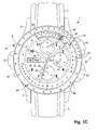
- the timepiece shown in connection with FIG. 1A is of the wristwatch type. It will be understood that the invention is not limited to such a wristwatch and that it can be applied to any type of timepiece such as a pocket watch.
- the wristwatch Designated as a whole by the general reference numeral 1, the wristwatch comprises a middle 2 extended at noon and six hours by two pairs of horns 4 for fixing the strands 6 of a bracelet.
- the wristwatch 1 also comprises a dial 8 above which a hand of the hours 10, a minute hand 12 and a seconds hand 14 move.
- Two wickets 16 and 18 are formed in the dial 8, respectively for the display of the day of the week and the date.
- dials 20, 22 and 24 are formed on the dial 8 of larger dimensions. These dials 20, 22 and 24 serve to count the seconds, minutes and hours when a timing function is activated and each comprise for this purpose a needle, respectively 26, 28 and 30.
- the wristwatch 1 also includes a ring 32 arranged at 9 o'clock for adjusting the watch functions.
- the wristwatch 1 further comprises two rings 34 and 36 arranged respectively at 2 o'clock and at 4 o'clock for the rotational control of two rotating spectacles 38 and 40 as described in detail below, as well as two pushers 42. and 44 at 8 o'clock and 10 o'clock for starting, stopping and resetting the chronograph function.
- the wristwatch 1 As can be seen from the examination of FIG. 1, the wristwatch 1 according to the invention is provided with three concentric rotary goggles 38, 40 and 46 on which are reported information relating to the speed of the aircraft and the course correction to apply.
- the rotating bezel 46 is an outer bezel that can be turned by hand.
- On this telescope 46 are reported 48 indications relating to the speed of the aircraft.
- the speeds reported on the telescope 46 correspond to one-tenth of the actual speed of the aircraft and are expressed in nautical miles per hour.
- the number "18" marked on the telescope 46 corresponds to a speed of the aircraft of 180Kts.
- the other two goggles 38 and 40 are internal rotating goggles which are rotated by crowns 34 and 36, respectively.
- graduations 50 expressed in degrees which correspond to the course correction to be applied to the trajectory of an aircraft according to a given crosswind.
- the telescope 38 also has a window 52 through which are visible graduations 54 carried on the telescope 40 which is arranged under the telescope 38.
- the graduations 54 reported on the telescope 40 correspond to the results of the calculations made by the airman to determine the course correction to be made to the trajectory of his aircraft taking into account the direction of the crosswind. Once its calculations are complete, the airman can make appear in the window 52 the result obtained by rotating the telescope 40 by means of the crown 36.
- the aviator thus has a function of memorizing the results of his calculations to which he can refer at any time.
- the graduations 54 carried on the telescope 40 correspond to directions expressed in degrees as will now be described in detail.
- VAR Magnetic declination
- the aviator has a marker 56, for example in the form of an arrow, materialized on the telescope 38 at the window 52.
- This marker gives the airman an indication of the direction of the wind. Indeed, we admit by default that the road to follow is at 12 o'clock. Therefore, it is very useful to always have in flight an indication of the direction of the wind in relation to the course to follow and to be able, at a glance, to determine if the wind is favorable or not. This is particularly important for calculating flight time or fuel consumption.
- the bezel 38 is rotatably provided to allow the user to temporarily memorize the difference between the true magnetic heading and the direction of the crosswind.
- the telescope 38 may be provided fixed, thus allowing to memorize only the final result of the calculations to which the aviator gave himself, namely the course to be followed by the pilot to account for the crosswind.
- the watch 1 comprises an outer bezel 46 and two inner goggles respectively upper 38 and lower 40.
- this example is given for illustrative purposes only and could also provide two outer rotating glasses 46a, 38a and a single inner rotating bezel 40a as shown schematically in Figure 3.
- an inner bezel means a bezel disposed under the window 60 of the watch 1
- an outer bezel means a window disposed around the window 60.
- Figures 4 and 5 are sectional views of the wristwatch 1 respectively along line IV-IV and line V-V of Figure 1.
- the ring 34 is mounted at the end of a rod 62 which is engaged in a through hole 64 formed at 2 o'clock in the middle part 2 of the watch 1.
- This rod 62 carries at its free end a pinion gear 66 for meshing with the teeth 68 provided at the base of the telescope 38.
- the ring 36 is mounted at the end of a rod 70 which is engaged in a through hole 72 formed at 4 hours in the middle 2 of the watch 1 and which carries at its free end a toothed pinion 74 intended to mesh with the teeth 76 provided at the base of the telescope 40.
- An elastic ring 78 disposed in a circular groove 80 made partly in the middle part 2 and partly in the outer bezel 46, is intended to allow said bezel 46 to rotate relative to said middle part 2 without hurting the latter.
- At least one and, preferably, two diametrically opposed blind holes 82 are also practiced in the middle 2.
- a spring 84 slightly compressed and surmounted by a ball 86 which is housed in a corresponding cavity 88 is provided at the base of the outer bezel 46. This device is a limitation to the rotation of the bezel 46 to prevent it from rotating too easily.
- a seal 90 is disposed between the lens 60 and the middle part 2 as well as seals 92 and 94 are arranged between each of the rotating spectacles 38 and 40 and said caseband 2.
- a seal 96 is also provided between the bottom 98 of the watch 1 and the caseband 2. The bottom 98 may for example be screwed to the middle part 2 by means of screws 100.
- screws 102 and 104 are provided for mounting the movement and its casing ring.
Landscapes
- Engineering & Computer Science (AREA)
- Radar, Positioning & Navigation (AREA)
- Remote Sensing (AREA)
- Physics & Mathematics (AREA)
- General Physics & Mathematics (AREA)
- Automation & Control Theory (AREA)
- Electric Clocks (AREA)
- Measurement Of Velocity Or Position Using Acoustic Or Ultrasonic Waves (AREA)
- Position Fixing By Use Of Radio Waves (AREA)
- Geophysics And Detection Of Objects (AREA)
- Credit Cards Or The Like (AREA)
- Instructional Devices (AREA)
Abstract
Description
La présente invention concerne une pièce d'horlogerie telle qu'une montre-bracelet constituant une aide à la navigation pour les aviateurs et les marins. Plus précisément, la présente invention concerne une telle pièce d'horlogerie permettant à un pilote ou à un marin de calculer la correction de cap à apporter à sa trajectoire pour tenir compte d'un vent de travers.The present invention relates to a timepiece such as a wristwatch constituting an aid to navigation for airmen and sailors. More specifically, the present invention relates to such a timepiece allowing a pilot or a sailor to calculate the heading correction to bring to its trajectory to account for a crosswind.
Supposons qu'un pilote d'avion veuille se rendre par la voie des airs d'un premier point à un second et que, sur la route que devra emprunter ce pilote pour relier ces deux points, souffle un vent de travers. Le pilote va devoir appliquer une correction à la trajectoire de son avion pour tenir compte du vent de travers, faute de quoi il dérivera de sa route et ne parviendra pas à relier son point de destination.Let us suppose that an airplane pilot wants to go by air from one point to another and that, on the road that this pilot will have to follow to connect these two points, a crosswind blows. The pilot will have to apply a correction to the trajectory of his aircraft to account for the crosswind, failing which he will drift off course and fail to connect his destination point.
Pour calculer cette correction de trajectoire, le pilote dispose actuellement d'un instrument du type abaque de navigation bien connu dans le mode aéronautique. Cette aide à la navigation se présente sous la forme d'un assemblage de trois disques concentriques superposés susceptibles d'être tournés les uns par rapport aux autres et sur lesquels sont reportées des informations relatives à la vitesse de l'avion, au cap magnétique vrai, à la valeur du vent de travers et à la correction angulaire à apporter à la trajectoire de l'avion. Sur le disque supérieur qui est transparent est reporté un abaque qui sert à effectuer une partie des calculs de correction de la trajectoire.To calculate this trajectory correction, the pilot currently has a navigation chart instrument well known in the aeronautical mode. This navigation aid is in the form of an assembly of three concentric superimposed discs that can be rotated relative to each other and on which are reported information relating to the speed of the aircraft, true magnetic heading , the value of the crosswind and the angular correction to be made to the flight path of the aircraft. On the upper disk, which is transparent, is an abacus that is used to perform part of the trajectory correction calculations.
Le pilote d'avion, de même que le navigateur, dispose donc d'un instrument qui lui permet, moyennant un certain nombre de lectures d'indications chiffrées et de calculs, de déterminer la correction du cap à appliquer pour tenir compte d'un vent de travers. On comprend, bien sûr, que le pilote ou le marin doit avoir en permanence cet instrument à portée de la main. Mais cet instrument peut être facilement égaré parmi les nombreuses cartes, documents officiels et autres que le pilote ou le marin doit emporter avec lui. D'autre part, cet instrument de navigation est classiquement réalisé en carton. Il peut donc se salir et s'user.The airplane pilot, as well as the navigator, therefore has an instrument which enables him, by means of a certain number of readings of numerical indications and calculations, to determine the course correction to be applied to take account of a crosswind. It is understandable, of course, that the pilot or the sailor must have this instrument at all times at hand. But this instrument can be easily misplaced among the many maps, official documents and others that the pilot or sailor must carry with him. On the other hand, this navigation instrument is conventionally made of cardboard. It can therefore get dirty and wear out.
La présente invention a pour but de remédier aux inconvénients susmentionnés ainsi qu'à d'autres encore en procurant une pièce d'horlogerie à laquelle est associé un instrument de navigation du type abaque tel que décrit ci-dessus.The present invention aims to overcome the aforementioned drawbacks as well as others by providing a timepiece which is associated with a navigational instrument of the abacus type as described above.
A cet effet, la présente invention concerne une pièce d'horlogerie, notamment du type montre-bracelet, constituant une aide à la navigation pour les aviateurs ou les navigateurs, caractérisée en ce qu'elle comprend au moins deux lunettes concentriques dont l'une au moins est tournante, l'une de ces lunettes portant des premières indications correspondant à la vitesse d'un avion, respectivement d'un bateau, et l'autre portant des indications relatives à la correction du cap à appliquer en cas de vent de travers, un abaque de calcul de la correction du cap étant reporté sur le dos de la montre ou sur une carte séparée.For this purpose, the present invention relates to a timepiece, in particular of the wristwatch type, constituting an aid to navigation for airmen or navigators, characterized in that it comprises at least two concentric spectacles, one of which at least is rotating, one of those glasses wearing first indications corresponding to the speed of an airplane, respectively of a ship, and the other bearing indications relating to the correction of the heading to be applied in the event of crosswind, a chart for calculating the correction of heading being deferred on the back of the watch or on a separate card.
Grâce à ces caractéristiques, la présente invention procure une pièce d'horlogerie à laquelle est associé un instrument de navigation du type abaque pour aviateurs et navigateurs. Comme ces derniers portent en permanence une montre au poignet, ils ont ainsi immédiatement à disposition un instrument leur permettant de calculer la correction à apporter à leur trajectoire pour tenir compte d'un éventuel vent de travers. Le risque d'égarer cet instrument parmi d'autres documents est évité. De même, l'invention procure une aide à la navigation qui ne risque pas d'être salie ou détériorée.Thanks to these features, the present invention provides a timepiece which is associated with a navigational instrument of the abacus type for aviators and navigators. As they constantly wear a watch on the wrist, they have immediately available an instrument allowing them to calculate the correction to be made to their trajectory to account for a possible crosswind. The risk of misplacing this instrument among other documents is avoided. Similarly, the invention provides an aid to navigation that is not likely to be dirty or deteriorated.
Selon une caractéristique complémentaire de l'invention, la pièce d'horlogerie comprend une troisième lunette tournante sur laquelle sont reportés les résultats de la détermination de la correction de cap à appliquer.According to a complementary feature of the invention, the timepiece comprises a third rotating bezel on which are reported the results of the determination of the heading correction to be applied.
L'utilisateur dispose ainsi d'un aide-mémoire qui lui permet de se rappeler des calculs qu'il a effectués et qui lui évite de devoir éventuellement refaire ces calculs qui sont relativement longs et complexes.The user thus has an aide-memoire which allows him to remember the calculations he has made and which avoids the need to repeat these calculations that are relatively long and complex.
D'autres caractéristiques et avantages de la présente invention ressortiront plus clairement de la description détaillée qui suit d'un mode de réalisation de la pièce d'horlogerie selon l'invention, cet exemple étant donné à titre purement illustratif et non limitatif seulement en liaison avec le dessin annexé sur lequel :
- les figures 1A à 1C sont des vues de dessus d'une montre-bracelet conforme à la présente invention à différents stades des calculs de correction de la trajectoire;
- la figure 2 est une représentation d'un abaque utile à la détermination de la correction de cap à appliquer à la trajectoire d'un aéronef ou d'une embarcation et qui peut être reporté sur le dos de la montre ou sur une carte séparée;
- la figure 3 est une représentation schématique d'une variante de réalisation de la montre représentée à la figure 1;
- la figure 4 est une vue en coupe selon la ligne IV-IV de la figure 1, et
- la figure 5 est une vue en coupe selon la ligne V-V de la figure 1.
- FIGS. 1A to 1C are top views of a wristwatch according to the present invention at different stages of the trajectory correction calculations;
- FIG. 2 is a representation of an abacus useful for determining the course correction to be applied to the trajectory of an aircraft or craft and which can be carried on the back of the watch or on a separate chart;
- Figure 3 is a schematic representation of an alternative embodiment of the watch shown in Figure 1;
- FIG. 4 is a sectional view along the line IV-IV of FIG. 1, and
- Figure 5 is a sectional view along the line VV of Figure 1.
La présente invention va être décrite en liaison avec une montre-bracelet destinée à être utilisée dans le milieu aéronautique. Il va de soi que la présente invention s'applique de manière analogue au monde maritime, la seule différence résidant dans l'ordre de grandeur des vitesses mises en jeu, la vitesse d'un navire étant bien évidemment bien inférieure à celle d'un aéronef.The present invention will be described in connection with a wristwatch intended for use in the aviation industry. It goes without saying that the present invention applies in a similar way to the maritime world, the only difference being in the order of magnitude of the speeds involved, the speed of a ship being obviously much lower than that of a ship. aircraft.
La pièce d'horlogerie représentée en liaison avec la figure 1A est du type montre-bracelet. On comprendra que l'invention n'est pas limitée à une telle montre-bracelet et qu'elle peut s'appliquer à tout type de pièce d'horlogerie telle qu'une montre de poche. Désignée dans son ensemble par la référence numérique générale 1, la montre-bracelet comprend une carrure 2 prolongée à midi et à six heures par deux paires de cornes 4 pour la fixation des brins 6 d'un bracelet.The timepiece shown in connection with FIG. 1A is of the wristwatch type. It will be understood that the invention is not limited to such a wristwatch and that it can be applied to any type of timepiece such as a pocket watch. Designated as a whole by the
La montre-bracelet 1 comprend par ailleurs un cadran 8 au-dessus duquel se déplacent une aiguille des heures 10, une aiguille des minutes 12 et une aiguille des secondes 14. Deux guichets 16 et 18 sont pratiqués dans le cadran 8, respectivement pour l'affichage du jour de la semaine et du quantième.The
Trois autres petits cadrans 20, 22 et 24 sont ménagés sur le cadran 8 de dimensions plus grandes. Ces cadrans 20, 22 et 24 servent au comptage des secondes, des minutes et des heures lorsqu'une fonction de chronométrage est activée et comprennent chacun à cet effet une aiguille, respectivement 26, 28 et 30.Three other
La montre-bracelet 1 comprend également une couronne 32 disposée à 9 heures pour le réglage des fonctions horlogères. La montre-bracelet 1 comprend d'autre part deux couronnes 34 et 36 disposées respectivement à 2 heures et à 4 heures pour la commande en rotation de deux lunettes rotatives 38 et 40 comme décrit en détail ci-dessous, de même que deux poussoirs 42 et 44 disposés à 8 heures et à 10 heures pour le démarrage, l'arrêt et la remise à zéro de la fonction chronographe.The
Comme on peut le voir à l'examen de la figure 1, la montre-bracelet 1 selon l'invention est pourvue de trois lunettes rotatives concentriques 38, 40 et 46 sur lesquelles sont reportées des informations relatives à la vitesse de l'avion et à la correction de cap à appliquer.As can be seen from the examination of FIG. 1, the
Plus précisément, la lunette rotative 46 est une lunette extérieure susceptible d'être tournée à la main. Sur cette lunette 46 sont reportées des indications 48 relatives à la vitesse de l'avion. Les vitesses reportées sur la lunette 46 correspondent au dixième de la vitesse réelle de l'avion et sont exprimées en miles nautiques par heure. Ainsi, au nombre "18" marqué sur la lunette 46 correspond une vitesse de l'avion de 180Kts.More specifically, the
Les deux autres lunettes 38 et 40 sont des lunettes rotatives intérieures qui sont commandées en rotation par les couronnes 34 et 36 respectivement. Sur la lunette 38 sont reportées des graduations 50 exprimées en degrés qui correspondent à la correction de cap à appliquer à la trajectoire d'un avion en fonction d'un vent de travers donné. La lunette 38 présente par ailleurs un guichet 52 à travers lequel sont visibles des graduations 54 reportées sur la lunette 40 qui est disposée sous la lunette 38. Les graduations 54 reportées sur la lunette 40 correspondent aux résultats des calculs effectués par l'aviateur pour déterminer la correction de cap à apporter à la trajectoire de son avion compte tenu de la direction du vent de travers. Une fois ses calculs achevés, l'aviateur peut faire apparaître dans le guichet 52 le résultat obtenu en faisant tourner la lunette 40 au moyen de la couronne 36. L'aviateur dispose ainsi d'une fonction de mémorisation des résultats de ses calculs à laquelle il peut se référer à tout moment. Les graduations 54 reportées sur la lunette 40 correspondent à des directions exprimées en degrés comme il va maintenant être décrit en détail.The other two
L'utilisateur doit tout d'abord déterminer au moyen d'une carte géographique la déclinaison magnétique appelée "VAR" à l'endroit où il se trouve. La déclinaison magnétique (VAR) est l'écart entre le nord géographique correspondant à l'orientation des méridiens tracés sur la carte et le nord magnétique indiqué par le compas ou boussole. A titre d'exemple, la déclinaison magnétique est de 4° ouest dans l'ouest de la France et de 1 ° ouest à Genève (Suisse). Si le cap à suivre est par exemple de 140° et que la déclinaison magnétique est de 10° ouest, il faut soustraire la déclinaison magnétique de ce cap, c'est-à-dire le cap 140° - 10° = 130°. Il faut ensuite connaître la force et la direction du vent sur le trajet. Ces informations sont données par la tour de contrôle pour les phases de décollage et d'atterrissage, et par les cartes aériennes pour les vents en altitude. Supposons donc que le vent souffle à 40Kts et que sa direction soit de 100°. On calcule alors la différence entre le cap à suivre (130°) et la direction du vent (100°) et l'on obtient un résultat égal à 130° - 100° = 30°. Le zéro de la graduation 54 reportée sur la lunette 40 étant placé à 12 heures, on fait alors tourner la lunette 38 au moyen de la couronne 34 de façon à faire apparaître dans le guichet 52 le nombre "30" correspondant au résultat du calcul effectué de la manière décrite ci-dessus (voir figure 1 B). L'aviateur peut ainsi temporairement mémoriser ce résultat intermédiaire. En outre, l'aviateur dispose d'un repère 56, par exemple sous la forme d'une flèche, matérialisé sur la lunette 38 au niveau du guichet 52. Ce repère donne à l'aviateur une indication quant à la direction du vent. En effet, on admet par défaut que la route à suivre est à 12h. Dès lors, il est très utile de toujours avoir en vol une indication de la direction du vent par rapport au cap à suivre et de pouvoir ainsi, d'un simple coup d'oeil, déterminer si le vent est favorable ou non. Ceci est particulièrement important pour le calcul du temps de vol ou de la consommation en carburant.The user must first determine by means of a map the magnetic declination called "VAR" at the place where it is located. Magnetic declination (VAR) is the difference between the geographic north corresponding to the orientation of the meridians drawn on the map and the magnetic north indicated by the compass or compass. For example, the magnetic declination is 4 ° West in western France and 1 ° West in Geneva (Switzerland). If the course to be followed is for example 140 ° and the magnetic declination is 10 ° west, subtract the magnetic declination of this heading, that is to say, heading 140 ° - 10 ° = 130 °. It is then necessary to know the force and the direction of the wind on the way. This information is given by the control tower for the take-off and landing phases, and by the aerial charts for upper winds. Suppose, then, that the wind blows at 40Kts and that its direction is 100 °. The difference between the course to follow (130 °) and the direction of the wind (100 °) is then calculated and a result equal to 130 ° - 100 ° = 30 ° is obtained. The zero of the
Supposons maintenant que la vitesse réelle de l'avion soit de 180Kts. L'utilisateur va tourner à la main la lunette rotative extérieure 46 pour amener le nombre "18" en regard du repère 56. Il faut ensuite se reporter à l'abaque 58 (voir figure 2) qui peut être prévu sur le dos de la montre ou sur une carte séparée. Sur l'arc de cercle le plus extérieur figurent les composantes du vent de travers. On soustrait la valeur de 30° calculée précédemment de la valeur 90° et on obtient 60°. On décompose ce point dans un repère des vitesses orthonormé. La projection de ce point sur l'axe des abscisses donne une valeur de 25Kts et la projection du même point sur l'axe des ordonnées donne une valeur de 44Kts. On additionne la vitesse de l'avion au chiffre précédent soit 180 + 25 = 205Kts. Sur la lunette 46 on lit la valeur 205Kts qui correspond à peu de chose près au chiffre "20" lorsque cette valeur est rapportée au dixième, et on lit le chiffre correspondant en regard sur la lunette 38, soit environ 6,5°. On additionne cette composante de vent de travers de 6,5° à la valeur du cap magnétique vrai égale à 130° et on obtient ainsi un cap réel de 136,5° qui correspond au cap à suivre par le pilote en tenant compte du vent de travers. Pour mémoire, on peut faire apparaître le résultat de ce calcul (136,5°) dans le guichet 52 en faisant tourner la lunette 40 au moyen de la couronne 36. L'utilisateur dispose ainsi d'un aide-mémoire qui lui permet de se rappeler du résultat définitif des calculs auxquels il a procédé (voir figure 1 C).Suppose now that the actual speed of the aircraft is 180Kts. The user will manually turn the outer
Dans tout ce qui vient d'être décrit jusqu'à présent, la lunette 38 est prévue rotative, ceci pour permettre à l'utilisateur de mémoriser temporairement la différence entre le cap magnétique vrai et la direction du vent de travers. Cependant, selon une variante d'exécution simplifiée de l'invention, la lunette 38 pourra être prévue fixe, ne permettant donc de mémoriser que le résultat final des calculs auxquels s'est livré l'aviateur, à savoir le cap à suivre par le pilote pour tenir compte du vent de travers.In all that has been described so far, the
Dans l'exemple illustré aux figures 1A à 1C, la montre 1 selon l'invention comprend une lunette extérieure 46 et deux lunettes intérieures respectivement supérieure 38 et inférieure 40. Bien entendu, cet exemple est donné à titre purement illustratif seulement et l'on pourrait également prévoir deux lunettes rotatives extérieures 46a, 38a et une seule lunette rotative intérieure 40a comme représenté schématiquement à la figure 3.In the example illustrated in FIGS. 1A to 1C, the
On comprendra que l'on entend par lunette intérieure une lunette disposée sous la glace 60 de la montre 1, tandis que l'on désigne par lunette extérieure une lunette disposée autour de la glace 60.It will be understood that an inner bezel means a bezel disposed under the
Les figures 4 et 5 sont des vues en coupe de la montre-bracelet 1 respectivement selon la ligne IV-IV et la ligne V-V de la figure 1.Figures 4 and 5 are sectional views of the
La couronne 34 est montée à l'extrémité d'une tige 62 qui est engagée dans un trou traversant 64 ménagé à 2 heures dans la carrure 2 de la montre 1. Cette tige 62 porte à son extrémité libre un pignon denté 66 destiné à engrener avec les dents 68 prévues à la base de la lunette 38. De même, la couronne 36 est montée à l'extrémité d'une tige 70 qui est engagée dans un trou traversant 72 ménagé à 4 heures dans la carrure 2 de la montre 1 et qui porte à son extrémité libre une pignon denté 74 destiné à engrener avec les dents 76 prévues à la base de la lunette 40.The
Une bague élastique 78, disposée dans une gorge circulaire 80 pratiquée pour partie dans la carrure 2 et pour partie dans la lunette extérieure 46, est destinée à permettre à ladite lunette 46 de tourner relativement à ladite carrure 2 sans blesser cette dernière. On pratique également au moins un et, préférentiellement, deux trous borgnes 82 diamétralement opposés dans la carrure 2. Dans chacun de ces trous borgnes 82 est disposé un ressort 84 légèrement comprimé et surmonté d'une bille 86 qui vient se loger dans une cavité correspondante 88 prévue à la base de la lunette extérieure 46. Ce dispositif constitue une limitation à la rotation de la lunette 46 pour empêcher celle-ci de tourner trop facilement. Un joint d'étanchéité 90 est disposé entre la glace 60 et la carrure 2 de même que des joints 92 et 94 sont disposés entre chacune des lunettes rotatives 38 et 40 et ladite carrure 2. Un joint 96 est également prévu entre le fond 98 de la montre 1 et la carrure 2. Le fond 98 peut par exemple être vissé sur la carrure 2 au moyen de vis 100. Enfin, des vis 102 et 104 sont prévues pour le montage du mouvement et de son cercle d'encageage.An
Il va de soi que la présente invention n'est pas limitée au mode de réalisation qui vient d'être décrit et que diverses modifications et variantes simples peuvent être envisagées par l'homme du métier sans sortir du cadre de la présente invention tel que défini par les revendications annexées à la présente demande de brevet.It goes without saying that the present invention is not limited to the embodiment which has just been described and that various modifications and simple variants can be envisaged by those skilled in the art without departing from the scope of the present invention as defined by the claims appended to this patent application.
Claims (9)
Priority Applications (6)
| Application Number | Priority Date | Filing Date | Title |
|---|---|---|---|
| EP04028918A EP1669721A1 (en) | 2004-12-07 | 2004-12-07 | Timepiece with navigation aid for aviators and sailors |
| EP05806463A EP1825219B1 (en) | 2004-12-07 | 2005-11-08 | Timepiece with navigation aid for aviators and sailors |
| AT05806463T ATE469337T1 (en) | 2004-12-07 | 2005-11-08 | WATCH WITH A NAVIGATION AID FOR aviators and sailors |
| DE602005021542T DE602005021542D1 (en) | 2004-12-07 | 2005-11-08 | CLOCK WITH A NAVIGATION HELP FOR FLYERS AND SEA-DRIVERS |
| US11/721,134 US7782714B2 (en) | 2004-12-07 | 2005-11-08 | Time piece forming a navigation aid for pilots and seamen |
| PCT/EP2005/011941 WO2006061072A1 (en) | 2004-12-07 | 2005-11-08 | Time piece forming a navigation aid for pilots and seamen |
Applications Claiming Priority (1)
| Application Number | Priority Date | Filing Date | Title |
|---|---|---|---|
| EP04028918A EP1669721A1 (en) | 2004-12-07 | 2004-12-07 | Timepiece with navigation aid for aviators and sailors |
Publications (1)
| Publication Number | Publication Date |
|---|---|
| EP1669721A1 true EP1669721A1 (en) | 2006-06-14 |
Family
ID=34927672
Family Applications (2)
| Application Number | Title | Priority Date | Filing Date |
|---|---|---|---|
| EP04028918A Withdrawn EP1669721A1 (en) | 2004-12-07 | 2004-12-07 | Timepiece with navigation aid for aviators and sailors |
| EP05806463A Active EP1825219B1 (en) | 2004-12-07 | 2005-11-08 | Timepiece with navigation aid for aviators and sailors |
Family Applications After (1)
| Application Number | Title | Priority Date | Filing Date |
|---|---|---|---|
| EP05806463A Active EP1825219B1 (en) | 2004-12-07 | 2005-11-08 | Timepiece with navigation aid for aviators and sailors |
Country Status (5)
| Country | Link |
|---|---|
| US (1) | US7782714B2 (en) |
| EP (2) | EP1669721A1 (en) |
| AT (1) | ATE469337T1 (en) |
| DE (1) | DE602005021542D1 (en) |
| WO (1) | WO2006061072A1 (en) |
Cited By (2)
| Publication number | Priority date | Publication date | Assignee | Title |
|---|---|---|---|---|
| ITPN20080063A1 (en) * | 2008-07-23 | 2008-10-23 | Valerio Pontarolo | GONIOMETRIC RULES OF MOVEMENTS SUPPORTING SAILING SAILING |
| WO2009037189A1 (en) * | 2007-09-21 | 2009-03-26 | Senses Ltd. | Timepiece with mach number indicator |
Families Citing this family (5)
| Publication number | Priority date | Publication date | Assignee | Title |
|---|---|---|---|---|
| JP5502705B2 (en) * | 2010-11-17 | 2014-05-28 | セイコーインスツル株式会社 | clock |
| US20140269218A1 (en) * | 2013-03-15 | 2014-09-18 | Jeffrey Herold | Watch Engaged ATIS Reminder Systems |
| JP1521972S (en) * | 2014-04-28 | 2015-04-20 | ||
| JP6903956B2 (en) * | 2017-03-07 | 2021-07-14 | セイコーエプソン株式会社 | Electronic clock |
| USD965445S1 (en) | 2022-04-22 | 2022-10-04 | Eshaan Kothari | Abacus watch |
Citations (4)
| Publication number | Priority date | Publication date | Assignee | Title |
|---|---|---|---|---|
| CH192393A (en) * | 1936-11-12 | 1937-08-15 | Rodolphe Forrer Alfred | Flight kit for air navigation. |
| GB555155A (en) * | 1942-02-04 | 1943-08-06 | Reece Buttonhole Machine Compa | Combined timepiece and ground speed and distance indicator |
| JPH02236488A (en) * | 1989-03-10 | 1990-09-19 | Seiko Epson Corp | Timepiece with navigational calculating device |
| FR2652156A1 (en) * | 1989-09-19 | 1991-03-22 | Horlogerie Franc | Device for manual determination of length/time |
Family Cites Families (11)
| Publication number | Priority date | Publication date | Assignee | Title |
|---|---|---|---|---|
| US3127102A (en) * | 1964-03-31 | Flight navigation instrument | ||
| US2775404A (en) * | 1954-08-12 | 1956-12-25 | United Air Lines Inc | Navigational computers |
| US3203391A (en) * | 1963-09-09 | 1965-08-31 | Lloyd E Corwin | Air navigation instrument |
| US3241308A (en) * | 1964-08-14 | 1966-03-22 | Bill E Forney | Flight watch adapter |
| US3835299A (en) * | 1973-09-21 | 1974-09-10 | P Turney | Navigational computers |
| US3971915A (en) * | 1974-12-11 | 1976-07-27 | Nasa | Sun angle calculator |
| US4359629A (en) * | 1980-07-08 | 1982-11-16 | J & K Shepard Pty. Limited | Tactical indicator for bulkhead and other compasses |
| GB2128378B (en) * | 1982-08-24 | 1986-01-02 | Citizen Watch Co Ltd | Water-resisting structure for a watch |
| FR2628202B1 (en) * | 1988-03-01 | 1993-04-02 | Poirier Alain | DEVICE FOR DIRECT READING, ON A CARD, OF THE COURSE TO BE FOLLOWED BY AN AERIAL OR NAUTICAL VEHICLE |
| US5982710A (en) * | 1997-03-14 | 1999-11-09 | Rawat; Prem P. | Method and apparatus for providing time using cartesian coordinates |
| CH691089A5 (en) * | 1997-05-14 | 2001-04-12 | Asulab Sa | timepiece associated with a compass and a viewfinder. |
-
2004
- 2004-12-07 EP EP04028918A patent/EP1669721A1/en not_active Withdrawn
-
2005
- 2005-11-08 DE DE602005021542T patent/DE602005021542D1/en active Active
- 2005-11-08 EP EP05806463A patent/EP1825219B1/en active Active
- 2005-11-08 WO PCT/EP2005/011941 patent/WO2006061072A1/en active Application Filing
- 2005-11-08 US US11/721,134 patent/US7782714B2/en active Active
- 2005-11-08 AT AT05806463T patent/ATE469337T1/en not_active IP Right Cessation
Patent Citations (4)
| Publication number | Priority date | Publication date | Assignee | Title |
|---|---|---|---|---|
| CH192393A (en) * | 1936-11-12 | 1937-08-15 | Rodolphe Forrer Alfred | Flight kit for air navigation. |
| GB555155A (en) * | 1942-02-04 | 1943-08-06 | Reece Buttonhole Machine Compa | Combined timepiece and ground speed and distance indicator |
| JPH02236488A (en) * | 1989-03-10 | 1990-09-19 | Seiko Epson Corp | Timepiece with navigational calculating device |
| FR2652156A1 (en) * | 1989-09-19 | 1991-03-22 | Horlogerie Franc | Device for manual determination of length/time |
Non-Patent Citations (1)
| Title |
|---|
| PATENT ABSTRACTS OF JAPAN vol. 014, no. 554 (P - 1140) 10 December 1990 (1990-12-10) * |
Cited By (4)
| Publication number | Priority date | Publication date | Assignee | Title |
|---|---|---|---|---|
| WO2009037189A1 (en) * | 2007-09-21 | 2009-03-26 | Senses Ltd. | Timepiece with mach number indicator |
| WO2009036808A1 (en) * | 2007-09-21 | 2009-03-26 | Senses Ltd. | Timepiece with true airspeed indicator |
| ITPN20080063A1 (en) * | 2008-07-23 | 2008-10-23 | Valerio Pontarolo | GONIOMETRIC RULES OF MOVEMENTS SUPPORTING SAILING SAILING |
| WO2010010445A1 (en) * | 2008-07-23 | 2010-01-28 | Pontarolo Engineering S.P.A. | Goniometric rule for defining points of sail as an aid to sailing |
Also Published As
| Publication number | Publication date |
|---|---|
| US7782714B2 (en) | 2010-08-24 |
| US20090231961A1 (en) | 2009-09-17 |
| ATE469337T1 (en) | 2010-06-15 |
| WO2006061072A1 (en) | 2006-06-15 |
| EP1825219A1 (en) | 2007-08-29 |
| DE602005021542D1 (en) | 2010-07-08 |
| EP1825219B1 (en) | 2010-05-26 |
Similar Documents
| Publication | Publication Date | Title |
|---|---|---|
| EP1825219B1 (en) | Timepiece with navigation aid for aviators and sailors | |
| EP2544055B1 (en) | Display of a physical magnitude on a clock display medium | |
| EP0663631B1 (en) | Timepiece displaying the part of earth visible from the moon | |
| EP0694822B1 (en) | Watch with a magnetic, north, indicating device | |
| EP1498790B1 (en) | Astronomical watch | |
| EP1483630B1 (en) | Watch comprising a solar time display | |
| EP1095318B1 (en) | Watch equipped with means for determining a location longitude | |
| EP2009392B1 (en) | Orientation watch | |
| EP3211487A1 (en) | Device for a mechanism for calculating astronomical phenomena | |
| EP3696617B1 (en) | Mechanism for displaying month and leap year for a timepiece | |
| EP1866708B1 (en) | Timepiece | |
| CH680631B5 (en) | ||
| FR2652156A1 (en) | Device for manual determination of length/time | |
| JP4539971B2 (en) | Moon clock | |
| CH715167B1 (en) | Astronomical display device. | |
| EP4055448A2 (en) | Device for displaying the moon on demand | |
| EP1235120B1 (en) | Analogical timepiece with a time indication based on a decimal system | |
| EP3792703A1 (en) | Rotary needle around two axes | |
| CH717029B1 (en) | Mechanism for displaying the time in a predefined time zone for a watch movement. | |
| CH710874A2 (en) | A display device of the orbital position of the moon for a timepiece and a timepiece. | |
| EP0961182A1 (en) | Tide indicating timepiece | |
| CH672867B5 (en) | ||
| BE388433A (en) | ||
| FR2796169A1 (en) | Procedure for determination of times of high and low tides over a limited period, such as a week, by application of a sticky label to a watch face with appropriate day markings on the label so that the high and low tides are shown | |
| CH693518A5 (en) | Procedure for determination of times of high and low tides over a limited period, such as a week, by application of a sticky label to a watch face with appropriate day markings on the label so that the high and low tides are shown |
Legal Events
| Date | Code | Title | Description |
|---|---|---|---|
| PUAI | Public reference made under article 153(3) epc to a published international application that has entered the european phase |
Free format text: ORIGINAL CODE: 0009012 |
|
| AK | Designated contracting states |
Kind code of ref document: A1 Designated state(s): AT BE BG CH CY CZ DE DK EE ES FI FR GB GR HU IE IS IT LI LT LU MC NL PL PT RO SE SI SK TR |
|
| AX | Request for extension of the european patent |
Extension state: AL BA HR LV MK YU |
|
| AKX | Designation fees paid | ||
| REG | Reference to a national code |
Ref country code: DE Ref legal event code: 8566 |
|
| STAA | Information on the status of an ep patent application or granted ep patent |
Free format text: STATUS: THE APPLICATION IS DEEMED TO BE WITHDRAWN |
|
| 18D | Application deemed to be withdrawn |
Effective date: 20061215 |