EP1669643A1 - Motorgetriebene getriebebetätigungseinheit - Google Patents
Motorgetriebene getriebebetätigungseinheit Download PDFInfo
- Publication number
- EP1669643A1 EP1669643A1 EP04705153A EP04705153A EP1669643A1 EP 1669643 A1 EP1669643 A1 EP 1669643A1 EP 04705153 A EP04705153 A EP 04705153A EP 04705153 A EP04705153 A EP 04705153A EP 1669643 A1 EP1669643 A1 EP 1669643A1
- Authority
- EP
- European Patent Office
- Prior art keywords
- striker
- motor
- shift shaft
- shaft
- axial direction
- Prior art date
- Legal status (The legal status is an assumption and is not a legal conclusion. Google has not performed a legal analysis and makes no representation as to the accuracy of the status listed.)
- Withdrawn
Links
- 230000005540 biological transmission Effects 0.000 title claims abstract description 57
- 230000002093 peripheral effect Effects 0.000 description 4
- 230000003139 buffering effect Effects 0.000 description 1
- 238000001514 detection method Methods 0.000 description 1
Images


Classifications
-
- F—MECHANICAL ENGINEERING; LIGHTING; HEATING; WEAPONS; BLASTING
- F16—ENGINEERING ELEMENTS AND UNITS; GENERAL MEASURES FOR PRODUCING AND MAINTAINING EFFECTIVE FUNCTIONING OF MACHINES OR INSTALLATIONS; THERMAL INSULATION IN GENERAL
- F16H—GEARING
- F16H61/00—Control functions within control units of change-speed- or reversing-gearings for conveying rotary motion ; Control of exclusively fluid gearing, friction gearing, gearings with endless flexible members or other particular types of gearing
- F16H61/26—Generation or transmission of movements for final actuating mechanisms
- F16H61/28—Generation or transmission of movements for final actuating mechanisms with at least one movement of the final actuating mechanism being caused by a non-mechanical force, e.g. power-assisted
-
- F—MECHANICAL ENGINEERING; LIGHTING; HEATING; WEAPONS; BLASTING
- F16—ENGINEERING ELEMENTS AND UNITS; GENERAL MEASURES FOR PRODUCING AND MAINTAINING EFFECTIVE FUNCTIONING OF MACHINES OR INSTALLATIONS; THERMAL INSULATION IN GENERAL
- F16H—GEARING
- F16H61/00—Control functions within control units of change-speed- or reversing-gearings for conveying rotary motion ; Control of exclusively fluid gearing, friction gearing, gearings with endless flexible members or other particular types of gearing
- F16H61/26—Generation or transmission of movements for final actuating mechanisms
- F16H61/28—Generation or transmission of movements for final actuating mechanisms with at least one movement of the final actuating mechanism being caused by a non-mechanical force, e.g. power-assisted
- F16H61/32—Electric motors , actuators or related electrical control means therefor
-
- F—MECHANICAL ENGINEERING; LIGHTING; HEATING; WEAPONS; BLASTING
- F16—ENGINEERING ELEMENTS AND UNITS; GENERAL MEASURES FOR PRODUCING AND MAINTAINING EFFECTIVE FUNCTIONING OF MACHINES OR INSTALLATIONS; THERMAL INSULATION IN GENERAL
- F16H—GEARING
- F16H61/00—Control functions within control units of change-speed- or reversing-gearings for conveying rotary motion ; Control of exclusively fluid gearing, friction gearing, gearings with endless flexible members or other particular types of gearing
- F16H61/26—Generation or transmission of movements for final actuating mechanisms
- F16H61/28—Generation or transmission of movements for final actuating mechanisms with at least one movement of the final actuating mechanism being caused by a non-mechanical force, e.g. power-assisted
- F16H2061/2884—Screw-nut devices
-
- F—MECHANICAL ENGINEERING; LIGHTING; HEATING; WEAPONS; BLASTING
- F16—ENGINEERING ELEMENTS AND UNITS; GENERAL MEASURES FOR PRODUCING AND MAINTAINING EFFECTIVE FUNCTIONING OF MACHINES OR INSTALLATIONS; THERMAL INSULATION IN GENERAL
- F16H—GEARING
- F16H63/00—Control outputs from the control unit to change-speed- or reversing-gearings for conveying rotary motion or to other devices than the final output mechanism
- F16H2063/005—Preassembled gear shift units for mounting on gear case
Definitions
- the present invention relates to a transmission manipulating device, and more particularly to a motor-driven-type transmission manipulating device which performs a selecting operation and a shifting operation of a transmission by moving or rotating a striker due to the driving of the motor.
- a motor-driven-type transmission manipulating device includes a shift shaft which is rotatably supported in the inside of a housing, a striker which is fitted on an outer periphery of the shift shaft, a selecting motor which allows the striker to move in the axial direction of the shift shaft, and a shifting motor which allows the striker to be rotated about an axis of the shift shaft, wherein the motor-driven-type transmission manipulating device performs the selecting operation and the shifting operation by controlling the operations of these selecting motor and shifting motor.
- patent document 1 One example of the motor-driven-type transmission manipulating device (patent publication No. 2992697 (see page 4 to 6, Fig. 2), hereinafter referred to as patent document 1) is briefly explained.
- a shift shaft (a first shaft member 42) and a motor shaft (a second shaft member 46) of a selecting motor (a motor 36) are arranged parallel to each other, a striker (a bearing 44 and a shift finger 20) is axially movably fitted on an outer periphery of the shift shaft, while a nut (a transverse member 48) is threadedly mounted on a threaded portion which is formed on an outer periphery of the motor shaft.
- An engaging projection (a shoulder 50) is formed on the striker, and, at the same time, a groove (an arcuate groove 51) with which the projection is engaged is formed in the nut.
- the shift shaft (the first shaft member 42) and the shaft of the selecting motor (the second shaft member 46) are arranged such that these shafts are vertically overlapped to each other with respect to a mounting surface for the transmission (a shift rail housing 32) of the housing of the electrically operated X-Y shifting mechanism, that is, these shafts are disposed parallel to each other in a plane substantially perpendicular to the mounting surface.
- the present invention has been made to overcome the above mentioned drawback and it is an object of the present invention to provide a motor-driven-type transmission manipulating device in a compact shape thus enabling the mounting of the transmission manipulating device on various vehicles.
- the invention described in claim 1 is directed to a motor-driven-type transmission manipulating device which includes a shift shaft which is rotatably supported in the inside of a housing, a striker which is fitted on the shift shaft movably in the axial direction in the shift shaft, a screw shaft which is arranged parallel to the shift shaft and is rotated by the driving of a selecting motor, and a connecting member which is threadedly mounted on the screw shaft and is engaged with the striker so as to be integrally movable with the striker in the axial direction, wherein by moving the connecting member in the axial direction by rotating the screw shaft due to the driving of the selecting motor, the striker is moved in the axial direction so as to perform the selecting operation of a transmission, wherein the improvement is characterized in that the shift shaft and the screw shaft are arranged in a plane parallel to a mounting surface for the transmission of the housing.
- the present invention by minimizing a height of the motor-driven-type transmission manipulating device from the mounting surface to the transmission, it is possible to enhance the mountability of the transmission manipulating device on the vehicle.
- the shift shaft and the striker are engaged with each other by the spline engagement.
- the screw shaft which is rotated by the selecting motor is a ball screw and the connecting member is a ball nut.
- a plurality of guide rods are provided parallel to the shift shaft and the screw shaft on a side opposite to the screw shaft with the shift shaft sandwiched between the guide rods and the screw shaft, a slide block is axially movably supported on these guide rods and is connected with the striker, and a selecting position of the striker is detected by detecting an axial position of the slide block using a selecting sensor.
- a flange-shaped projection is formed on an outer periphery of the striker, and the projection is engaged with grooves which are formed on outer surfaces of the connecting member and the slide block respectively whereby these connecting member, striker, and slide block are connected with each other so as to be integrally movable in the axial direction.
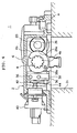
- a shift shaft 4 is rotatably supported in the inside of a housing 2, and a striker 6 is fitted on an outer periphery of the shift shaft 4 in a state that the striker 6 is movable in the axial direction of the shift shaft 4.
- the selecting operation of a transmission is performed by moving the striker 6 in the axial direction of the shift shaft 4, while the shifting operation of the transmission is performed by rotating the striker 6.
- a shift shaft holding hole 8 is formed and the shift shaft 4 is rotatably held in the holding hole 8.
- a U-shaped groove 4a is formed in an outer peripheral surface of the shift shaft 4, and a fixing pin 10 which is fixed to an inner surface of the above-mentioned holding hole 8 is fitted in the U-shaped groove 4a so as to restrict the movement of the shift shaft 4 in the axial direction while allowing the rotation of the shift shaft 4 about an axis thereof.
- a means which restricts the movement of the shift shaft 4 in the axial direction is not limited to the above-mentioned pin 10, and the other means may be used.
- a space 12 which surrounds the shift shaft 4 is formed, and the striker 6 is fitted on an outer periphery of a portion of the shift shaft 4 which is positioned in the inside of the space 12.
- Spline grooves 4b which extend in the axial direction are formed in an outer peripheral surface of a portion of the shift shaft 4 which is positioned in the space 12, while spline grooves 6a which extend in the axial direction are also formed in an inner peripheral surface of the striker 6, wherein these grooves 4b, 6a are engaged with each other, whereby the striker 6 is movable in the axial direction of the shift shaft 4 and, at the same time, is integrally rotatable with the shift shaft 4 in the rotational direction.
- Both end portions 4c, 4d of the shift shaft 4 are rotatably held by bearings 14, 15 which are arranged in both end portions 8a, 8b of the shift shaft holding hole 8.
- a selecting motor 16 is mounted on the housing 2 and a ball screw 20 is connected to a motor shaft 18 of the selecting motor 16, wherein the ball screw 20 is rotated by the driving of the selecting motor 16.
- the ball screw 20 is arranged parallel to the shift shaft 4 in a plane parallel to a mounting surface A (see Fig. 2 or 4) at which the above-mentioned housing 2 is fixed to the transmission 21 (see Fig. 4) .
- a portion close to an end portion 20b of the ball screw 20 opposite to an end portion (left end in Fig. 1) 20a connected to the selecting motor 16 side extends into the space 12 which surrounds the shift shaft 4, and the distal end portion 20b is supported in the inside of a support hole 22a formed in the housing 2 by way of a bearing 24.
- a ball nut (connecting member) 26 is threadedly mounted on a portion of the ball screw 20 which is positioned in the inside of the space 12.
- An engaging arcuate groove 26a (see Fig. 4) is formed in an outer surface of the ball nut 26, while a flange-shaped engaging projection 6b is formed on an outer surface of the striker 6, wherein the engaging projection 6b is engaged in the engaging groove 26a of the ball nut 26. Accordingly, upon the driving of the selecting motor 16, when the ball screw 20 which is connected to the motor shaft 18 is rotated, the ball nut 26 is moved on the ball screw 20 in the axial direction.
- the striker 6 In response to this movement of the ball nut 26, the striker 6 is moved on the shift shaft 4 in the axial direction and hence, the selecting operation of the transmission 21 is performed. Further, due to the engagement of the groove 26a of the ball nut 26 and the flange-shaped projection 6b of the striker 6, the rotation of the striker 6 is allowed.
- the selecting motor 16 is fixed to the housing 2 by way of a disc-like mounting plate 28 which is mounted on one end of the selecting motor 16, while the motor shaft 18 penetrates a ball bearing 30 which is arranged in the inside of a hole 28a formed in the center of a mounting plate 28 and extends into the inside of the housing 2.
- a rotation transmitting member 32 is connected to the motor shaft 18.
- a connecting hole 32a having a non-circular cross section is formed in the selecting motor 16 side of the rotation transmitting member 32, and a distal end of the motor shaft 18 having a shape similar to the shape of the connecting hole 32a is fitted in the mounting hole 32a and transmits the rotation.
- a shaft inserting hole 32b is formed in another end surface (right end surface in Fig. 1) of the rotation transmitting member 32, and the above-mentioned end portion 20a of the ball screw 20 is inserted into the inside of the shaft inserting hole 32b.
- An outer peripheral surface of the end portion 20a of the ball screw 20 and the above-mentioned shaft inserting hole 32b have a non-circular cross section in the same manner as the motor shaft 18 side so as to allow the transmission of the rotation as well as the movement of the ball screw 20 in the axial direction.
- a spring 34 for buffering is arranged between the distal end surface of the ball screw 20 and a stepped portion in the inside of the shaft inserting hole 32b.
- guide rods 36 are arranged parallel to the shift shaft 4 and the ball screw 20 on a side opposite to the ball screw 20 with the shift shaft 4 sandwiched between the guide rods 36 and the ball screw 20.
- Two guide rods 36 are arranged vertically as shown in Fig. 4 and a slide block 38 is slidably fitted on these two guide rods 36.
- the slide block 38 has the rotation thereof restricted by two upper and lower guide rods 36 and is movable in the same direction as an axis of the shift shaft 4.
- An engaging groove 38a is formed in a shift shaft 4 side of the above-mentioned slide block 38, and the above-mentioned flange-shaped engaging projection 6b which is formed on an outer surface of the striker 6 is engaged in the groove 38a. Due to the engagement of the groove 38a of the slide block 38 and the engaging projection 6b of the striker 6, the slide block 38 and the striker 6 are integrally moved in the axial direction and, at the same time, the rotation of the striker 6 is allowed.
- a rotational-angle-detection-type selecting sensor 40 is mounted to detect the selecting position of the striker 6.
- a U-shaped groove is formed in a distal end of a detecting lever 42 and a pin 44 (see Fig. 4) which is mounted on a lower end of the above-mentioned slide block 38 is engaged with the U-shaped groove and hence, in response to a position of the slide block 38 which is moved along with the movement of the striker 6 on the shift shaft 4 in the axial direction, the selecting position of the striker 6 is detected.
- a shifting motor 46 is mounted with a height different from a height of the shift shaft 4.
- the shifting motor 46 is arranged below a mounting surface A for the transmission 21 (see Fig. 3).
- a ball screw 52 is connected to a motor shaft 48 of the shifting motor 46 by way of a rotation transmitting member 50, and a ball nut (connecting member) 54 is threadedly mounted on the ball screw 52.
- a connecting portion of the rotation transmitting member 50, the motor shaft 48 and the ball screw 52 transmits the rotation due to the combination of non-circular cross sections in the same manner as the connecting portion of the above-mentioned selecting motor 16.
- a transmitting lever 56 is fixed to an end portion of the shift shaft 4 on a side opposite to the above-mentioned selecting motor 16, and a distal end (lower end) side of the transmitting lever 56 is engaged with a pair of engaging pins 54a mounted on both sides of the above-mentioned ball nut 54. Accordingly, when the shifting motor 46 is driven, the ball screw 52 is rotated by way of the motor shaft 48 and hence, the ball nut 54 is moved on the ball screw 52 in the axial direction. In response to the axial movement of the ball nut 54, the transmitting lever 56 is rotated. When the transmitting lever 56 is rotated, the shift shaft 4 and the striker 6 which is mounted on the shift shaft 4 by the spline engagement are integrally rotated. Accordingly, the shifting operation of the transmission 21 is performed.
- a rotational-angle-detection-type shift sensor 58 (see Fig. 2, the sensor 58 being omitted in Fig. 1) which detects the shift position of the striker 6 is mounted on the housing 2.
- a U-shaped groove is formed in a distal end of a detecting lever 60 and the groove is engaged with an engaging pin 62 which is fixed to an intermediate portion of the above-mentioned transmitting lever 56.
- the select sensor 40 is mounted on a slide-block-38-side side surface of the housing 2, and the engaging pin 44 which is fixed to the slide block 38 is connected to the detecting lever 42 of the select sensor 40. Accordingly, the moving position in the axial direction of the striker 6, that is, a selecting position of the transmission 21 is detected by the select sensor 40 by way of the movement of the slide block 38.
- a select sensor 40 of the conventional motor-driven-type transmission manipulating device detects a position of a nut which is threadedly mounted on a threaded shaft which is connected to a motor shaft of a selecting motor.
- the use of the nut generates a play between the nut and the threaded shaft and hence, the deviation is generated by an action of a rotational force whereby it is difficult to perform the highly accurate detection.
- the slide block 38 whose moving position is detected by the select sensor 40 is guided by two parallel guide rods 36, there is no possibility that the slide block 38 deviates. Accordingly, the slide block 38 moves in a stable posture and hence, it is possible to detect the select position with high accuracy.
- the motor shaft 48 is rotated by driving the shifting motor 46, and ball screw 52 is rotated by way of the rotation transmitting member 50. Due to the rotation of the ball screw 52, the ball nut 54 is moved in the axial direction of the ball screw 52 thus rotating the transmitting lever 56 and hence, the shaft shift 4 and the striker 6 are rotated whereby the shifting operation of the transmission 21 is performed.
- the shift position of the transmission 21 corresponding to the rotation of the striker 6 is detected by the shift sensor 58.
- the ball screw 20 which is rotated by the shift shaft 4 and the selecting motor 16 is arranged in the plane parallel to the mounting surface A for the transmission 21 of the housing 2 and hence, it is possible to minimize a height of the transmission manipulation device in the upward direction from the transmission 21 and, at the same time, it is possible to enhance the mountability of the transmission manipulation device on various vehicles.
- the shift shaft 4 and the ball screw 20 in the plane parallel to the mounting surface A for the transmission 21, it is possible to mount the selecting motor 16 in a state that the selecting motor 16 is arranged close to the mounting surface A.
- the selecting motor 16 When the distance between the selecting motor 16 and the mounting surface A is minimized, it is possible to arrange the selecting motor 16 such that a height of the center of the output shaft 18 of the selecting motor 16 from the mounting surface A becomes 1/2 of an outer diameter of a portion of the motor 16 having the largest outer diameter and hence, it is possible to extremely enhance the mountability of the transmission manipulating device on various vehicles.
- the flange-shaped projection 6b is mounted on the periphery of the striker 6, and the projection 6b is engaged with the grooves 26a, 38a which are respectively formed in the ball nut 26 which is fitted on the ball screw 20 rotated by the selecting motor 16 and the slide block 38 which has the position thereof detected by the select sensor 40. Accordingly, it is possible to make the whole motor-driven-type transmission manipulating device compact.
- the constitution which allows the connecting member (nut) to move in the axial direction by rotating the shaft using the selecting motor 16 and the shifting motor 46 is not limited to the use of the ball screw and may include the use of the combination of usual screw shaft and nut having trapezoidal threads.
Landscapes
- Engineering & Computer Science (AREA)
- General Engineering & Computer Science (AREA)
- Mechanical Engineering (AREA)
- Gear-Shifting Mechanisms (AREA)
- Details Of Spanners, Wrenches, And Screw Drivers And Accessories (AREA)
Applications Claiming Priority (2)
| Application Number | Priority Date | Filing Date | Title |
|---|---|---|---|
| JP2003345843A JP2005113956A (ja) | 2003-10-03 | 2003-10-03 | モーター駆動型変速機操作装置 |
| PCT/JP2004/000659 WO2005033556A1 (ja) | 2003-10-03 | 2004-01-26 | モーター駆動型変速機操作装置 |
Publications (1)
| Publication Number | Publication Date |
|---|---|
| EP1669643A1 true EP1669643A1 (de) | 2006-06-14 |
Family
ID=34419475
Family Applications (1)
| Application Number | Title | Priority Date | Filing Date |
|---|---|---|---|
| EP04705153A Withdrawn EP1669643A1 (de) | 2003-10-03 | 2004-01-26 | Motorgetriebene getriebebetätigungseinheit |
Country Status (5)
| Country | Link |
|---|---|
| EP (1) | EP1669643A1 (de) |
| JP (1) | JP2005113956A (de) |
| KR (1) | KR20060069873A (de) |
| CN (1) | CN1849476A (de) |
| WO (1) | WO2005033556A1 (de) |
Families Citing this family (9)
| Publication number | Priority date | Publication date | Assignee | Title |
|---|---|---|---|---|
| JP5472729B2 (ja) * | 2010-02-24 | 2014-04-16 | 株式会社ジェイテクト | 変速装置 |
| JP5728988B2 (ja) * | 2011-02-09 | 2015-06-03 | いすゞ自動車株式会社 | 自動変速装置のシフト制御装置 |
| JP5810543B2 (ja) * | 2011-02-09 | 2015-11-11 | いすゞ自動車株式会社 | 自動変速装置のシフト制御装置 |
| JP6084006B2 (ja) * | 2012-11-01 | 2017-02-22 | 三輪精機株式会社 | 変速機操作装置 |
| DE112015001436A5 (de) * | 2014-03-26 | 2016-12-08 | Schaeffler Technologies AG & Co. KG | Verfahren zur Bestimmung eines Betriebsmodus eines Getriebeaktors mit genau einem Motor |
| CN105889495A (zh) * | 2016-06-08 | 2016-08-24 | 陕西法士特齿轮有限责任公司 | 一种两个档位的自动操纵装置 |
| CN105909776A (zh) * | 2016-06-23 | 2016-08-31 | 陕西法士特齿轮有限责任公司 | 一种两档位操纵装置 |
| CN107504166B (zh) * | 2017-08-08 | 2019-03-22 | 广州汽车集团股份有限公司 | 位置检测机构及线控换挡执行器 |
| CN108953590B (zh) * | 2018-08-17 | 2020-06-30 | 清华大学 | 一种用于机械式自动变速箱的双换挡电机执行机构 |
Family Cites Families (4)
| Publication number | Priority date | Publication date | Assignee | Title |
|---|---|---|---|---|
| US4873881A (en) * | 1989-01-06 | 1989-10-17 | Eaton Corporation | Electrically actuated x-y shifting mechanism |
| JP2976177B2 (ja) * | 1995-02-24 | 1999-11-10 | 九州東芝機械株式会社 | ダブルナット間微小変位機構を備えたボールねじ装置 |
| US6588320B2 (en) * | 1999-12-30 | 2003-07-08 | Federal-Mogul World Wide, Inc. | Piston having uncoupled skirt |
| JP2003194215A (ja) * | 2001-12-25 | 2003-07-09 | Bosch Automotive Systems Corp | モータ駆動型変速機操作装置 |
-
2003
- 2003-10-03 JP JP2003345843A patent/JP2005113956A/ja active Pending
-
2004
- 2004-01-26 WO PCT/JP2004/000659 patent/WO2005033556A1/ja not_active Ceased
- 2004-01-26 EP EP04705153A patent/EP1669643A1/de not_active Withdrawn
- 2004-01-26 CN CNA2004800256718A patent/CN1849476A/zh active Pending
- 2004-01-26 KR KR1020067006388A patent/KR20060069873A/ko not_active Ceased
Non-Patent Citations (1)
| Title |
|---|
| See references of WO2005033556A1 * |
Also Published As
| Publication number | Publication date |
|---|---|
| KR20060069873A (ko) | 2006-06-22 |
| WO2005033556A1 (ja) | 2005-04-14 |
| CN1849476A (zh) | 2006-10-18 |
| JP2005113956A (ja) | 2005-04-28 |
Similar Documents
| Publication | Publication Date | Title |
|---|---|---|
| US8416040B2 (en) | Joystick device | |
| US8770056B2 (en) | Joystick device | |
| EP1669643A1 (de) | Motorgetriebene getriebebetätigungseinheit | |
| US11815179B2 (en) | Actuator for transmission | |
| KR101890599B1 (ko) | 변속 조작 기구 | |
| JP2011219002A (ja) | シフト装置 | |
| JP2007062664A (ja) | シフト装置 | |
| US6009769A (en) | Shift lock units for shift lever devices | |
| JP2007045390A (ja) | シフト装置 | |
| KR100464701B1 (ko) | 바이와이어방식의 차량용 시프트 레버장치 | |
| JP2005155849A (ja) | モーター駆動型変速機操作装置 | |
| KR101383174B1 (ko) | 동축 구동 다방향 제어장치 | |
| EP1705408A2 (de) | Handschaltgetriebe | |
| WO2009119819A1 (ja) | レンジ切換え装置 | |
| JP2006514727A (ja) | シフト操作装置 | |
| EP3680747A1 (de) | Bedienungselement | |
| CN108533729B (zh) | 一种变速器操纵装置 | |
| KR20110086288A (ko) | 자동화 수동 변속기용 작동기 | |
| EP3680746A1 (de) | Bedienungselement | |
| KR100379634B1 (ko) | 수동변속기의 시프트 레일 어셈블리 | |
| JP2006010009A (ja) | モーター駆動型変速機操作装置 | |
| WO2023017789A1 (ja) | 作業機 | |
| EP4552892A1 (de) | Bedieneinheit zur steuerung einer funktion einer maschine | |
| US10865876B2 (en) | Shift lever apparatus for vehicle | |
| JP2010195194A (ja) | シフトレバー装置 |
Legal Events
| Date | Code | Title | Description |
|---|---|---|---|
| PUAI | Public reference made under article 153(3) epc to a published international application that has entered the european phase |
Free format text: ORIGINAL CODE: 0009012 |
|
| 17P | Request for examination filed |
Effective date: 20060330 |
|
| AK | Designated contracting states |
Kind code of ref document: A1 Designated state(s): AT BE BG CH CY CZ DE DK EE ES FI FR GB GR HU IE IT LI LU MC NL PT RO SE SI SK TR |
|
| DAX | Request for extension of the european patent (deleted) | ||
| STAA | Information on the status of an ep patent application or granted ep patent |
Free format text: STATUS: THE APPLICATION HAS BEEN WITHDRAWN |
|
| 18W | Application withdrawn |
Effective date: 20100406 |