EP1669331B1 - Verfahren zur Herstellung eines nicht-beschlagenden Elements - Google Patents
Verfahren zur Herstellung eines nicht-beschlagenden Elements Download PDFInfo
- Publication number
- EP1669331B1 EP1669331B1 EP05026887A EP05026887A EP1669331B1 EP 1669331 B1 EP1669331 B1 EP 1669331B1 EP 05026887 A EP05026887 A EP 05026887A EP 05026887 A EP05026887 A EP 05026887A EP 1669331 B1 EP1669331 B1 EP 1669331B1
- Authority
- EP
- European Patent Office
- Prior art keywords
- substrate
- gas
- process according
- flame
- activation
- Prior art date
- Legal status (The legal status is an assumption and is not a legal conclusion. Google has not performed a legal analysis and makes no representation as to the accuracy of the status listed.)
- Expired - Lifetime
Links
Images

Classifications
-
- C—CHEMISTRY; METALLURGY
- C03—GLASS; MINERAL OR SLAG WOOL
- C03C—CHEMICAL COMPOSITION OF GLASSES, GLAZES OR VITREOUS ENAMELS; SURFACE TREATMENT OF GLASS; SURFACE TREATMENT OF FIBRES OR FILAMENTS MADE FROM GLASS, MINERALS OR SLAGS; JOINING GLASS TO GLASS OR OTHER MATERIALS
- C03C23/00—Other surface treatment of glass not in the form of fibres or filaments
- C03C23/0005—Other surface treatment of glass not in the form of fibres or filaments by irradiation
- C03C23/006—Other surface treatment of glass not in the form of fibres or filaments by irradiation by plasma or corona discharge
-
- B—PERFORMING OPERATIONS; TRANSPORTING
- B01—PHYSICAL OR CHEMICAL PROCESSES OR APPARATUS IN GENERAL
- B01J—CHEMICAL OR PHYSICAL PROCESSES, e.g. CATALYSIS OR COLLOID CHEMISTRY; THEIR RELEVANT APPARATUS
- B01J35/00—Catalysts, in general, characterised by their form or physical properties
- B01J35/30—Catalysts, in general, characterised by their form or physical properties characterised by their physical properties
- B01J35/39—Photocatalytic properties
-
- B—PERFORMING OPERATIONS; TRANSPORTING
- B01—PHYSICAL OR CHEMICAL PROCESSES OR APPARATUS IN GENERAL
- B01J—CHEMICAL OR PHYSICAL PROCESSES, e.g. CATALYSIS OR COLLOID CHEMISTRY; THEIR RELEVANT APPARATUS
- B01J37/00—Processes, in general, for preparing catalysts; Processes, in general, for activation of catalysts
- B01J37/02—Impregnation, coating or precipitation
- B01J37/0238—Impregnation, coating or precipitation via the gaseous phase-sublimation
-
- B—PERFORMING OPERATIONS; TRANSPORTING
- B01—PHYSICAL OR CHEMICAL PROCESSES OR APPARATUS IN GENERAL
- B01J—CHEMICAL OR PHYSICAL PROCESSES, e.g. CATALYSIS OR COLLOID CHEMISTRY; THEIR RELEVANT APPARATUS
- B01J37/00—Processes, in general, for preparing catalysts; Processes, in general, for activation of catalysts
- B01J37/34—Irradiation by, or application of, electric, magnetic or wave energy, e.g. ultrasonic waves ; Ionic sputtering; Flame or plasma spraying; Particle radiation
- B01J37/349—Irradiation by, or application of, electric, magnetic or wave energy, e.g. ultrasonic waves ; Ionic sputtering; Flame or plasma spraying; Particle radiation making use of flames, plasmas or lasers
-
- B—PERFORMING OPERATIONS; TRANSPORTING
- B60—VEHICLES IN GENERAL
- B60R—VEHICLES, VEHICLE FITTINGS, OR VEHICLE PARTS, NOT OTHERWISE PROVIDED FOR
- B60R1/00—Optical viewing arrangements; Real-time viewing arrangements for drivers or passengers using optical image capturing systems, e.g. cameras or video systems specially adapted for use in or on vehicles
- B60R1/02—Rear-view mirror arrangements
- B60R1/06—Rear-view mirror arrangements mounted on vehicle exterior
- B60R1/0602—Rear-view mirror arrangements mounted on vehicle exterior comprising means for cleaning or deicing
-
- C—CHEMISTRY; METALLURGY
- C03—GLASS; MINERAL OR SLAG WOOL
- C03B—MANUFACTURE, SHAPING, OR SUPPLEMENTARY PROCESSES
- C03B29/00—Reheating glass products for softening or fusing their surfaces; Fire-polishing; Fusing of margins
- C03B29/04—Reheating glass products for softening or fusing their surfaces; Fire-polishing; Fusing of margins in a continuous way
- C03B29/06—Reheating glass products for softening or fusing their surfaces; Fire-polishing; Fusing of margins in a continuous way with horizontal displacement of the products
- C03B29/08—Glass sheets
-
- C—CHEMISTRY; METALLURGY
- C03—GLASS; MINERAL OR SLAG WOOL
- C03C—CHEMICAL COMPOSITION OF GLASSES, GLAZES OR VITREOUS ENAMELS; SURFACE TREATMENT OF GLASS; SURFACE TREATMENT OF FIBRES OR FILAMENTS MADE FROM GLASS, MINERALS OR SLAGS; JOINING GLASS TO GLASS OR OTHER MATERIALS
- C03C17/00—Surface treatment of glass, not in the form of fibres or filaments, by coating
- C03C17/22—Surface treatment of glass, not in the form of fibres or filaments, by coating with other inorganic material
- C03C17/23—Oxides
- C03C17/245—Oxides by deposition from the vapour phase
- C03C17/2456—Coating containing TiO2
-
- B—PERFORMING OPERATIONS; TRANSPORTING
- B01—PHYSICAL OR CHEMICAL PROCESSES OR APPARATUS IN GENERAL
- B01J—CHEMICAL OR PHYSICAL PROCESSES, e.g. CATALYSIS OR COLLOID CHEMISTRY; THEIR RELEVANT APPARATUS
- B01J21/00—Catalysts comprising the elements, oxides, or hydroxides of magnesium, boron, aluminium, carbon, silicon, titanium, zirconium, or hafnium
- B01J21/06—Silicon, titanium, zirconium or hafnium; Oxides or hydroxides thereof
- B01J21/063—Titanium; Oxides or hydroxides thereof
-
- C—CHEMISTRY; METALLURGY
- C03—GLASS; MINERAL OR SLAG WOOL
- C03C—CHEMICAL COMPOSITION OF GLASSES, GLAZES OR VITREOUS ENAMELS; SURFACE TREATMENT OF GLASS; SURFACE TREATMENT OF FIBRES OR FILAMENTS MADE FROM GLASS, MINERALS OR SLAGS; JOINING GLASS TO GLASS OR OTHER MATERIALS
- C03C2217/00—Coatings on glass
- C03C2217/70—Properties of coatings
- C03C2217/71—Photocatalytic coatings
-
- C—CHEMISTRY; METALLURGY
- C03—GLASS; MINERAL OR SLAG WOOL
- C03C—CHEMICAL COMPOSITION OF GLASSES, GLAZES OR VITREOUS ENAMELS; SURFACE TREATMENT OF GLASS; SURFACE TREATMENT OF FIBRES OR FILAMENTS MADE FROM GLASS, MINERALS OR SLAGS; JOINING GLASS TO GLASS OR OTHER MATERIALS
- C03C2217/00—Coatings on glass
- C03C2217/70—Properties of coatings
- C03C2217/75—Hydrophilic and oleophilic coatings
-
- C—CHEMISTRY; METALLURGY
- C03—GLASS; MINERAL OR SLAG WOOL
- C03C—CHEMICAL COMPOSITION OF GLASSES, GLAZES OR VITREOUS ENAMELS; SURFACE TREATMENT OF GLASS; SURFACE TREATMENT OF FIBRES OR FILAMENTS MADE FROM GLASS, MINERALS OR SLAGS; JOINING GLASS TO GLASS OR OTHER MATERIALS
- C03C2218/00—Methods for coating glass
- C03C2218/10—Deposition methods
- C03C2218/15—Deposition methods from the vapour phase
- C03C2218/152—Deposition methods from the vapour phase by cvd
-
- C—CHEMISTRY; METALLURGY
- C03—GLASS; MINERAL OR SLAG WOOL
- C03C—CHEMICAL COMPOSITION OF GLASSES, GLAZES OR VITREOUS ENAMELS; SURFACE TREATMENT OF GLASS; SURFACE TREATMENT OF FIBRES OR FILAMENTS MADE FROM GLASS, MINERALS OR SLAGS; JOINING GLASS TO GLASS OR OTHER MATERIALS
- C03C2218/00—Methods for coating glass
- C03C2218/30—Aspects of methods for coating glass not covered above
- C03C2218/32—After-treatment
Definitions
- the invention relates to a method for producing an element in which a surface layer of a photocatalytic material is subjected to an activation step.
- the hydrophilicity can be determined, for example, based on the so-called contact angle, which forms the edge of a water droplet located on the element surface with the element surface. In the case of uncoated glasses, this contact angle is usually between about 40 ° and 60 °. By contrast, a hydrophilic surface is then spoken of when the contact angle is less than approximately 20 °. At large contact angles of, for example, more than 100 °, however, one speaks of hydrophobic surfaces. The so-called super-hydrophilicity, however, exists when the edge or contact angle is less than about 10 °, preferably less than about 5 °.
- a hydrophilic or super-hydrophilic surface of a glass in this sense means that, when wetted with water, for example as a result of condensation, a relatively homogeneous water film is formed directly from the water droplets that occur.
- a homogeneous water film influences the passage of light through the glass only insignificantly, so that the user no significant clouding or impairment occurs.
- a non-fogging element by applying a hydrophilic surface coating on a glass substrate
- a hydrophilic surface coating on a glass substrate
- it is for example from DE 296 23 901 U1 or from the EP 1 254 870 A2
- TiO 2 titanium dioxide
- the photocatalytic material acts in such a way that it makes the surface of the coating hydrophilic in the above-mentioned sense.
- a substantially transparent coating of a substrate is formed on the substrate photocatalytic material is applied, which makes the surface of the element hydrophilic after photoexcitation.
- a so-called activation of the coating is required.
- the irradiation of the coating is provided with a suitable light source, wherein the wavelength of the light used should have an energy which is higher than the bandgap energy of the photocatalyst.
- a concept for activating a surface layer by UV light is also from EP 1 254 870 A2 known.
- the invention is therefore based on the object of specifying a method for producing a non-fogging element of the type mentioned above, which is particularly suitable in view of the time required for the activation of the surface coating treatment time and the associated effort for a large-scale production.
- This object is achieved in that the surface layer is flamed in the implementation of the activation step with a gas flame.
- the invention is based on the consideration that a production method which is also suitable for mass production should be particularly consistently oriented towards comparatively short treatment times of individual elements and particularly low energy consumption.
- the previously considered unavoidable Photo excitation of the surface layer to provide the hydroxyl groups is basically replaceable by pretreatment of the surface layer on chemical Basis, which can be adjusted by suitable choice of reactants and conditions particularly short treatment times. Therefore, the implementation of the chemical-based activation step is provided wherein the surface layer is reactively treated by treating the coating with a gas flame.
- the element could be substantially completely formed from the photocatalytic material.
- the surface layer is formed by a coating of the photocatalytic material applied to a substrate, so that, in particular, use as a vehicle mirror or the like comes into consideration.
- the substrate provided with the coating can also be subjected to a subsequent activation step, in particular in the manner of an intermediate product.
- the method is used for producing a non-fogging element, in which a substantially transparent coating of the photocatalytic material is applied to the substrate, which makes the surface of the element hydrophilic after a photoexcitation.
- the substrate coated with the photocatalytic material is advantageously conducted past the gas flame, the gas flame being positioned in this way is that the flame tip is slightly, preferably about 10 mm to 20 mm, above the substrate surface. Due to the oxidizing properties of a gas flame, the presence of free radicals (eg hydroxyl radicals HO - , hydroperoxyl radical HOO - and hydroperoxyl radical anions HOO - ) and the water vapor liberated during combustion, the best results are achieved by directly contacting the flame tip with the substrate surface expected. The application of the gas flame to the substrate preferably takes place on the coated side.
- free radicals eg hydroxyl radicals HO - , hydroperoxyl radical HOO - and hydroperoxyl radical anions HOO -
- a particularly high level of effectiveness in the treatment of the coated substrates can be achieved by advantageously passing the substrate past the gas flame at a speed between 0.1 and 10 cm / s, preferably at about 2.5 cm / s.
- the flaming of the surface takes place by means of a number of slot burners.
- the one or more gas burners are advantageously exaggerated with excess air, so that the burner flame is guided blue.
- the gas flame is advantageously supplied to a fuel gas stream and an oxidant stream, wherein the quantitative ratio is set appropriately.
- the ratio of oxidant stream in particular air
- fuel gas stream is set to a value of more than 10, so that a comparatively clearly pronounced excess air is maintained.
- the activation step is carried out in an ambient atmosphere or under a protective gas atmosphere.
- Titanium dioxide (TiO 2 ) has proven to be particularly favorable for the intended use as a photocatalytic material or as a hydrophilic surface coating with regard to the choice of material. As a photocatalytic material is therefore advantageously applied to the substrate, a titanium dioxide coating.
- the non-fogging element may be provided for any purpose, such as a windshield in a motor vehicle, as a window in the outer facade of a building, as a traffic mirror, as a lens or the like.
- a non-fogging element is a mirror, preferably for use in a motor vehicle.
- a conveying device for the element may be provided, to which a device for the reactive treatment of the surface layer is assigned.
- a number of gas burners are provided.
- the or each gas burner is preferably positioned relative to the conveyor such that the visible flame tip of the gas flame is slightly preferably about 10 mm to 20 mm above the surface of a passing substrate. This ensures that particularly reliable and stable, reproducible treatment results can be achieved by the oxidizing properties of the gas flame, the presence of free radicals and the water vapor released during combustion.
- the device can be designed by a suitable choice of the conveyor for the sequential treatment of a plurality of individual elements.
- it may also be provided to treat comparatively large-area, curved or curved elements.
- These may be, in particular, what are known as calottes, from which, for example, exterior mirrors for passenger cars, for lorries or buses are manufactured.
- a plurality of gas burners is preferably provided, which in terms of Positioning and orientation of their outlet openings are arranged adapted to a contour provided for the substrate contouring.
- an activation of calottes may be provided, wherein a plurality of individual burners are arranged according to the contour of the dome.
- an additional equalization of the activation can be achieved by rotating the calotte during the flame treatment. If there is a different circumferential speed of the calotte (outside / inside), it is preferable to compensate for the resulting inhomogeneities by different burner intensities or auxiliary burners.
- a device for the reactive treatment of a substrate in particular a gas burner, is used for activating a substantially transparent coating of a photocatalytic material applied to a substrate.
- the advantages achieved by the invention are, in particular, that by activating the surface layer by reactive means, the disadvantages associated with the otherwise required photo-activation, in particular with regard to the associated energy requirement and the required duration of treatment, can be avoided.
- the reactive treatment of the surface layer for example, a typical transit time of the coated substrate by the activation of about 3 h (in a photo-activation by UV irradiation) to a treatment time of about 6 s (reactive treatment by gas flame) can be reduced.
- the specific energy requirement for activation can be reduced from about 200 watt-hours per mirror (photoactivation by UV irradiation) to about 2 watt-hours per mirror (reactive treatment by gas flame) in the manufacture of coated mirrors for the automotive industry Treatment, characteristic of the degree of hydrophilicity contact angle as well as its temporal evolution after completion of activation for both cases are comparable.
- the device 1 after Fig. 1 is provided for the so-called activation of a substrate 2 coated with a photocatalytic material.
- the substrate 2 which is provided in the exemplary embodiment for the production of rear-view mirrors for motor vehicles and accordingly consists essentially of glass in its base body, is provided on its surface with a coating which has hydrophilic or super-hydrophilic properties and thus wetting with Water forms a comparatively homogeneous water film, which affects the passage of light through the glass only insignificantly.
- the substrate 2 is coated prior to its supply to the device 1 in a conventional manner with a photocatalytic semiconductor material, titanium dioxide in the embodiment.
- CVD Chemical Vapor Reduction
- sol-gel coating etc.
- the application of the coating can in particular according to the in the DE 296 23 901 U1 or in the EP 1 254 870 A2 described concepts on the substrate 2, wherein the relevant disclosure of said documents is expressly included.
- Such a substrate 2 provided with a titanium dioxide coating basically has super-hydrophilic properties on the coated surface. This is maintained for a certain period even when the substrate 2 is stored in the dark. However, the hydrophilicity is gradually lost over time, but can be restored in a relatively simple manner by subjecting the surface to photoexcitation, for example, by daylight.
- the formation of the super-hydrophilicity in the surface of the coated substrate 2 and thus the production of a non-fogging element formed by the coated substrate 2 presupposes that the coated substrate 2 is subjected to a so-called activation step after the application of the titanium dioxide coating .
- the super-hydrophilicity of the surface coating in a treatment step before the first use of the substrate 2, the super-hydrophilicity of the surface coating must be adjusted by a suitable treatment, wherein it is assumed that in this step, a sufficient number of hydroxyl groups in the surface coating is provided, which can produce the desired superhydrophilicity ,
- the device 1 is designed specifically.
- the device 1 is provided in particular for use in a large-scale production and accordingly designed for particularly short treatment times for the coated substrates 2 and comparatively high throughput rates with only limited energy consumption.
- the device 1 is designed to activate the coated substrates 2 by a reactive treatment.
- Such reactive treatment is carried out according to the design in particular in that the device 1 by passing the coated substrate 2 by appropriate adjustment of environmental conditions and parameters reactive radicals or substances are supplied to the (consecutive chemical reactions on oxidation by means of hot oxygen, HOO -, OH Radicals) the surface of the coating of adhering impurities and ultimately produce a sufficient number of hydroxyl groups on the coated surface.
- the device 1 is designed to treat the surface coating applied to the substrate 2 with a gas flame to carry out the activation step.
- the device 1 comprises a gas burner 4 as a device for the reactive treatment of the coated substrate 2.
- This is assigned a conveying device 6 for the coated substrate 2, via which the coated substrate 2 can be suitably guided past the gas burner 4.
- the gas burner 4 both a fuel gas B and an oxidant O can be supplied.
- fuel gas B can be provided, for example, methane, ethane, ethylene, acetylene, propane, butane, natural gas, hydrogen, mixtures or the like.
- the operating parameters of the gas burner 4 are adjusted in particular such that a particularly good treatment success is achieved on the coated substrate 2.
- the knowledge is taken into account that the best results of the treatment are expected from the oxidizing properties of the burner flame 10, the presence of free radicals and the water vapor released during combustion in direct contact of the flame tip with the substrate surface.
- the gas burner 4 is positioned relative to the conveyor 6 such that the flame tip of the burner flame 10 is about 15 mm above the surface of the passing substrate 2.
- the cleaning of slightly soiled surfaces which were subjected, for example, a pre-cleaning by a suitable washing device, succeeds in just a few seconds.
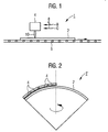
- a contoured present substrate 2 in the alternative embodiment according to Fig. 2 is the device 1 'for a treatment of a contoured present substrate 2, so for example a dome designed.
- a plurality of gas burners 4 are provided in the device 1 ', which are arranged with respect to the positioning of their outlet openings adapted to the contouring provided for the substrate 2.
- a rotation of the calottes is provided during the flame treatment so that a particularly uniform activation is achieved over the entire surface.
- a possibly present different peripheral speed of the dome is thereby optionally by appropriately set different burner intensities or in Fig. 2 not shown additional burners compensated.
- the gas flows of the fuel gas B and the oxidant O are each separately adjustable, so that operating point dependent a particularly favorable ratio of the two gas streams can be adjusted. For particularly good treatment results, this ratio is adjusted so that the burner flame out blue, ie with excess air, operated.
- the substrate 2 is guided past the burner flame 10 at a speed between 0.1 and 10 cm / s, preferably at about 2.5 cm / s.
- FIG. 3 in the form of a diagram depicting the dependence of the so-called contact angle ⁇ on the ratio V between oxidant flow (or air flow) and fuel gas flow.
- the contact angle ⁇ which is drawn here as a measure of the hydrophilicity of the coated substrate 2, is the angle formed by the edge of a water droplet located on the element surface with the element surface. In the case of uncoated glasses, this contact angle is usually between about 40 ° and 60 °.
- a hydrophilic surface becomes then spoken, if the contact angle is less than about 20 °.
- the so-called super-hydrophilicity exists when the edge or contact angle is less than about 10 °, preferably less than about 5 °.
- This contact angle ⁇ is shown in the diagram Fig. 3 applied as a function of the ratio V for a coating system in which as a gas burner 4, a belt burner with the type designation SK 02-380 - 003
- the company Webber is used with a cast iron body, flame strips made of stainless steel fins and a width of 200 mm, which can be operated with natural gas under a pre-pressure of 70 mbar and air under a pressure of 6 bar.
- the contact angle ⁇ decreases from a ratio value V of about 10, ie a clear excess of air, to values below about 10 °, so that so-called super-hydrophilicity of the coated substrates 2 can be achieved.
Landscapes
- Chemical & Material Sciences (AREA)
- Engineering & Computer Science (AREA)
- Organic Chemistry (AREA)
- Materials Engineering (AREA)
- Chemical Kinetics & Catalysis (AREA)
- Life Sciences & Earth Sciences (AREA)
- General Chemical & Material Sciences (AREA)
- Geochemistry & Mineralogy (AREA)
- Physics & Mathematics (AREA)
- Toxicology (AREA)
- Health & Medical Sciences (AREA)
- Plasma & Fusion (AREA)
- Optics & Photonics (AREA)
- Multimedia (AREA)
- Mechanical Engineering (AREA)
- Catalysts (AREA)
- Surface Treatment Of Glass (AREA)
- Acyclic And Carbocyclic Compounds In Medicinal Compositions (AREA)
- Weting (AREA)
- Formation Of Insulating Films (AREA)
Description
- Die Erfindung bezieht sich auf ein Verfahren zur Herstellung eines Elements, bei dem eine Oberflächenschicht aus einem photokatalytischen Material einem Aktivierungsschritt unterzogen wird.
- In einer Vielzahl von Anwendungen von Gläsern, wie beispielsweise in Rückspiegeln oder Windschutzscheiben von Kraftfahrzeugen, bei Fensterscheiben von Gebäuden, bei Verkehrsspiegeln, für Linsen oder in Abdeckgläsern für Instrumente, ist es wünschenswert, das jeweilige Glas auch bei vergleichsweise niedrigen Umgebungstemperaturen und hoher Umgebungsfeuchtigkeit beschlagfrei zu halten. Für Gläser ist dies im Sinne der Herstellung eines nicht-beschlagenden Elements erreichbar, indem die Oberfläche mit einer Antibeschlags-Beschichtung versehen wird, die üblicherweise so genannte hydrophile oder super-hydrophile Eigenschaften aufweist.
- Die Hydrophilie ist dabei beispielsweise anhand des so genannten Kontaktwinkels bestimmbar, den der Rand eines sich auf der Elementoberfläche befindlichen Wassertropfens mit der Elementoberfläche bildet. Im Falle unbeschichteter Gläser beträgt dieser Randwinkel üblicherweise etwa zwischen 40° und 60°. Von einer hydrophilen Oberfläche wird demgegenüber dann gesprochen, wenn der Randwinkel kleiner als etwa 20° ist. Bei großen Randwinkeln von beispielsweise mehr als 100° spricht man hingegen von hydrophoben Oberflächen. Die so genannte Super-Hydrophilie liegt hingegen vor, wenn der Rand- oder Kontaktwinkel weniger als etwa 10°, vorzugsweise weniger als etwa 5°, beträgt.
- Eine in diesem Sinne hydrophile oder super-hydrophile Oberfläche eines Glases führt dazu, dass bei einer Benetzung mit Wasser, beispielsweise in Folge von Kondensation, aus den auftretenden Wassertropfen unmittelbar ein vergleichsweise homogener Wasserfilm gebildet wird. Im Gegensatz zur Anwesenheit von einzelnen, individualisierbaren Wassertropfen auf der Glasoberfläche, die insbesondere unregelmäßige Form und Größe aufweisen können, beeinflusst ein derartiger homogener Wasserfilm den Durchgang von Licht durch das Glas nur unwesentlich, so dass für den Benutzer keine nennenswerte Eintrübung oder Beeinträchtigung entsteht. Durch die Aufbringung einer hydrophilen Oberflächenbeschichtung kann ein Glas somit beschlagfrei im oben genannten Sinne gemacht werden.
- Zu diesem Zweck, also zur Herstellung eines nicht-beschlagenden Elements durch Aufbringung einer hydrophilen Oberflächenbeschichtung auf ein Glas-Substrat, ist es beispielsweise aus der
DE 296 23 901 U1 oder aus derEP 1 254 870 A2 bekannt, ein Substrat mit einer im Wesentlichen transparenten Beschichtung aus einem photokatalytischen Material, insbesondere mit Titandioxid (TiO2), zu versehen. Das photokatalytische Material wirkt dabei derart, dass es die Oberfläche der Beschichtung hydrophil im oben genannten Sinne macht. Dabei wird vermutet, dass unter der photokatalytischen Wirkung des photokatalytischen Materials in Folge einer Bestrahlung mit Licht einer geeigneten Wellenlänge Hydroxylradikale (OH+), durch Folgereaktion Hydroperoxyradikale (HOO-) und Peroxylradikalanionen (O2 -) an der Oberfläche gebildet werden, die die an der Oberfläche der Beschichtung anhaftenden organisch chemischen Verbindungen oxidieren können. Hierbei wird in einer Reaktionskaskade, an der auch Wasser und Sauerstoff aus der Luft beteiligt sind, letztendlich Kohlendioxid und Wasser gebildet. Auf diese Weise wird die Oberfläche der Beschichtung von Fetten, Ölen oder sonstigen organisch chemischen Verunreinigungen befreit, so dass letztendlich nur physisorbiertes Wasser zusammen mit den endständigen OH-Gruppen der Beschichtung übrig bleibt, wodurch die Beschichtung hydrophil wird. - Bei der Herstellung eines derartigen, nicht-beschlagenden Elements wird somit auf das Substrat eine im Wesentlichen transparente Beschichtung aus einem photokatalytischen Material aufgebracht, das nach einer Photoanregung die Oberfläche des Elements hydrophil macht. Zum erstmaligen Einsatz eines derartigen nicht-beschlagenden Elements ist zudem noch eine so genannte Aktivierung der Beschichtung erforderlich. Beim Konzept nach der
DE 296 23 901 U1 ist für diese Aktivierung die Bestrahlung der Beschichtung mit einer geeigneten Lichtquelle vorgesehen, wobei die Wellenlänge des verwendeten Lichts eine Energie aufweisen soll, die höher ist als die Bandlückenenergie des Photokatalysators. Alternativ ist ein Konzept zur Aktivierung einer Oberflächenschicht durch UV-Licht auch aus derEP 1 254 870 A2 bekannt. Sobald in Folge dieser Aktivierung die Oberfläche der photokatalytischen Beschichtung hydrophil oder super-hydrophil gemacht worden ist, bleibt die Hydrophilie der Oberfläche für eine bestimmte Zeitspanne auch dann erhalten, wenn das Substrat im Dunkeln aufbewahrt wird. Allerdings geht die Hydrophilie im Laufe der Zeit allmählich verloren, was insbesondere sich an den Hydroxylgruppen der Beschichtungsoberfläche anlagernden Verunreinigungen zugeschrieben wird. Die Hydrophilie und somit die Beschlagsfreiheit des Elements kann dabei jedoch auf vergleichsweise einfache Weise wieder hergestellt werden, indem die Oberfläche erneut einer Photoanregung unterworfen wird. Hinsichtlich dieser "Auffrischung" der Oberflächen-Hydrophilie sind die Anforderungen bei der Bestrahlung hinsichtlich Bestrahlungsintensität und -dauer deutlich geringer als bei der erstmaligen Aktivierung. Beispielsweise kann es bei der Verwendung eines derartigen nicht-beschlagenden Elements im Rückspiegel eines Kraftfahrzeugs für eine Re-Aktivierung der hydrophilen Oberflächenbeschichtung durchaus ausreichend sein, das Kraftfahrzeug über einen Zeitraum von einigen wenigen Stunden im Tageslicht zu bewegen, um die vollständige hydrophile Eigenschaft der Oberflächenbeschichtung wieder herzustellen. - Vergleichsweise aufwändig bei der Herstellung eines derartigen nicht-beschlagenden Elements ist jedoch der Aktivierungsschritt zur erstmaligen Aktivierung der photokatalytischen Oberflächenbeschichtung. Hierzu ist es in der Regel erforderlich, das Substrat nach dem Aufbringen der photokatalytischen Beschichtung über einen Zeitraum von mehreren Stunden mit einer Intensität von einigen hundert Watt pro Quadratmeter mit UV-Licht zu bestrahlen. Sowohl hinsichtlich der erforderlichen Behandlungszeit als auch hinsichtlich des mit der Behandlung verbundenen Energiebedarfs ist diese Aktivierung für einen industriellen Fertigungsprozess derartiger nicht-beschlagender Elemente, insbesondere in Großserienproduktion, daher vergleichsweise ungünstig.
- Der Erfindung liegt daher die Aufgabe zugrunde, ein Verfahren zur Herstellung eines nicht-beschlagenden Elements der oben genannten Art anzugeben, das im Hinblick auf die für die Aktivierung der Oberflächenbeschichtung erforderliche Behandlungsdauer und den damit verbundenen Aufwand auch für eine Großserienproduktion besonders geeignet ist.
- Diese Aufgabe wird erfindungsgemäß dadurch gelöst, dass die Oberflächenschicht bei der Durchführung des Aktivierungsschritts mit einer Gasflamme beflammt wird.
- Dabei ist insbesondere vorgesehen, dass für die Aktivierung der Oberfläche während des Aktivierungsschritts hinsichtlich der Umgebungsbedingungen (beispielsweise Temperatur, Druck) und möglicher Reaktionspartner für die Oberflächenschicht geeignete Bedingungen eingestellt werden, so dass die mit der Aktivierung beabsichtigte Bereitstellung der Hydroxylgruppen an der Oberfläche in Folge chemischer Reaktionen erfolgen kann.
- Die Erfindung geht dabei von der Überlegung aus, dass ein auch für die Großserienproduktion geeignetes Herstellungsverfahren besonders konsequent auf vergleichsweise kurze Behandlungszeiten einzelner Elemente und besonders gering gehaltenen Energieverbrauch hin ausgerichtet sein sollte. Wie sich überraschenderweise herausgestellt hat, ist die bisher für unumgänglich gehaltene Photoanregung der Oberflächenschicht zur Bereitstellung der Hydroxylgruppen grundsätzlich ersetzbar durch eine Vorbehandlung der Oberflächenschicht auf chemischer Basis, wobei durch geeignete Wahl von Reaktionspartnern und -bedingungen besonders kurze Behandlungszeiten eingestellt werden können. Daher ist die Durchführung des Aktivierungsschritts auf chemischer Basis vorgesehen, wobei die Oberflächenschicht reaktiv behandelt wird, indem die Behandlung der Beschichtung mit einer Gasflamme erfolgt.
- Das Element könnte dabei im Wesentlichen vollständig aus dem photokatalytischen Material gebildet sein. Vorteilhafterweise ist die Oberflächenschicht jedoch durch eine auf einem Substrat aufgebrachte Beschichtung aus dem photokatalytischen Material gebildet, so dass insbesondere eine Verwendung als Kfz-Spiegel oder dergleichen in Betracht kommt. Das mit der Beschichtung versehene Substrat kann dabei insbesondere in der Art eines Zwischenprodukts auch einem nachträglichen Aktivierungsschritt unterzogen werden. Vorteilhafterweise wird das Verfahren zur Herstellung eines nicht beschlagenden Elements eingesetzt, bei dem auf dem Substrat eine im Wesentlichen transparente Beschichtung aus dem photokatalytischen Material aufgebracht wird, das nach einer Photoanregung die Oberfläche des Elements hydrophil macht.
- Zur Aktivierung der Oberflächenbeschichtung über die Beflammung mit einer Gasflamme wird das mit dem photokatalytischen Material beschichtete Substrat vorteilhafterweise an der Gasflamme vorbeigeführt, wobei die Gasflamme derart positionert wird, dass die Flammenspitze geringfügig, vorzugsweise etwa 10 mm bis 20 mm, oberhalb der Substratoberfläche steht. Bedingt durch die oxidierenden Eigenschaften einer Gasflamme, dem Vorhandensein freier Radikale (z. B. Hydroxylradikale HO-, Hydroperoxylradikale HOO- und Hydroperoxylradikalanionen HOO-) und dem bei der Verbrennung frei werdenden Wasserdampf werden nämlich beim direkten Kontakt der Flammenspitze mit der Substratoberfläche die besten Behandlungsergebnisse erwartet. Die Beaufschlagung des Substrats mit der Gasflamme erfolgt dabei bevorzugt auf der beschichteten Seite.
- Eine besonders hohe Effektivität bei der Behandlung der beschichteten Substrate ist erreichbar, indem das Substrat vorteilhafterweise mit einer Geschwindigkeit zwischen 0,1 und 10 cm/s, bevorzugt bei etwa 2,5 cm/s, an der Gasflamme vorbeigeführt wird.
- Vorzugsweise erfolgt das Beflammen der Oberfläche mittels einer Anzahl von Schlitzbrennern. Der oder die Gasbrenner werden vorteilhafterweise mit Luftüberschuss übertrieben, so dass die Brennerflamme blau geführt wird. Dazu wird der Gasflamme vorteilhafterweise ein Brenngasstrom und ein Oxidationsmittelstrom zugeführt, wobei das Mengenverhältnis geeignet eingestellt wird. Vorzugsweise wird dabei für das Verhältnis von Oxidationsmittelstrom, insbesondere Luft, und Brenngasstrom auf einen Wert von mehr als 10 eingestellt, so dass ein vergleichsweise deutlich ausgeprägter Luftüberschuss eingehalten wird.
- Vorteilhafterweise wird der Aktivierungsschritt in Umgebungsatmosphäre oder unter Schutzgasatmosphäre durchgeführt.
- Als besonders günstig für den beabsichtigten Einsatzzweck als photokatalytisches Material oder als hydrophile Oberflächen-Beschichtung hat sich hinsichtlich der Materialwahl Titandioxid (TiO2) ergeben. Als photokatalytisches Material wird daher vorteilhafterweise auf das Substrat eine Titandioxid-Beschichtung aufgebracht.
- Das nicht-beschlagende Element kann zu beliebigen Einsatzzwecken, beispielsweise als Windschutzscheibe in einem Kraftfahrzeug, als Fensterscheibe in der Außenfassade eines Gebäudes, als Verkehrsspiegel, als Linse oder dergleichen vorgesehen sein. In besonders bevorzugter Ausgestaltung wird jedoch als nichtbeschlagendes Element ein Spiegel, vorzugsweise zum Einsatz in einem Kraftfahrzeug, hergestellt.
- Zur Aktivierung einer Oberflächenschicht aus einem photokatalytischen Material eines Elements kann eine Fördereinrichtung für das Element vorgesehen sein, der eine Einrichtung zur reaktiven Behandlung der Oberflächenschicht zugeordnet ist. Als Einrichtung zur reaktiven Behandlung des beschichteten Substrats ist eine Anzahl von Gasbrennern vorgesehen.
- Der oder jeder Gasbrenner ist dabei vorzugsweise relativ zur Fördereinrichtung derart positioniert, dass die sichtbare Flammenspitze der Gasflamme geringfügig vorzugsweise etwa 10 mm bis 20 mm, oberhalb der Oberfläche eines vorbeigeführten Substrats steht. Damit ist sichergestellt, dass durch die oxidierenden Eigenschaften der Gasflamme, dem Vorhandensein freier Radikale und dem bei der Verbrennung frei werden Wasserdampf besonders zuverlässige und stabile, reproduzierbare Behandlungsergebnisse erreichbar sind.
- Die Einrichtung kann durch eine geeignete Wahl der Fördereinrichtung zur sequentiellen Behandlung einer Vielzahl einzelner Elemente ausgestaltet sein. Insbesondere kann auch vorgesehen sein, vergleichsweise großflächige, in sich gewölbte oder gekrümmte Elemente, zu behandeln. Dabei kann es sich insbesondere um so genannte Kalotten, aus denen beispielsweise Außenspiegel für Pkw, für Lastkraftfahrzeuge oder Omnibusse hergestellt werden, handeln. Um bei derartigen Einsatzgebieten eine flächige gleichmäßige Aktivierung zu gewährleisten, ist vorzugsweise eine Mehrzahl von Gasbrennern vorgesehen, die hinsichtlich der Positionierung und Orientierung ihrer Austrittsöffnungen an eine für das Substrat vorgesehene Konturierung angepasst angeordnet sind. Insbesondere kann dabei eine Aktivierung von Kalotten vorgesehen sein, wobei mehrere Einzelbrenner entsprechend der Kontur der Kalotte angeordnet sind. Dabei kann durch ein Rotieren der Kalotten während der Beflammung eine zusätzliche Vergleichmäßigung der Aktivierung erreicht werden. Falls eine unterschiedliche Umfangsgeschwindigkeit der Kalotte (außen/innen) vorliegt, ist vorzugsweise eine Kompensation der daraus resultierenden Inhomogenitäten durch unterschiedliche Brennerintensitäten oder Zusatzbrenner vorgesehen.
- Vorzugsweise wird eine Einrichtung zur reaktiven Behandlung eines Substrats, insbesondere ein Gasbrenner, zur Aktivierung einer auf einem Substrat aufgebrachten, im Wesentlichen transparenten Beschichtung aus einem photokatalytischen Material verwendet.
- Die mit der Erfindung erzielten Vorteile bestehen insbesondere darin, dass durch die Aktivierung der Oberflächenschicht auf reaktivem Wege die mit der ansonsten erforderlichen Photo-Aktivierung einhergehenden Nachteile, insbesondere hinsichtlich des damit verbundenen Energiebedarfs und der erforderlichen Behandlungsdauer, vermieden werden können. Durch die reaktive Behandlung der Oberflächenschicht kann beispielsweise eine typische Durchlaufzeit des beschichteten Substrats durch die Aktivierungsanlage von etwa 3 h (bei einer Photo-Aktivierung durch UV-Bestrahlung) auf eine Behandlungszeit von etwa 6 s (reaktive Behandlung mittels Gasbeflammung) verringert werden. Der spezifische Energiebedarf für die Aktivierung kann bei der Herstellung von beschichteten Spiegeln für die Kraftfahrzeug-Industrie von etwa 200 Wattstunden pro Spiegel (Photoaktivierung durch UV-Bestrahlung) auf etwa 2 Wattstunden pro Spiegel (reaktive Behandlung durch Gasbeflammung) verringert werden, wobei der nach der Behandlung ermittelte, für das Maß der Hydrophilie charakteristische Kontaktwinkel ebenso wie dessen zeitliche Entwicklung nach Abschluss der Aktivierung für beide Fälle vergleichbar sind.
- Ein Ausführungsbeispiel der Erfindung wird anhand einer Zeichnung näher erläutert. Darin zeigen:
- Fig. 1
- schematisch eine Einrichtung zur Aktivierung eines mit einem photokatalytischen Halbleiter-Material beschichteten Substrats,
- Fig. 2
- eine alternative Ausführungsform der Einrichtung nach
Fig. 1 , und - Fig. 3
- ein Diagramm mit der Abhängigkeit eines Kontaktwinkels von einem Mengenverhältnis.
- Gleiche Teile sind in beiden Figuren mit denselben Bezugszeichen versehen.
- Die Einrichtung 1 nach
Fig. 1 ist zur so genannten Aktivierung eines mit einem photokatalytischen Material beschichteten Substrats 2 vorgesehen. Das Substrat 2, das im Ausführungsbeispiel zur Anfertigung von Rückspiegeln für Kraftfahrzeuge vorgesehen ist und dementsprechend in seinem Grundkörper im Wesentlichen aus Glas besteht, ist dabei auf seiner Oberfläche mit einer Beschichtung versehen, die hydrophile oder super-hydrophile Eigenschaften aufweist und somit bei einer Benetzung mit Wasser einen vergleichsweise homogenen Wasserfilm bildet, der den Durchgang von Licht durch das Glas nur unwesentlich beeinträchtigt. Zu diesem Zweck wird das Substrat 2 vor seiner Zuführung zur Einrichtung 1 in an sich bekannter Weise mit einem photokatalytischen Halbleiter-Material, im Ausführungsbeispiel Titandioxid, beschichtet. Die Beschichtung kann dabei durch Sputtern, Bedampfen, Reaktiv Abscheidung aus der Gasphase (sog. CVD = Chemical Vapour Reposition), Sol-Gel-Beschichtung, etc. aufgebracht werden. Die Aufbringung der Beschichtung kann dabei insbesondere gemäß den in derDE 296 23 901 U1 oder in derEP 1 254 870 A2 beschriebenen Konzepten auf das Substrat 2 erfolgen, wobei die diesbezügliche Offenbarung der genannten Druckschriften ausdrücklich eingeschlossen wird. - Ein derartig mit einer Titandioxid-Beschichtung versehenes Substrat 2 weist grundsätzlich super-hydrophile Eigenschaften an der beschichteten Oberfläche auf. Diese bleibt für eine bestimmte Zeitspanne auch dann erhalten, wenn das Substrat 2 im Dunkeln aufbewahrt wird. Allerdings geht die Hydrophilie im Laufe der Zeit allmählich verloren, kann jedoch auf vergleichsweise einfache Weise wiederhergestellt werden, indem die Oberfläche einer Photoanregung beispielsweise durch Tageslicht unterworfen wird. Allerdings setzt die Entstehung der Super-Hydrophilie in der Oberfläche des beschichteten Substrats 2 und somit die Herstellung eines durch das beschichtete Substrat 2 gebildeten nicht-beschlagenden Elements voraus, dass das beschichtete Substrat 2 nach der Aufbringung der Titandioxid-Beschichtung einem so genannten Aktivierungsschritt unterworfen wird. Dabei muss in einem Behandlungsschritt vor dem erstmaligen Einsatz des Substrats 2 die Super-Hydrophilie der Oberflächenbeschichtung durch eine geeignete Behandlung eingestellt werden, wobei vermutet wird, dass bei diesem Schritt eine ausreichende Anzahl an Hydroxylgruppen in der Oberflächenbeschichtung bereitgestellt wird, die die gewünschte Superhydrophilität erzeugen können.
- Zur Durchführung dieses Aktivierungsschritts am bereits beschichteten Substrat 2 und somit zur endgültigen Herstellung des nicht-beschlagenden Elements ist die Einrichtung 1 spezifisch ausgelegt. Die Einrichtung 1 ist dabei insbesondere für einen Einsatz in einer Großserienproduktion vorgesehen und dementsprechend hinsichtlich besonders kurzer Behandlungszeiten für die beschichteten Substrate 2 und vergleichsweise hohe Durchsatzraten bei nur begrenztem Energieaufwand ausgelegt. Um diese Auslegungsziele erreichen zu können, ist die Einrichtung 1 für das Konzept ausgelegt, die beschichteten Substrate 2 durch eine reaktive Behandlung zu aktivieren. Eine derartige reaktive Behandlung erfolgt auslegungsgemäß insbesondere dadurch, dass dem die Einrichtung 1 durchlaufenden beschichteten Substrat 2 durch geeignete Einstellung von Umgebungsbedingungen und -parametern reaktive Radikale oder Substanzen zugeführt werden, die in Folge chemischer Reaktionen über Oxidationen (mittels heißem Sauerstoff, HOO-, OH-Radikalen) die Oberfläche der Beschichtung von anhaftenden Verunreinigungen befreien und letztendlich eine ausreichende Anzahl von Hydroxylgruppen an der beschichteten Oberfläche erzeugen.
- Eine derartige reaktive Behandlung könnte beispielsweise durch eine rein thermische Behandlung an geeignet gewählter Umgebungsatmosphäre oder auch durch Beaufschlagung mit einer Korona-Entladung erfolgen. Im Ausführungsbeispiel ist die Einrichtung 1 jedoch dafür ausgelegt, die auf dem Substrat 2 aufgebrachte Oberflächenbeschichtung zur Durchführung des Aktivierungsschritts mit einer Gasflamme zu behandeln. Dazu umfasst die Einrichtung 1 als Einrichtung zur reaktiven Behandlung des beschichteten Substrats 2 einen Gasbrenner 4. Diesem ist eine Fördereinrichtung 6 für das beschichtete Substrat 2 zugeordnet, über die das beschichtete Substrat 2 geeignet am Gasbrenner 4 vorbeigeführt werden kann.
- Wie durch die Pfeile 8 angedeutet, ist dem Gasbrenner 4 sowohl ein Brenngas B als auch ein Oxidationsmittel O zuführbar. Als Brenngas B kann dabei beispielsweise Methan, Ethan, Ethylen, Acetylen, Propan, Butan, Erdgas, Wasserstoff, Gemischen oder dergleichen vorgesehen sein.
- Die Betriebsparameter das Gasbrenners 4 werden beim Betrieb der Einrichtung 1 insbesondere derart eingestellt, dass ein besonders guter Behandlungserfolg am beschichteten Substrat 2 erzielt wird. Dabei wird u. a. der Erkenntnis Rechnung getragen, dass durch die oxidierenden Eigenschaften der Brennerflamme 10, das Vorhandensein freier Radikale und den bei der Verbrennung frei werdenden Wasserdampf beim direkten Kontakt der Flammenspitze mit der Substratoberfläche die besten Behandlungsergebnisse erwartet werden. Im Hinblick darauf ist der Gasbrenner 4 relativ zur Fördereinrichtung 6 derart positioniert, dass die Flammenspitze der Brennerflamme 10 etwa 15 mm oberhalb der Oberfläche des vorbeigeführten Substrats 2 steht. Bei einer derartigen Konstellation gelingt beispielsweise die Reinigung von gering verschmutzten Oberflächen, die beispielsweise einer Vorreinigung durch eine geeignete Wascheinrichtung unterworfen wurden, bereits in wenigen Sekunden.
- In der alternativen Ausführungsform nach
Fig. 2 ist die Einrichtung 1' für eine Behandlung eines konturiert vorliegenden Substrats 2, also beispielsweise einer Kalotte, ausgelegt. Um dabei in vergleichsweise kurzer Behandlungszeit eine vergleichsweise große Oberfläche zuverlässig behandeln zu können, ist bei der Einrichtung 1' eine Mehrzahl von Gasbrennern 4 vorgesehen, die hinsichtlich der Positionierung ihrer Austrittsöffnungen an die für das Substrat 2 vorgesehene Konturierung angepasst angeordnet sind. Beim Betrieb der Einrichtung 1' ist ein Rotieren der Kalotten während der Beflammung vorgesehen, so dass flächig eine besonders gleichmäßige Aktivierung erreicht wird. Eine evtl. vorliegende unterschiedliche Umfangsgeschwindigkeit der Kalotte wird dabei gegebenenfalls durch entsprechend eingestellte unterschiedliche Brennerintensitäten oder inFig. 2 nicht näher dargestellte Zusatzbrenner kompensiert. - Um einen besonders günstigen Behandlungserfolg zu gewährleisten, sind bei der Einrichtung 1 und auch bei der Einrichtung 1' die Gaszuflüsse des Brenngases B und des Oxidationsmittels O jeweils getrennt einstellbar, so dass betriebspunktabhängig ein besonders günstiges Verhältnis der beiden Gasströme eingestellt werden kann. Für besonders gute Behandlungsergebnisse wird dieses Mengenverhältnis derart eingestellt, dass die Brennerflamme blau geführt, also mit Luftüberschuss, betrieben wird. Das Substrat 2 wird mit einer Geschwindigkeit zwischen 0,1 und 10 cm/s, bevorzugt bei etwa 2,5 cm/s, an der Brennerflamme 10 vorbeigeführt.
- Zur Verdeutlichung der dabei erhältlichen Ergebnisse ist in
Figur 3 in Form eines Diagramms die Abhängigkeit des sogenannten Kontaktwinkels α vom Verhältnis V zwischen Oxidationsmittelstrom (oder Luftstrom) und Brenngasstrom dargestellt. Der Kontaktwinkel α, der dabei als Maß für die Hydrophilie des beschichteten Substrats 2 hergezogen wird, ist dabei derjenige Winkel, den der Rand eines sich auf der Elementoberfläche befindlichen Wassertropfens mit der Elementoberfläche bildet. Im Falle unbeschichteter Gläser beträgt dieser Randwinkel üblicherweise etwa zwischen 40° und 60°. Von einer hydrophilen Oberfläche wird demgegenüber dann gesprochen, wenn der Randwinkel kleiner als etwa 20° ist. Bei großen Randwinkeln von beispielsweise mehr als 100° spricht man hingegen von hydrophoben Oberflächen. Die so genannte Super-Hydrophilie liegt hingegen vor, wenn der Rand- oder Kontaktwinkel weniger als etwa 10°, vorzugsweise weniger als etwa 5°, beträgt. - Dieser Kontaktwinkel α ist dabei im Diagramm nach
Fig. 3 in Abhängigkeit vom Verhältnis V für ein Beschichtungssystem aufgetragen, bei dem als Gasbrenner 4 ein Bandbrenner mit der TypenbezeichnungSK 02-380 - 003 -
- 1,1'
- Einrichtung
- 2
- Substrat
- 4
- Gasbrenner
- 6
- Fördereinrichtung
- 8
- Pfeile
- 10
- Brennerflamme
- B
- Brenngas
- O
- Oxidationsmittel
- V
- Verhältnis
- α
- Kontaktwinkel
Claims (11)
- Verfahren zur Herstellung eines Elements, bei dem eine Oberflächenschicht aus einem photokatalytischen Material einem Aktivierungsschritt unterzogen wird,
dadurch gekennzeichnet,
dass die Oberflächenschicht bei der Durchführung des Aktivierungsschritts mit einer Gasflamme beflammt wird. - Verfahren nach Anspruch 1, bei dem die Oberflächenschicht durch eine auf ein Substrat (2) aufgebrachte Beschichtung aus dem photokatalytischen Material gebildet ist.
- Verfahren nach Anspruch 2, bei dem die Aktivierung über eine Behandlungszeit von etwa 6 s vorgenommen wird.
- Verfahren nach Anspruch 2 oder 3, bei dem das mit dem photokatalytischen Material beschichtete Substrat (2) an der Gasflamme vorbeigeführt wird, wobei die Gasflamme derart positioniert wird, dass der sichtbare Teil der Flammenspitze etwa 10 mm bis 20 mm oberhalb der Substratoberfläche steht.
- Verfahren nach einem der Ansprüche 2 bis 4, bei dem das Substrat mit einer Geschwindigkeit zwischen 0,1 und 10 cm/s, bevorzugt von etwa 2,5 cm/s, an der Gasflamme vorbeigeführt wird.
- Verfahren nach einem der Ansprüche 1 bis 5, bei dem der Gasflamme ein Brenngasstrom und ein Oxidationsmittelstrom zugeführt werden.
- Verfahren nach einem der Ansprüche 1 bis 6, bei dem der Aktivierungsschritt in Umgebungsatmosphäre oder unter Schutzgasatmosphäre durchgeführt wird.
- Verfahren nach einem der Ansprüche 1 bis 7, bei dem als photokatalytisches Material Titandioxid vorgesehen ist.
- Verfahren nach einem der Ansprüche 1 bis 8, bei dem als nicht beschlagendes Element ein Spiegel, vorzugsweise als Verkehrsspiegel, hergestellt wird.
- Verfahren nach Anspruch 9, bei dem ein Spiegel zum Einsatz in einem Kraftfahrzeug hergestellt wird.
- Verwendung (1, 1') eines Gasbrenners (4) zur reaktiven Behandlung eines Substrats (2), zur Aktivierung einer auf dem Substrat (2) aufgebrachten, im Wesentlichen transparenten Beschichtung aus einem photokatalytischen Material.
Applications Claiming Priority (1)
| Application Number | Priority Date | Filing Date | Title |
|---|---|---|---|
| US63447504P | 2004-12-09 | 2004-12-09 |
Publications (2)
| Publication Number | Publication Date |
|---|---|
| EP1669331A1 EP1669331A1 (de) | 2006-06-14 |
| EP1669331B1 true EP1669331B1 (de) | 2010-02-17 |
Family
ID=36072025
Family Applications (1)
| Application Number | Title | Priority Date | Filing Date |
|---|---|---|---|
| EP05026887A Expired - Lifetime EP1669331B1 (de) | 2004-12-09 | 2005-12-08 | Verfahren zur Herstellung eines nicht-beschlagenden Elements |
Country Status (4)
| Country | Link |
|---|---|
| US (1) | US20060128563A1 (de) |
| EP (1) | EP1669331B1 (de) |
| AT (1) | ATE457963T1 (de) |
| DE (1) | DE502005009026D1 (de) |
Families Citing this family (4)
| Publication number | Priority date | Publication date | Assignee | Title |
|---|---|---|---|---|
| FR2911130B1 (fr) | 2007-01-05 | 2009-11-27 | Saint Gobain | Procede de depot de couche mince et produit obtenu |
| DE102007043653A1 (de) * | 2007-09-13 | 2009-04-02 | Siemens Ag | Transparente poröse SiO2-Beschichtung für ein transparentes Substratmaterial mit verbesserten optischen Eigenschaften |
| DE102007043650A1 (de) | 2007-09-13 | 2009-04-02 | Siemens Ag | Verfahren zur Verbesserung der Eigenschaften von Beschichtungen |
| CA2753853C (en) * | 2009-03-06 | 2017-04-25 | Daniel S. Levi | Thin film vascular stent and biocompatible surface treatment |
Citations (1)
| Publication number | Priority date | Publication date | Assignee | Title |
|---|---|---|---|---|
| GB1209209A (en) * | 1968-08-19 | 1970-10-21 | Edward Woodrow Bowman | Industrial heating furnaces with independently controllable heating and cooling zones |
Family Cites Families (16)
| Publication number | Priority date | Publication date | Assignee | Title |
|---|---|---|---|---|
| GB1030809A (en) * | 1963-11-20 | 1966-05-25 | John Harold Flynn | Polyolefin-coated material and method of making it |
| JPS5875151A (ja) * | 1981-10-29 | 1983-05-06 | Fuji Photo Film Co Ltd | 写真印画紙用樹脂コ−テイング紙の製造方法 |
| DE69734921T2 (de) * | 1996-12-09 | 2006-09-28 | Nippon Sheet Glass Co., Ltd. | Antibeschlag-gegenstand und dessen herstellungsverfahren |
| JPH11169645A (ja) * | 1997-12-11 | 1999-06-29 | Sekisui Chem Co Ltd | ガス分解処理方法 |
| US6376057B1 (en) * | 1998-11-19 | 2002-04-23 | Fuji Photo Film, Co., Ltd. | Packaging material for photographic photosensitive material |
| GB9913315D0 (en) * | 1999-06-08 | 1999-08-11 | Pilkington Plc | Improved process for coating glass |
| US6777374B2 (en) * | 2000-07-18 | 2004-08-17 | The United States Of America As Represented By The Environmental Protection Agency | Process for photo-induced selective oxidation of organic chemicals to alcohols, ketones and aldehydes using flame deposited nano-structured photocatalyst |
| JP2002159829A (ja) * | 2000-11-28 | 2002-06-04 | Toshiba Home Technology Corp | 光触媒反応装置 |
| US7378371B2 (en) * | 2001-12-21 | 2008-05-27 | Show A Denko K.K. | Highly active photocatalyst particles, method of production therefor, and use thereof |
| JPWO2004011244A1 (ja) * | 2002-07-31 | 2005-11-24 | 宇部日東化成株式会社 | 高耐久性光触媒フィルムおよびそれを用いた表面に光触媒機能を有する構造物 |
| DE10351467B4 (de) * | 2003-11-04 | 2011-07-07 | Schott Ag, 55122 | Gegenstand mit leicht reinigbarer Oberfläche und Verfahren zu seiner Herstellung |
| ATE459733T1 (de) * | 2003-12-09 | 2010-03-15 | Central Res Inst Elect | Verfahren zur herstellung eines substrats mit einer schicht aus kohlenstoffdotiertem titanoxid |
| US7354650B2 (en) * | 2004-05-28 | 2008-04-08 | Ppg Industries Ohio, Inc. | Multi-layer coatings with an inorganic oxide network containing layer and methods for their application |
| US7354624B2 (en) * | 2004-05-28 | 2008-04-08 | Ppg Industries Ohio, Inc. | Multi-layer coatings and related methods |
| JP4298603B2 (ja) * | 2004-07-20 | 2009-07-22 | 小松電子株式会社 | Toc成分除去装置およびtoc成分の除去方法 |
| JP3980050B2 (ja) * | 2005-02-24 | 2007-09-19 | 財団法人電力中央研究所 | 多機能材の製造方法 |
-
2005
- 2005-12-07 US US11/296,631 patent/US20060128563A1/en not_active Abandoned
- 2005-12-08 DE DE502005009026T patent/DE502005009026D1/de not_active Expired - Lifetime
- 2005-12-08 AT AT05026887T patent/ATE457963T1/de not_active IP Right Cessation
- 2005-12-08 EP EP05026887A patent/EP1669331B1/de not_active Expired - Lifetime
Patent Citations (1)
| Publication number | Priority date | Publication date | Assignee | Title |
|---|---|---|---|---|
| GB1209209A (en) * | 1968-08-19 | 1970-10-21 | Edward Woodrow Bowman | Industrial heating furnaces with independently controllable heating and cooling zones |
Also Published As
| Publication number | Publication date |
|---|---|
| ATE457963T1 (de) | 2010-03-15 |
| EP1669331A1 (de) | 2006-06-14 |
| DE502005009026D1 (de) | 2010-04-01 |
| US20060128563A1 (en) | 2006-06-15 |
Similar Documents
| Publication | Publication Date | Title |
|---|---|---|
| DE19655363B4 (de) | Verwendung eines Verbundstoffes um ein Beschlagen der Oberflächen zu verhindern | |
| DE69730918T2 (de) | Antibeschlag-Element | |
| DE69307208T2 (de) | Verfahren zur Herstellung von Überzugfilmen aus Titanoxyd | |
| DE69735268T2 (de) | Photocatalytische und hydrophile beschichtungszusammnensetzung | |
| DE69802072T2 (de) | Substrat mit einer zu behandelnden oberfläche | |
| US5780380A (en) | Photocatalyst composition and process for its production, and photocatalyst composition-attached substrate | |
| EP1430001A2 (de) | Glas mit einer porösen antireflex-oberflächenbeschchtung sowie verfahren zur herstellung des glases | |
| DD149058A5 (de) | Verfahren zum kontinuierlichen ablagern einer schicht eines feststoffs | |
| DE29624395U1 (de) | Substrat mit photokalytischer Beschichtung | |
| EP0718418A1 (de) | Verfahren zur Herstellung einer Gradientenschicht | |
| DD204907A5 (de) | Einrichtung zur kontinuierlichen ablagerung einer trockensubstanzschicht auf der oberflaeche eines auf hohe temperatur gebrachten substrats | |
| DE102011083461A1 (de) | Verfahren zum Erzeugen einer Deckschicht aus Siliziumoxid an einem EUV-Spiegel | |
| EP1669331B1 (de) | Verfahren zur Herstellung eines nicht-beschlagenden Elements | |
| DE60205032T2 (de) | Photokatalysator und abgasreinigungsverfahren | |
| EP0984877A1 (de) | Wischergummi mit einer schutzschicht | |
| DE112005000991T5 (de) | Aktivierung einer Glasoberfläche | |
| DE102007043651A1 (de) | Silizium/Titandioxid-Schicht mit verbesserten Oberflächeneigenschaften | |
| DE102011083462A1 (de) | EUV-Spiegel mit einer Oxynitrid-Deckschicht mit stabiler Zusammensetzung | |
| EP3959181A1 (de) | Verfahren zur herstellung einer scheibe mit einer strukturierten beschichtung | |
| WO2002083589A1 (de) | Verfahren zur herstellung farbiger strukturen eines glases | |
| EP1458654B1 (de) | Verfahren zur erzeugung lokal funktioneller photokatalytischer bereiche und damit erhältliche gegenstände | |
| DE102016104128A1 (de) | Verfahren zum Beschichten einer Bauteiloberfläche, beschichtetes Bauteil und Verwendung eines Precursormaterials | |
| DE102011079451A1 (de) | Optische Anordnung und Verfahren zur Verringerung von oxidischen Verunreinigungen | |
| DE4237390C1 (de) | Verfahren zur Fixierung von Metalloxidkatalysatorteilchen auf einem Träger | |
| DE3826281A1 (de) | Uebergangsmetallchalkogenid der zusammensetzung mx(pfeil abwaerts)2(pfeil abwaerts), verfahren zur herstellung von mx(pfeil abwaerts)2(pfeil abwaerts)-material und dessen verwendung |
Legal Events
| Date | Code | Title | Description |
|---|---|---|---|
| PUAI | Public reference made under article 153(3) epc to a published international application that has entered the european phase |
Free format text: ORIGINAL CODE: 0009012 |
|
| AK | Designated contracting states |
Kind code of ref document: A1 Designated state(s): AT BE BG CH CY CZ DE DK EE ES FI FR GB GR HU IE IS IT LI LT LU LV MC NL PL PT RO SE SI SK TR |
|
| AX | Request for extension of the european patent |
Extension state: AL BA HR MK YU |
|
| 17P | Request for examination filed |
Effective date: 20061205 |
|
| 17Q | First examination report despatched |
Effective date: 20070110 |
|
| AKX | Designation fees paid |
Designated state(s): AT BE BG CH CY CZ DE DK EE ES FI FR GB GR HU IE IS IT LI LT LU LV MC NL PL PT RO SE SI SK TR |
|
| RTI1 | Title (correction) |
Free format text: PROCESS FOR PRODUCTION OF AN ANTI-FOGGING ELEMENT |
|
| GRAP | Despatch of communication of intention to grant a patent |
Free format text: ORIGINAL CODE: EPIDOSNIGR1 |
|
| GRAS | Grant fee paid |
Free format text: ORIGINAL CODE: EPIDOSNIGR3 |
|
| GRAA | (expected) grant |
Free format text: ORIGINAL CODE: 0009210 |
|
| AK | Designated contracting states |
Kind code of ref document: B1 Designated state(s): AT BE BG CH CY CZ DE DK EE ES FI FR GB GR HU IE IS IT LI LT LU LV MC NL PL PT RO SE SI SK TR |
|
| REG | Reference to a national code |
Ref country code: GB Ref legal event code: FG4D Free format text: NOT ENGLISH |
|
| REG | Reference to a national code |
Ref country code: CH Ref legal event code: EP |
|
| REG | Reference to a national code |
Ref country code: IE Ref legal event code: FG4D Free format text: LANGUAGE OF EP DOCUMENT: GERMAN |
|
| REF | Corresponds to: |
Ref document number: 502005009026 Country of ref document: DE Date of ref document: 20100401 Kind code of ref document: P |
|
| REG | Reference to a national code |
Ref country code: NL Ref legal event code: VDEP Effective date: 20100217 |
|
| LTIE | Lt: invalidation of european patent or patent extension |
Effective date: 20100217 |
|
| PG25 | Lapsed in a contracting state [announced via postgrant information from national office to epo] |
Ref country code: IS Free format text: LAPSE BECAUSE OF FAILURE TO SUBMIT A TRANSLATION OF THE DESCRIPTION OR TO PAY THE FEE WITHIN THE PRESCRIBED TIME-LIMIT Effective date: 20100617 Ref country code: LT Free format text: LAPSE BECAUSE OF FAILURE TO SUBMIT A TRANSLATION OF THE DESCRIPTION OR TO PAY THE FEE WITHIN THE PRESCRIBED TIME-LIMIT Effective date: 20100217 Ref country code: ES Free format text: LAPSE BECAUSE OF FAILURE TO SUBMIT A TRANSLATION OF THE DESCRIPTION OR TO PAY THE FEE WITHIN THE PRESCRIBED TIME-LIMIT Effective date: 20100528 |
|
| PG25 | Lapsed in a contracting state [announced via postgrant information from national office to epo] |
Ref country code: SI Free format text: LAPSE BECAUSE OF FAILURE TO SUBMIT A TRANSLATION OF THE DESCRIPTION OR TO PAY THE FEE WITHIN THE PRESCRIBED TIME-LIMIT Effective date: 20100217 Ref country code: PL Free format text: LAPSE BECAUSE OF FAILURE TO SUBMIT A TRANSLATION OF THE DESCRIPTION OR TO PAY THE FEE WITHIN THE PRESCRIBED TIME-LIMIT Effective date: 20100217 Ref country code: FI Free format text: LAPSE BECAUSE OF FAILURE TO SUBMIT A TRANSLATION OF THE DESCRIPTION OR TO PAY THE FEE WITHIN THE PRESCRIBED TIME-LIMIT Effective date: 20100217 Ref country code: LV Free format text: LAPSE BECAUSE OF FAILURE TO SUBMIT A TRANSLATION OF THE DESCRIPTION OR TO PAY THE FEE WITHIN THE PRESCRIBED TIME-LIMIT Effective date: 20100217 |
|
| REG | Reference to a national code |
Ref country code: IE Ref legal event code: FD4D |
|
| PG25 | Lapsed in a contracting state [announced via postgrant information from national office to epo] |
Ref country code: GR Free format text: LAPSE BECAUSE OF FAILURE TO SUBMIT A TRANSLATION OF THE DESCRIPTION OR TO PAY THE FEE WITHIN THE PRESCRIBED TIME-LIMIT Effective date: 20100518 Ref country code: CY Free format text: LAPSE BECAUSE OF FAILURE TO SUBMIT A TRANSLATION OF THE DESCRIPTION OR TO PAY THE FEE WITHIN THE PRESCRIBED TIME-LIMIT Effective date: 20100217 Ref country code: EE Free format text: LAPSE BECAUSE OF FAILURE TO SUBMIT A TRANSLATION OF THE DESCRIPTION OR TO PAY THE FEE WITHIN THE PRESCRIBED TIME-LIMIT Effective date: 20100217 Ref country code: IE Free format text: LAPSE BECAUSE OF FAILURE TO SUBMIT A TRANSLATION OF THE DESCRIPTION OR TO PAY THE FEE WITHIN THE PRESCRIBED TIME-LIMIT Effective date: 20100217 Ref country code: NL Free format text: LAPSE BECAUSE OF FAILURE TO SUBMIT A TRANSLATION OF THE DESCRIPTION OR TO PAY THE FEE WITHIN THE PRESCRIBED TIME-LIMIT Effective date: 20100217 Ref country code: RO Free format text: LAPSE BECAUSE OF FAILURE TO SUBMIT A TRANSLATION OF THE DESCRIPTION OR TO PAY THE FEE WITHIN THE PRESCRIBED TIME-LIMIT Effective date: 20100217 Ref country code: SE Free format text: LAPSE BECAUSE OF FAILURE TO SUBMIT A TRANSLATION OF THE DESCRIPTION OR TO PAY THE FEE WITHIN THE PRESCRIBED TIME-LIMIT Effective date: 20100217 |
|
| PG25 | Lapsed in a contracting state [announced via postgrant information from national office to epo] |
Ref country code: SK Free format text: LAPSE BECAUSE OF FAILURE TO SUBMIT A TRANSLATION OF THE DESCRIPTION OR TO PAY THE FEE WITHIN THE PRESCRIBED TIME-LIMIT Effective date: 20100217 Ref country code: BG Free format text: LAPSE BECAUSE OF FAILURE TO SUBMIT A TRANSLATION OF THE DESCRIPTION OR TO PAY THE FEE WITHIN THE PRESCRIBED TIME-LIMIT Effective date: 20100517 Ref country code: CZ Free format text: LAPSE BECAUSE OF FAILURE TO SUBMIT A TRANSLATION OF THE DESCRIPTION OR TO PAY THE FEE WITHIN THE PRESCRIBED TIME-LIMIT Effective date: 20100217 |
|
| PLBE | No opposition filed within time limit |
Free format text: ORIGINAL CODE: 0009261 |
|
| STAA | Information on the status of an ep patent application or granted ep patent |
Free format text: STATUS: NO OPPOSITION FILED WITHIN TIME LIMIT |
|
| 26N | No opposition filed |
Effective date: 20101118 |
|
| PG25 | Lapsed in a contracting state [announced via postgrant information from national office to epo] |
Ref country code: DK Free format text: LAPSE BECAUSE OF FAILURE TO SUBMIT A TRANSLATION OF THE DESCRIPTION OR TO PAY THE FEE WITHIN THE PRESCRIBED TIME-LIMIT Effective date: 20100217 |
|
| PG25 | Lapsed in a contracting state [announced via postgrant information from national office to epo] |
Ref country code: IT Free format text: LAPSE BECAUSE OF FAILURE TO SUBMIT A TRANSLATION OF THE DESCRIPTION OR TO PAY THE FEE WITHIN THE PRESCRIBED TIME-LIMIT Effective date: 20100217 |
|
| BERE | Be: lapsed |
Owner name: FLABEG G.M.B.H. & CO. KG Effective date: 20101231 |
|
| PG25 | Lapsed in a contracting state [announced via postgrant information from national office to epo] |
Ref country code: MC Free format text: LAPSE BECAUSE OF NON-PAYMENT OF DUE FEES Effective date: 20101231 |
|
| REG | Reference to a national code |
Ref country code: CH Ref legal event code: PL |
|
| PG25 | Lapsed in a contracting state [announced via postgrant information from national office to epo] |
Ref country code: BE Free format text: LAPSE BECAUSE OF NON-PAYMENT OF DUE FEES Effective date: 20101231 |
|
| PG25 | Lapsed in a contracting state [announced via postgrant information from national office to epo] |
Ref country code: LI Free format text: LAPSE BECAUSE OF NON-PAYMENT OF DUE FEES Effective date: 20101231 Ref country code: CH Free format text: LAPSE BECAUSE OF NON-PAYMENT OF DUE FEES Effective date: 20101231 |
|
| PG25 | Lapsed in a contracting state [announced via postgrant information from national office to epo] |
Ref country code: AT Free format text: LAPSE BECAUSE OF NON-PAYMENT OF DUE FEES Effective date: 20101208 |
|
| REG | Reference to a national code |
Ref country code: AT Ref legal event code: MM01 Ref document number: 457963 Country of ref document: AT Kind code of ref document: T Effective date: 20101208 |
|
| PG25 | Lapsed in a contracting state [announced via postgrant information from national office to epo] |
Ref country code: HU Free format text: LAPSE BECAUSE OF FAILURE TO SUBMIT A TRANSLATION OF THE DESCRIPTION OR TO PAY THE FEE WITHIN THE PRESCRIBED TIME-LIMIT Effective date: 20100818 Ref country code: LU Free format text: LAPSE BECAUSE OF NON-PAYMENT OF DUE FEES Effective date: 20101208 |
|
| PG25 | Lapsed in a contracting state [announced via postgrant information from national office to epo] |
Ref country code: TR Free format text: LAPSE BECAUSE OF FAILURE TO SUBMIT A TRANSLATION OF THE DESCRIPTION OR TO PAY THE FEE WITHIN THE PRESCRIBED TIME-LIMIT Effective date: 20100217 |
|
| PG25 | Lapsed in a contracting state [announced via postgrant information from national office to epo] |
Ref country code: PT Free format text: LAPSE BECAUSE OF NON-PAYMENT OF DUE FEES Effective date: 20100217 |
|
| REG | Reference to a national code |
Ref country code: DE Ref legal event code: R082 Ref document number: 502005009026 Country of ref document: DE Representative=s name: TERGAU & WALKENHORST PATENTANWAELTE - RECHTSAN, DE |
|
| REG | Reference to a national code |
Ref country code: DE Ref legal event code: R081 Ref document number: 502005009026 Country of ref document: DE Owner name: FLABEG DEUTSCHLAND GMBH, DE Free format text: FORMER OWNER: FLABEG GMBH & CO. KG, 93437 FURTH IM WALD, DE Effective date: 20150119 Ref country code: DE Ref legal event code: R082 Ref document number: 502005009026 Country of ref document: DE Representative=s name: TERGAU & WALKENHORST PATENTANWAELTE - RECHTSAN, DE Effective date: 20150119 Ref country code: DE Ref legal event code: R082 Ref document number: 502005009026 Country of ref document: DE Representative=s name: TERGAU & WALKENHORST PATENTANWAELTE PARTGMBB, DE Effective date: 20150119 |
|
| REG | Reference to a national code |
Ref country code: FR Ref legal event code: PLFP Year of fee payment: 11 |
|
| REG | Reference to a national code |
Ref country code: FR Ref legal event code: PLFP Year of fee payment: 12 |
|
| REG | Reference to a national code |
Ref country code: FR Ref legal event code: PLFP Year of fee payment: 13 |
|
| PGFP | Annual fee paid to national office [announced via postgrant information from national office to epo] |
Ref country code: GB Payment date: 20231220 Year of fee payment: 19 |
|
| PGFP | Annual fee paid to national office [announced via postgrant information from national office to epo] |
Ref country code: FR Payment date: 20231220 Year of fee payment: 19 Ref country code: DE Payment date: 20231214 Year of fee payment: 19 |
|
| REG | Reference to a national code |
Ref country code: DE Ref legal event code: R082 Ref document number: 502005009026 Country of ref document: DE Representative=s name: TERGAU & WALKENHORST INTELLECTUAL PROPERTY GMB, DE Ref country code: DE Ref legal event code: R082 Ref document number: 502005009026 Country of ref document: DE Representative=s name: TAYLOR WESSING PARTNERSCHAFTSGESELLSCHAFT MBB, DE Ref country code: DE Ref legal event code: R081 Ref document number: 502005009026 Country of ref document: DE Owner name: FLABEG AUTOMOTIVE GERMANY GMBH, DE Free format text: FORMER OWNER: FLABEG DEUTSCHLAND GMBH, 93437 FURTH IM WALD, DE |
|
| REG | Reference to a national code |
Ref country code: DE Ref legal event code: R082 Ref document number: 502005009026 Country of ref document: DE Representative=s name: TERGAU & WALKENHORST INTELLECTUAL PROPERTY GMB, DE |
|
| REG | Reference to a national code |
Ref country code: DE Ref legal event code: R119 Ref document number: 502005009026 Country of ref document: DE |
|
| GBPC | Gb: european patent ceased through non-payment of renewal fee |
Effective date: 20241208 |
|
| PG25 | Lapsed in a contracting state [announced via postgrant information from national office to epo] |
Ref country code: DE Free format text: LAPSE BECAUSE OF NON-PAYMENT OF DUE FEES Effective date: 20250701 |
|
| PG25 | Lapsed in a contracting state [announced via postgrant information from national office to epo] |
Ref country code: GB Free format text: LAPSE BECAUSE OF NON-PAYMENT OF DUE FEES Effective date: 20241208 |
|
| PG25 | Lapsed in a contracting state [announced via postgrant information from national office to epo] |
Ref country code: FR Free format text: LAPSE BECAUSE OF NON-PAYMENT OF DUE FEES Effective date: 20241231 |