EP1669319A1 - Flurförderzeug mit einem anhebbaren Lastaufnahmemittel - Google Patents
Flurförderzeug mit einem anhebbaren Lastaufnahmemittel Download PDFInfo
- Publication number
- EP1669319A1 EP1669319A1 EP20050026402 EP05026402A EP1669319A1 EP 1669319 A1 EP1669319 A1 EP 1669319A1 EP 20050026402 EP20050026402 EP 20050026402 EP 05026402 A EP05026402 A EP 05026402A EP 1669319 A1 EP1669319 A1 EP 1669319A1
- Authority
- EP
- European Patent Office
- Prior art keywords
- truck
- load
- distance
- determining
- receiving means
- Prior art date
- Legal status (The legal status is an assumption and is not a legal conclusion. Google has not performed a legal analysis and makes no representation as to the accuracy of the status listed.)
- Granted
Links
- 230000005540 biological transmission Effects 0.000 claims description 6
- 230000005670 electromagnetic radiation Effects 0.000 claims description 4
- 230000009471 action Effects 0.000 claims description 2
- 230000011664 signaling Effects 0.000 claims description 2
- 238000006073 displacement reaction Methods 0.000 abstract 1
- 238000005259 measurement Methods 0.000 description 5
- 230000006378 damage Effects 0.000 description 4
- 230000006870 function Effects 0.000 description 4
- 238000000034 method Methods 0.000 description 4
- 230000008859 change Effects 0.000 description 2
- 238000012423 maintenance Methods 0.000 description 2
- 230000008569 process Effects 0.000 description 2
- 230000005855 radiation Effects 0.000 description 2
- 230000000981 bystander Effects 0.000 description 1
- 239000012141 concentrate Substances 0.000 description 1
- 238000011156 evaluation Methods 0.000 description 1
- 230000002452 interceptive effect Effects 0.000 description 1
- 230000035484 reaction time Effects 0.000 description 1
- 230000009467 reduction Effects 0.000 description 1
- 238000009420 retrofitting Methods 0.000 description 1
- 230000009528 severe injury Effects 0.000 description 1
- 230000000007 visual effect Effects 0.000 description 1
Images
Classifications
-
- B—PERFORMING OPERATIONS; TRANSPORTING
- B66—HOISTING; LIFTING; HAULING
- B66F—HOISTING, LIFTING, HAULING OR PUSHING, NOT OTHERWISE PROVIDED FOR, e.g. DEVICES WHICH APPLY A LIFTING OR PUSHING FORCE DIRECTLY TO THE SURFACE OF A LOAD
- B66F17/00—Safety devices, e.g. for limiting or indicating lifting force
- B66F17/003—Safety devices, e.g. for limiting or indicating lifting force for fork-lift trucks
-
- B—PERFORMING OPERATIONS; TRANSPORTING
- B66—HOISTING; LIFTING; HAULING
- B66F—HOISTING, LIFTING, HAULING OR PUSHING, NOT OTHERWISE PROVIDED FOR, e.g. DEVICES WHICH APPLY A LIFTING OR PUSHING FORCE DIRECTLY TO THE SURFACE OF A LOAD
- B66F9/00—Devices for lifting or lowering bulky or heavy goods for loading or unloading purposes
- B66F9/06—Devices for lifting or lowering bulky or heavy goods for loading or unloading purposes movable, with their loads, on wheels or the like, e.g. fork-lift trucks
- B66F9/075—Constructional features or details
- B66F9/0755—Position control; Position detectors
Definitions
- the invention relates to an industrial truck with a liftable load-receiving means.
- trucks are used to record loads in the in-house goods transport both near the ground and at higher altitudes or can settle. Since industrial buildings were frequently constructed before such trucks were used, sometimes heights in certain areas and heights under obstacles are lower than the maximum lifting height of a truck. If such a situation is not noticed by the truck operator in time and the maximum permitted lifting height in these areas is exceeded, severe damage to the load or the truck may occur. To avoid this, the maximum lifting height can be limited to a safe level, but it is no longer possible to exploit the greater height of other building parts for storage purposes.
- the invention is therefore an object of the invention to provide an industrial truck with a liftable load-carrying means, in which the reliability of the truck improved and the risk of damage to cargo and / or truck is excluded, especially at very high lifting heights.
- This object is achieved in that means for determining the distance of above and / or below the lifting device located obstacles to parts of the truck and / or provided on the load-carrying load are provided. If the distance between obstacles and a load or the truck is known, measures can be taken that are suitable to prevent a collision. Because of these measures The operator has to pay less attention to the avoidance of collisions and can thus work more fatigue-free and faster. As obstacles above or below the lifting device obstacles are considered, which are located in an area which is above or below the load receiving means, in particular the tines of a fork-shaped load-receiving device defined approximately horizontal plane and parallel to this plane has an extent, the maximum in corresponds approximately to the extent of the largest expected load plus a safety margin of a few decimeters.
- the means for determining the distance comprise at least one transmitting unit and / or at least one receiving unit for electromagnetic radiation, preferably with a wavelength in the range of a few centimeters.
- Demeanor measurement by electromagnetic radiation is particularly simple and reliable feasible, for example via transit time measurements.
- the radar technology which works in a wavelength range of a few centimeters, offers advantages, since it is insensitive to disturbing influences, such as, for example, soiling in the air.
- the means for distance determination comprise at least one transmitting unit and / or at least one receiving unit for sound waves, preferably with a wavelength outside the human hearing range.
- Sound waves provide a simple means of distance measurement via runtime measurements. There is no potentially interfering electromagnetic radiation. If a wavelength outside the human hearing range is selected, disturbances of the operator or bystanders are avoided.
- the means for determining the distance are arranged in the area of a lifting mast, preferably at the highest point of the lifting mast and / or on the load receiving means. As a result, the distances to be measured are short and disturbances of the measuring path, for example by objects stored on the transmitting or receiving units, are avoided. If the means for determining the distance are attached to a movable part of the lifting device, such as the load receiving means, the change in the distance is detected directly.
- the means for determining the distance with an electrical control unit of the truck preferably by means of wireless transmission means in operative connection.
- a limitation of the lifting height of the lifting device to a value is vorappelbar, which precludes a collision between above and / or below the lifting device located obstacles and parts of the truck and / or the load. Since the distance to the obstacle detected and known in the control unit, the load-receiving means is stopped before reaching a lifting height, which can cause damage to the truck or the load. The operator does not have to concentrate on avoiding a possible collision between obstacle and load / truck and can perform the lifting operations quickly.
- At least one display device for signaling the distance between above and / or below the lifting device located obstacles and / or the load is provided.
- the operator is alerted to a possible danger and can assess this particularly well. It can quickly and yet carefully operate the lifting functions.
- the means for determining the distance comprise at least one device independent of the power supply of the truck for supplying energy, preferably a battery.
- the means for determining the distance comprise at least one device independent of the power supply of the truck for supplying energy, preferably a battery.
- means for detecting the height of the load are provided. This can be used to determine whether the load protrudes beyond the highest part of the truck during lifting. In this case, the distance between the highest part of the load and the lowest part of the obstacle is decisive for the risk of a collision.
- the object is further achieved in that a device for determining the distance of above and / or below the lifting device located obstacles to parts of the truck and / or a load on the load receiving device formed according to one of the preceding claims in existing trucks can be retrofitted.
- a device for determining the distance of above and / or below the lifting device located obstacles to parts of the truck and / or a load on the load receiving device formed according to one of the preceding claims in existing trucks can be retrofitted.
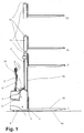
- Figure 1 shows schematically a stacker 1 according to the invention with four different stroke positions of the load receiving means 2.
- the stacker 1 is divided into a drive part 3 and a load part 4.
- drive motor for the steerable drive wheel 4 and a control unit 5 for driving the drive and lifting functions housed.
- a arranged in the drive part 2 battery to power the high-lift truck 1 serves.
- the vehicle 1 is steered by means of a drawbar 6, wherein operating elements 8 for controlling the functions of the industrial truck 1 are mounted on the tiller head 7.
- the load part 3 of the truck 1 comprises a mast 9 on which a liftable load-receiving means 2 is guided.
- the mast 9 is composed of an outer, fixed part, the so-called stationary mast 10 and an inner part which can be extended upward, the so-called mast 11.
- the load-carrying means 2 is fork-shaped and located in the position I, in for example, pallets or lattice boxes can be picked up from the ground.
- the load-receiving means 2 is moved upwards on the mast 9 via a hydraulic cylinder, not shown here, and thus finally reaches position II.
- the mast 11 remains in its position during this process. If greater lifting heights are to be achieved, the vertical movement of the load receiving means 2 is generated by the extension of the traveling mast 11, while the load receiving means 2 does not change its position relative to the traveling mast 11. In this way, the position III is achieved on continuation of the lifting movement and finally in the maximum extended position IV.
- a radar unit 12 is attached as means for determining the distance of obstacles located above the lifting device.
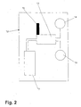
- the basic structure of this radar unit 12 is shown schematically in FIG.
- An electronic control unit 13 is in operative connection with a transmitting unit 14 for transmitting radar waves.
- the radar waves emitted by the transmitting unit 14 are reflected by an obstacle and detected by a receiving unit 15.
- the distance to an obstacle is calculated from the transit time from the emission of the signal to the arrival of the echo.
- a transmitting device 16 connected to the control unit 13 sends this information to the control unit 5 of the industrial truck.
- a battery 17 is used to power the radar device 12.
- the radar unit 12 is attached to the upper end of the traveling mast 11.
- An attachment as far above the truck 1 is advantageous because then no components of the truck 1 protrude into the measuring range.
- the attachment to the mast 11 is advantageous because on the one hand the risk of damage to the radar unit 12 during operation is low and the radar unit 12 is still easily accessible, for example, for maintenance.
- the mast 11 is extended to achieve greater heights, whereby the distance between an obstacle, such as a building ceiling, and the radar unit 12 is reduced.
- the detected distance values are transmitted in the above-described manner to the control unit 5 of the truck 1.
- the control unit 5 transmits the data to a display device 18, which indicates the distance of the uppermost part of the truck 1, which is the radar unit 12 in the embodiment shown, to the obstacle.
- a display device 18 indicates the distance of the uppermost part of the truck 1, which is the radar unit 12 in the embodiment shown, to the obstacle.
- different colored lighting elements are also provided, which are activated as a function of the distance to an obstacle. If there is no obstacle within the lifting height of the truck 1, no lighting element is active, there is an obstacle within the possible lifting height, but still a sufficient safety distance is maintained with the highest possible load, a green light element is active. As a result, the operator recognizes at a glance that the risk of a collision continues as the load is lifted further.
- a yellow indicator element lights up If the load-carrying means 2 and thus the traveling mast 11 reaches a lifting height at which, in addition to an appropriate safety area, the highest expected load would collide with the obstacle, a yellow indicator element lights up. Now the operator knows that they have to be very careful, because depending on the height of the load a collision is possible. If the radar unit 12, and thus the uppermost point of the industrial truck 1, comes into an area in which the distance to an obstacle is less than a suitably selected safety area when the lifting device 2 is lifted further, a red indicator element lights up. The operator now knows that a collision of the traveling mast 11 of the industrial truck 1 with the obstacle is imminent. Immediately before a collision of the radar unit 12 as the uppermost point of the truck 1 with the obstacle of the lifting drive is disabled and the red indicator flashes.
- the security areas are each selected so that with a reasonable reaction time of the operator still a safe stopping of the lifting device is possible before the actually assigned to the mecanicmeni area is reached.
- means for detecting the height of the load are present.
- This can be both measuring devices that determine the height of the load, for example, also via non-contact methods, as well Devices by means of which the height of the load can be entered by the operator or, in particular in standardized load-handling devices such as lattice boxes, can be detected automatically.
- the specification of the load height by the operator can be made, for example, via a keyboard, but also by a scanner device that reads coded information on the load or in freight documents.
- the control device 5 of the distance value which is detected by the radar device 12
- the difference between the height of the load and subtracts the distance between the highest point of the truck and the upper edge 18 of the prong 19 of the lifting device 2 of this distance value is the distance between the upper edge of the load and the obstacle and can therefore be processed in the manner described above, that is represented in a display unit or used to limit the lifting height.
- a location other than that shown for the means for detecting an obstacle for example the driver's safety roof of a counterbalanced forklift or of a reach truck.
- the mounting location is also decisive for the choice of the power supply and the information transmission between the device for detecting an obstacle and the control unit of the truck.
- a stand-alone power supply and wireless transmission of the distance information is advantageous because it significantly reduces the cabling. Even with retrofittable devices for detecting an obstacle, such a solution is advantageous.
- a connection via cable for the transmission of energy and / or information is very secure and requires little maintenance.
- the transmitting unit 14 and the receiving unit 15 for the radar signal as well as the electronic control unit 13 used for the evaluation can be mounted at different locations of the industrial truck 1.
- Such means are in particular also advantageous when working in shelves or at a loading dock where too much lowering of the load handling device may cause damage to the truck or the ramp or the rack.
- the display device may differ in type and attachment of the described embodiment, for example, by an acoustic warning is provided or a visual display in the form of a scale.
Landscapes
- Engineering & Computer Science (AREA)
- Structural Engineering (AREA)
- Transportation (AREA)
- Life Sciences & Earth Sciences (AREA)
- Geology (AREA)
- Mechanical Engineering (AREA)
- Civil Engineering (AREA)
- Forklifts And Lifting Vehicles (AREA)
Abstract
Description
- Die Erfindung betrifft ein Flurförderzeug mit einem anhebbaren Lastaufnahmemittel. Derartige Flurförderzeuge werden verwendet, um im innerbetrieblichen Warentransport Lasten sowohl bodennah als auch in größeren Höhen aufnehmen beziehungsweise absetzen zu können. Da Gebäude von Industriebetrieben häufig erstellt wurden, bevor derartige Flurförderzeuge zum Einsatz kamen, sind bisweilen in einzelnen Bereichen Deckenhöhen und Durchfahrtshöhen unter Hindernissen niedriger als die maximale Hubhöhe eines Flurförderzeugs. Wird eine solche Situation von der Bedienperson des Flurförderzeugs nicht rechtzeitig bemerkt und die in diesen Bereichen maximal zulässige Hubhöhe überschritten, kann es zu schweren Beschädigungen des Ladegutes oder des Flurförderzeugs kommen. Um dies zu vermeiden, kann die maximale Hubhöhe auf ein ungefährliches Maß begrenzt werden, doch ist damit eine Ausnutzung der größeren Höhe anderer Gebäudeteile für Lagerzwecke nicht mehr möglich.
- Wenn eine Bedienperson die Gefahr einer Berührung mit einem Hindernis erkannt hat, ist es dennoch häufig schwierig, insbesondere bei großen Hubhöhen, den Abstand der Last oder des Hubmastes von einem Hindernis richtig einzuschätzen. Die Bedienperson wird darum in diesen Bereichen mit besonderer Sorgfalt arbeiten und dementsprechend eine langsame Hubgeschwindigkeit wählen, so dass die Produktivität des Flurförderzeugs deutlich sinkt.
- Der Erfindung liegt daher die Aufgabe zugrunde, ein Flurförderzeug mit einem anhebbaren Lastaufnahmemittel zu schaffen, bei dem die Betriebssicherheit des Flurförderzeugs verbessert und die Gefahr einer Beschädigung von Ladegut und/oder Flurförderzeug insbesondere bei besonders hohen Hubhöhen ausgeschlossen wird.
- Diese Aufgabe wird erfindungsgemäß dadurch gelöst, dass Mittel zur Abstandsbestimmung von oberhalb und/oder unterhalb des Lastaufnahmemittels befindlichen Hindernissen zu Teilen des Flurförderzeugs und/oder einer auf dem Lastaufnahmemittel befindlichen Last vorgesehen sind. Wenn der Abstand zwischen Hindernissen und einer Last beziehungsweise dem Flurförderzeug bekannt ist, können Maßnahmen getroffen werden, die geeignet sind, eine Kollision verhindern. Aufgrund dieser Maßnahmen muss die Bedienperson weniger Aufmerksamkeit auf die Vermeidung von Kollisionen richten und kann dadurch ermüdungsfreier und schneller arbeiten. Als Hindernisse oberhalb beziehungsweise unterhalb des Lastaufnahmemittels werden Hindernisse angesehen, die sich in einem Bereich befinden, der oberhalb beziehungsweise unterhalb der durch das Lastaufnahmemittel, insbesondere die Zinken eines gabelförmigen Lastaufnahmemittels definierten annähernd waagerechten Ebene liegt und parallel zu dieser Ebene eine Ausdehnung besitzt, die maximal in etwa der Ausdehnung der größten zu erwartenden Last zuzüglich eines Sicherheitsabstands von einigen Dezimetern entspricht.
- Es ist besonders vorteilhaft, wenn die Mittel zur Abstandsbestimmung einem berührungslosen Wirkprinzip folgen. Eine berührungslose Abstandsbestimmung ist auch über größere Entfernungen möglich. Indem Berührung vermieden wird, besteht keine Gefahr einer Beschädigung sowohl des Messmittels als auch des zu erfassenden Hindernisses.
- In einer besonders vorteilhaften Ausgestaltung der Erfindung umfassen die Mittel zur Abstandsbestimmung mindestens eine Sendeeinheit und/oder mindestens eine Empfangseinheit für elektromagnetische Strahlung, vorzugsweise mit einer Wellenlänge im Bereich von einigen Zentimetern. Anstandsmessung durch elektromagnetische Strahlung ist besonders einfach und zuverlässig durchführbar, beispielsweise über Laufzeitmessungen. Gegenüber Verfahren mit sichtbarem Licht oder Infrarotstrahlung bietet die Radartechnik, die in einem Wellenlängenbereich von einigen Zentimetern arbeitet, Vorteile, da diese gegenüber Störeinflüssen, wie beispielsweise Verschmutzungen in der Luft, unempfindlich ist.
- In einer weiteren zweckmäßigen Ausgestaltung der Erfindung umfassen die Mittel zur Abstandsbestimmung mindestens eine Sendeeinheit und/oder mindestens eine Empfangseinheit für Schallwellen, vorzugsweise mit einer Wellenlänge außerhalb des menschlichen Hörbereichs. Schallwellen bieten über Laufzeitmessungen eine einfache Möglichkeit zur Entfernungsmessung. Es entsteht keine möglicherweise störende elektromagnetische Strahlung. Wird eine Wellenlänge außerhalb des menschlichen Hörbereichs gewählt, werden Störungen der Bedienperson oder umstehender Personen vermieden.
- Es ist vorteilhaft, wenn die Mittel zur Abstandsbestimmung im Bereich eines Hubmastes, vorzugsweise am höchsten Punkt des Hubmastes und/oder am Lastaufnahmemittel, angeordnet sind. Dadurch sind die zu messenden Abstände kurz und Störungen des Messwegs, beispielsweise durch auf den Sende- oder Empfangseinheiten abgelegte Gegenstände werden vermieden. Werden die Mittel zur Abstandsbestimmung an einem beweglichen Teil der Hubvorrichtung, wie beispielsweise dem Lastaufnahmemittel, angebracht, wird die Veränderung des Abstandes direkt erfasst.
- In einer besonders vorteilhaften Ausgestaltung der Erfindung stehen die Mittel zur Abstandsbestimmung mit einer elektrischen Steuereinheit des Flurförderzeugs vorzugsweise mittels drahtloser Übertragungsmittel in Wirkverbindung. Dadurch wird die Information über den Abstand zwischen einem Hindernis und Teilen des Flurförderzeugs oder der Last für die Steuereinheit verfügbar und kann zu Steuerungszwecken verwendet werden
- Es ist von Vorteil, wenn mittels der elektrischen Steuereinheit eine Begrenzung der Hubhöhe des Lastaufnahmemittels auf einen Wert vornehmbar ist, der eine Kollision zwischen oberhalb und/oder unterhalb des Lastaufnahmemittels befindlichen Hindernissen und Teilen des Flurförderzeugs und/oder der Last ausschließt. Da der Abstand zum Hindernis erfasst und in der Steuereinheit bekannt ist, wird vor Erreichen einer Hubhöhe, die zu Beschädigungen am Flurförderzeug oder der Last führen kann, das Lastaufnahmemittel gestoppt. Die Bedienperson muss sich nicht auf die Vermeidung einer möglichen Kollision zwischen Hindernis und Last/Flurförderzeug konzentrieren und kann die Hubvorgänge zügig durchführen.
- Es ist besonders zweckmäßig, wenn mindestens eine Anzeigevorrichtung zur Signalisierung des Abstandes zwischen oberhalb und/oder unterhalb des Lastaufnahmemittels befindlichen Hindernissen und/oder der Last vorgesehen ist. Dadurch wird die Bedienperson auf eine mögliche Gefahr aufmerksam gemacht und kann diese besonders gut einschätzen. Sie kann zügig und dennoch umsichtig die Hubfunktionen bedienen.
- Zweckmäßigerweise umfassen die Mittel zur Abstandsbestimmung mindestens eine von der Energieversorgung des Flurförderzeugs unabhängige Vorrichtung zur Energieversorgung, vorzugsweise eine Batterie. Dadurch tritt kein zusätzlicher Verkabelungsaufwand am Flurförderzeug auf, der insbesondere bei einer Anbringung an beweglichen Teilen sehr hoch ist.
- Weiterhin ist es zweckmäßig, wenn Mittel zur Erfassung der Höhe der Last vorgesehen sind. Damit kann festgestellt werden, ob die Last beim Anheben über das höchste Teil des Flurförderzeugs hinausragt. In diesem Fall ist der Abstand zwischen dem höchsten Teil der Last und dem niedrigsten Teil des Hindernisses maßgebend für die Gefahr einer Kollision.
- Die Aufgabe wird weiterhin dadurch gelöst, dass eine Vorrichtung zur Abstandsbestimmung von oberhalb und/oder unterhalb des Lastaufnahmemittels befindlichen Hindernissen zu Teilen des Flurförderzeugs und/oder einer auf dem Lastaufnahmemittel befindlichen Last ausgebildet gemäß einem der vorhergehenden Ansprüche bei vorhandenen Flurförderzeugen nachrüstbar ist. Indem vorhandene Flurförderzeug mit einer erfindungsgemäßen Vorrichtung nachgerüstet werden, erfüllen auch diese einen höheren Sicherheitsstandard. Es wird vermieden, dass bei Einsatz verschiedener Flurförderzeuge in einem Betrieb unterschiedliche Bedienung und unterschiedliche Sicherheitsstandards gegeben sind.
- Weitere Vorteile und Einzelheiten der Erfindung werden anhand der in den schematischen Figuren dargestellten Ausführungsbeispiele näher erläutert. Dabei zeigt
- Figur 1
- die Seitenansicht eines erfindungsgemäßen Hochhubwagens mit vier verschiedenen Hubpositionen des Lastaufnahmemittels.
- Figur 2
- den schematischen Aufbau einer Vorrichtung zur Abstandsbestimmung von oberhalb und/oder unterhalb des Lastaufnahmemittels befindlichen Hindernissen zu Teilen des Flurförderzeugs und/oder einer auf dem Lastaufnahmemittel befindlichen Last.
- Figur 1 zeigt schematisch einen erfindungsgemäßen Hochhubwagen 1 mit vier verschiedenen Hubpositionen des Lastaufnahmemittels 2. Der Hochhubwagen 1 gliedert sich in einen Antriebsteil 3 und einen Lastteil 4. Im Antriebsteil 2 ist der hier nicht dargestellte Antriebsmotor für das lenkbare Antriebsrad 4 und eine Steuerungseinheit 5 zur Ansteuerung der Antriebs- und Hubfunktionen untergebracht. Nicht dargestellt ist eine im Antriebsteil 2 angeordnete Batterie, die zur Energieversorgung des Hochhubwagens 1 dient. Gelenkt wird das Fahrzeug 1 über eine Deichsel 6, wobei am Deichselkopf 7 Bedienelemente 8 zur Steuerung der Funktionen des Flurförderzeugs 1 angebracht sind.
Der Lastteil 3 des Flurförderzeugs 1 umfasst ein Hubgerüst 9 an dem ein anhebbares Lastaufnahmemittel 2 geführt ist. Das Hubgerüst 9 setzt sich aus einem äußeren, feststehenden Teil, dem so genannten Standmast 10 und einem inneren Teil zusammen, der nach oben ausfahrbar ist, dem so genannten Fahrmast 11. Das Lastaufnahmemittel 2 ist gabelförmig ausgeführt und befindet sich in der Position I, in der beispielsweise Paletten oder Gitterboxen vom Boden aufgenommen werden können. Um die Last anzuheben, wird das Lastaufnahmemittel 2 über einen hier nicht dargestellten Hydraulikzylinder am Hubgerüst 9 nach oben bewegt und erreicht so schließlich die Position II. Der Fahrmast 11 bleibt bei diesem Vorgang in seiner Position. Sollen größere Hubhöhen erreicht werden, wird die Vertikalbewegung des Lastaufnahmemittels 2 durch das Ausfahren des Fahrmasts 11 erzeugt, während das Lastaufnahmemittel 2 gegenüber dem Fahrmast 11 seine Position nicht mehr ändert. Auf diese Weise wird bei Fortführung der Hubbewegung die Position III und schließlich in maximal ausgefahrenem Zustand die Position IV erreicht. - Im oberen Bereich des Fahrmasts 11 ist als Mittel zur Abstandsbestimmung von oberhalb des Lastaufnahmemittels befindlichen Hindernissen eine Radareinheit 12 angebracht. Der prinzipielle Aufbau dieser Radareinheit 12 ist schematisch in Figur 2 gezeigt. Eine elektronische Steuerungseinheit 13 steht mit einer Sendeeinheit 14 zur Aussendung von Radarwellen in Wirkverbindung. Die von der Sendeeinheit 14 ausgesandten Radarwellen werden von einem Hindernis reflektiert und von einer Empfangseinheit 15 erfasst. In der elektronischen Steuerungseinheit 13 wird aus der Laufzeit vom Aussenden des Signals bis zum Eintreffen des Echos der Abstand zu einem Hindernis berechnet. Eine an die Steuerungseinheit 13 angeschlossene Sendevorrichtung 16 sendet diese Information an die Steuerungseinheit 5 des Flurförderzeugs. Zur Energieversorgung der Radarvorrichtung 12 dient eine Batterie 17.
- Die Radareinheit 12 ist am oberen Ende des Fahrmasts 11 angebracht. Eine Anbringung möglichst weit oben am Flurförderzeug 1 ist vorteilhaft, da dann keine Bauteile des Flurförderzeugs 1 in den Messbereich ragen. Insbesondere bei Hochhubwagen 1, wo kein Fahrerschutzdach vorhanden ist, ist die Anbringung am Fahrmast 11 vorteilhaft, da so einerseits die Gefahr einer Beschädigung der Radareinheit 12 im Betrieb gering ist und die Radareinheit 12 dennoch gut erreichbar ist, beispielsweise für Wartungsarbeiten. Der Fahrmast 11 wird zum Erreichen größerer Hubhöhen ausgefahren, wodurch sich der Abstand zwischen einem Hindernis, beispielsweise einer Gebäudedecke, und der Radareinheit 12 verringert. Die erfassten Abstandswerte werden in der oben geschilderten Weise an die Steuerungseinheit 5 des Flurförderzeugs 1 übertragen. Die Steuerungseinheit 5 übermittelt die Daten an eine Anzeigevorrichtung 18, die den Abstand des obersten Teils des Flurförderzeugs 1, welches im gezeigten Ausführungsbeispiel die Radareinheit 12 ist, zu dem Hindernis anzeigt. Neben einer Zahlenangabe sind zusätzlich verschiedenfarbige Leuchtelemente vorgesehen, die in Abhängigkeit vom Abstand zu einem Hindernis aktiviert werden. Ist kein Hindernis innerhalb der Hubhöhe des Flurförderzeugs 1, ist kein Leuchtelement aktiv, befindet sich ein Hindernis innerhalb der möglichen Hubhöhe, zu dem jedoch noch ein ausreichender Sicherheitsabstand auch mit der höchstmöglichen Last eingehalten wird, ist ein grünes Leuchtelement aktiv. Dadurch erkennt die Bedienperson mit einem Blick, dass bei weiterem Anheben der Last die Gefahr einer Kollision besteht. Erreicht das Lastaufnahmemittel 2 und damit der Fahrmast 11 eine Hubhöhe, bei der zuzüglich eines angemessenen Sicherheitsbereichs die höchste zu erwartende Last mit dem Hindernis kollidieren würde, leuchtet ein gelbes Anzeigeelement auf. Nun weiß die Bedienperson, dass sie besonders umsichtig vorgehen muss, da je nach Höhe der Last eine Kollision möglich ist. Wenn bei weiterem Anheben des Lastaufnahmemittels 2 die Radareinheit 12 und damit der oberste Punkt des Flurförderzeugs 1 in einen Bereich gelangt, in dem der Abstand zu einem Hindernis kleiner ist als ein geeignet gewählter Sicherheitsbereich, leuchtet ein rotes Anzeigeelement auf. Die Bedienperson weiß nun, dass eine Kollision des Fahrmasts 11 des Flurförderzeugs 1 mit dem Hindernis unmittelbar bevorsteht. Unmittelbar vor einer Kollision der Radareinheit 12 als oberster Punkt des Flurförderzeugs 1 mit dem Hindernis wird der Hubantrieb deaktiviert und das rote Anzeigelement blinkt. Dadurch wird eine Kollision vermieden und die Bedienperson weiß, dass nur noch eine Abwärtsbewegung des Lastaufnahmemittels möglich ist. Die Sicherheitsbereiche sind jeweils so gewählt, dass bei einer angemessenen Reaktionszeit der Bedienperson noch ein sicheres Abstoppen des Lastaufnahmemittels möglich ist, bevor der eigentlich dem Anzeigenelemeni zugeordnete Bereich erreicht wird.
- In einer weiteren, hier nicht gezeigten Ausführungsform sind Mittel zur Erfassung der Höhe der Last vorhanden. Dies können sowohl Messvorrichtungen sein, die die Höhe der Last beispielsweise ebenfalls über berührungslose Verfahren, ermitteln, als auch Vorrichtungen, mittels derer die Höhe der Last durch die Bedienperson eingegeben werden kann oder, insbesondere bei standardisierten Lastaufnahmevorrichtungen wie Gitterboxen, automatisch erfasst werden kann. Die Vorgabe der Lasthöhe durch die Bedienperson kann beispielsweise über eine Tastatur, aber auch durch eine Scannervorrichtung, die kodierte Informationen auf der Last oder in Frachtpapieren ausliest, vorgenommen werden. Ist die Höhe der Last größer als der Abstand zwischen der Oberkante 18 einer Zinke 19 des Lastaufnahmemittels 2 und der Oberkante des Flurförderzeugs 1, so wird in der Steuerungsvorrichtung 5 vom Abstandswert, der von der Radareinrichtung 12 erfasst wird, die Differenz zwischen der Höhe der Last und dem Abstand zwischen dem höchsten Punkt des Flurförderzeugs und der Oberkante 18 der Zinke 19 des Lastaufnahmemittels 2 von diesem Abstandswert subtrahiert. Dieser Wert ist der Abstand zwischen der Oberkante der Last und dem Hindernis und kann daher in der oben geschilderten Weise verarbeitet, also in einer Anzeigeeinheit dargestellt oder zur Begrenzung der Hubhöhe verwendet werden.
- Selbstverständlich sind weitere Ausführungsformen denkbar, beispielsweise die Verwendung anderer Vorrichtungen um Hindernisse zu erfassen. Hier sind insbesondere Vorrichtungen, die Verfahren, die auf der Aussendung eines Ultraschall-Signals beruhen, zu nennen. Auch kann beispielsweise ein einzelnes Bauteil sowohl als Sendeeinheit 14 wie auch als Empfangseinheit 15 für die zur Messung verwendete Strahlung verwendet werden, indem ein pulsweise abgeschicktes Signal verwendet wird.
- Je nach Art des Flurförderzeugs 1 kann auch ein anderer als der gezeigte Anbringungsort für die Mittel zur Erfassung eines Hindernisses vorteilhaft sein, beispielsweise das Fahrerschutzdach eines Gegengewichtsgabelstaplers oder eines Schubmaststaplers. Insbesondere der Anbringungsort ist auch entscheiden für die Wahl der Energieversorgung und der Informationsübertragung zwischen der Vorrichtung zur Erfassung eines Hindernisses und der Steuerungseinheit des Flurförderzeugs. Bei einer Anbringung an beweglichen Teilen des Hubgerüsts, wie im oben gezeigten Ausführungsbeispiel, ist eine eigenständige Energieversorgung sowie eine drahtlose Übertragung der Abstandsinformation vorteilhaft, weil dadurch der Verkabelungsaufwand deutlich verringert wird. Auch bei nachrüstbaren Vorrichtungen zur Erfassung eines Hindernisses ist eine derartige Lösung vorteilhaft. Eine Anbindung über Kabel zur Übertragung von Energie und/oder Informationen ist dagegen sehr sicher und erfordert nur geringen Wartungsaufwand. Insbesondere bei nachrüstbaren Vorrichtungen zur Erfassung eines Hindernisses kann auch eine Anzeigevorrichtung integriert sein, so dass keinerlei Eingriffe am Flurförderzeug nötig sind. Umgekehrt können bei fest eingebauten Mitteln zur Erfassung eines Hindernisses die Sendeeinheit 14 und die Empfangseinheit 15 für das Radarsignal ebenso wie die zur Auswertung verwendete elektronische Steuerungseinheit 13 an verschiedenen Orten des Flurförderzeugs 1 angebracht sein.
- Es können auch Mittel zur Abstandsbestimmung zu Hindernissen unterhalb des Lastaufnahmemittels vorgesehen sein, beispielsweise bei Flurförderzeugen, bei denen das Lastaufnahmemittel unterhalb des normalen Bodenniveaus abgesenkt werden kann oder wenn im Bodenbereich Hindernisse, wie beispielsweise Schwellen oder Absätze, vorhanden sind. Derartige Mittel sind ist insbesondere auch vorteilhaft bei Arbeiten in Regalen oder an einer Laderampe, bei denen ein zu weites Absenken des Lastaufnahmemittels Beschädigungen am Flurförderzeug oder der Rampe beziehungsweise dem Regal verursachen kann.
- Auch die Anzeigevorrichtung kann sich nach Art und Anbringung von der beschriebenen Ausführungsform unterscheiden, beispielsweise, indem eine akustische Warnung vorgesehen ist oder eine optische Anzeige in Form einer Skala.
- Neben oder anstelle einer Deaktivierung des Hubantriebs bei Unterschreiten eines kritischen Abstandes zwischen der Last und/oder dem Hubgerüst und einem Hindernis sind auch weitere Maßnahmen zur Erhöhung der Sicherheit denkbar, beispielsweise eine Reduzierung der Hubgeschwindigkeit bei Unterschreiten eines vorgegebenen Abstandswertes.
Claims (11)
- Flurförderzeug (1) mit einem anhebbaren Lastaufnahmemittel (2), dadurch gekennzeichnet, dass Mittel (12) zur Abstandsbestimmung von oberhalb und/oder unterhalb des Lastaufnahmemittels (2) befindlichen Hindernissen zu Teilen des Flurförderzeugs (1) und/oder einer auf dem Lastaufnahmemittel (2) befindlichen Last vorgesehen sind.
- Flurtörderzeug (1) nach Anspruch 1, dadurch gekennzeichnet, dass die Mittel (12) zur Abstandsbestimmung einem berührungslosen Wirkprinzip folgen.
- Flurförderzeug (1) nach Anspruch 1 oder 2, dadurch gekennzeichnet, dass die Mittel (12) zur Abstandsbestimmung mindestens eine Sendeeinheit (14) und/oder mindestens eine Empfangseinheit (15) für elektromagnetische Strahlung, vorzugsweise mit einer Wellenlänge im Bereich von einigen Zentimetern, umfassen.
- Flurförderzeug (1) nach einem der Ansprüche 1 bis 3, dadurch gekennzeichnet, dass die Mittel (12) zur Abstandsbestimmung mindestens eine Sendeeinheit und/oder mindestens eine Empfangseinheit für Schallwellen, vorzugsweise mit einer Wellenlänge außerhalb des menschlichen Hörbereichs, umfassen.
- Flurförderzeug (1) nach einem der Ansprüche 1 bis 4, dadurch gekennzeichnet, dass die Mittel (12) zur Abstandsbestimmung im Bereich eines Hubmastes (9), vorzugsweise am höchsten Punkt des Hubmastes (9) und/oder am Lastaufnahmemittel (2), angeordnet sind.
- Flurförderzeug (1) nach einem der Ansprüche 1 bis 5, dadurch gekennzeichnet, dass die Mittel (12) zur Abstandsbestimmung mit einer elektrischen Steuereinheit (5) des Flurförderzeugs (1) vorzugsweise mittels drahtloser Übertragungsmittel in Wirkverbindung stehen.
- Flurförderzeug (1) nach einem der Ansprüche 1 bis 6, dadurch gekennzeichnet, dass mittels der elektrischen Steuereinheit eine Begrenzung der Hubhöhe des Lastaufnahmemittels auf einen Wert vomehmbar ist, der eine Kollision zwischen oberhalb und/oder unterhalb des Lastaufnahmemittels () befindlichen Hindernissen und Teilen des Flurförderzeugs und/oder der Last ausschließt.
- Flurförderzeug (1) nach einem der Ansprüche 1 bis 7, dadurch gekennzeichnet, dass mindestens eine Anzeigevorrichtung (18) zur Signalisierung des Abstandes zwischen oberhalb und/oder unterhalb des Lastaufnahmemittels (2) befindlichen Hindernissen und /oder der Last vorgesehen ist.
- Flurförderzeug (1) nach einem der Ansprüche 1 bis 8, dadurch gekennzeichnet, dass die Mittel (12) zur Abstandsbestimmung mindestens eine von der Energieversorgung des Flurförderzeugs (1) unabhängige Vorrichtung zur Energieversorgung, vorzugsweise eine Batterie (17), umfassen.
- Flurförderzeug (1) nach einem der Ansprüche 1 bis 9, dadurch gekennzeichnet, dass Mittel zur Erfassung der Höhe der Last vorgesehen sind.
- Vorrichtung (12) zur Abstandsbestimmung von oberhalb und/oder unterhalb des Lastaufnahmemittels (2) befindlichen Hindernissen zu Teilen des Flurförderzeugs (1) und/oder einer auf dem Lastaufnahmemittel (2) befindlichen Last ausgebildet gemäß einem der vorhergehenden Ansprüche, dadurch gekennzeichnet, dass die Vorrichtung (12) bei vorhandenen Flurförderzeugen (1) nachrüstbar ist.
Applications Claiming Priority (1)
| Application Number | Priority Date | Filing Date | Title |
|---|---|---|---|
| DE200410059700 DE102004059700A1 (de) | 2004-12-10 | 2004-12-10 | Flurförderzeug mit einem anhebbaren Lastaufnahmemittel |
Publications (2)
| Publication Number | Publication Date |
|---|---|
| EP1669319A1 true EP1669319A1 (de) | 2006-06-14 |
| EP1669319B1 EP1669319B1 (de) | 2015-07-29 |
Family
ID=36096117
Family Applications (1)
| Application Number | Title | Priority Date | Filing Date |
|---|---|---|---|
| EP05026402.7A Expired - Lifetime EP1669319B1 (de) | 2004-12-10 | 2005-12-02 | Flurförderzeug mit einem anhebbaren Lastaufnahmemittel |
Country Status (2)
| Country | Link |
|---|---|
| EP (1) | EP1669319B1 (de) |
| DE (1) | DE102004059700A1 (de) |
Cited By (1)
| Publication number | Priority date | Publication date | Assignee | Title |
|---|---|---|---|---|
| EP2567933A1 (de) * | 2011-09-07 | 2013-03-13 | Jungheinrich Aktiengesellschaft | Gewerbliches Fahrzeug mit nach oben gerichteten sensierendem Radarsensor |
Citations (3)
| Publication number | Priority date | Publication date | Assignee | Title |
|---|---|---|---|---|
| EP0846649A1 (de) * | 1996-12-06 | 1998-06-10 | Mitsubishi Heavy Industries, Ltd. | Kollisionsvermeidungsvorrichtung eines Krans |
| US5906648A (en) | 1996-07-29 | 1999-05-25 | Erim International, Inc. | Collision avoidance system for vehicles having elevated apparatus |
| FR2836468A1 (fr) * | 2002-02-28 | 2003-08-29 | Pinguely Haulotte | Nacelle elevatrice a securite amelioree |
-
2004
- 2004-12-10 DE DE200410059700 patent/DE102004059700A1/de not_active Withdrawn
-
2005
- 2005-12-02 EP EP05026402.7A patent/EP1669319B1/de not_active Expired - Lifetime
Patent Citations (3)
| Publication number | Priority date | Publication date | Assignee | Title |
|---|---|---|---|---|
| US5906648A (en) | 1996-07-29 | 1999-05-25 | Erim International, Inc. | Collision avoidance system for vehicles having elevated apparatus |
| EP0846649A1 (de) * | 1996-12-06 | 1998-06-10 | Mitsubishi Heavy Industries, Ltd. | Kollisionsvermeidungsvorrichtung eines Krans |
| FR2836468A1 (fr) * | 2002-02-28 | 2003-08-29 | Pinguely Haulotte | Nacelle elevatrice a securite amelioree |
Cited By (1)
| Publication number | Priority date | Publication date | Assignee | Title |
|---|---|---|---|---|
| EP2567933A1 (de) * | 2011-09-07 | 2013-03-13 | Jungheinrich Aktiengesellschaft | Gewerbliches Fahrzeug mit nach oben gerichteten sensierendem Radarsensor |
Also Published As
| Publication number | Publication date |
|---|---|
| DE102004059700A1 (de) | 2006-06-14 |
| EP1669319B1 (de) | 2015-07-29 |
Similar Documents
| Publication | Publication Date | Title |
|---|---|---|
| EP1834922B1 (de) | Flurförderzeug mit einem Hubmast | |
| EP3875990B1 (de) | System zur inspektion eines lagers | |
| EP3241801B1 (de) | Verfahren zur kollisionsüberwachung bei einem flurförderzeug | |
| EP1886966B1 (de) | Flurförderzeug mit einem anhebbaren Lastaufnahmemittel | |
| DE102008054085B4 (de) | Flurförderzeug | |
| EP3114050A1 (de) | Kanalfahrzeug, regallager mit einem kanalfahrzeug sowie verfahren zur steuerung eines kanalfahrzeugs | |
| DE102018207202B4 (de) | Fahrerloses Transportfahrzeug und Verfahren zum Betreiben eines fahrerlosen Transportfahrzeugs | |
| EP2468678A1 (de) | Flurförderzeug mit einem Sensor zur Erfassung einer räumlichen Umgebung und Verfahren zum Betreiben eines solchen Flurförderzeugs | |
| DE10323641A1 (de) | Bewegliche Sensoreinrichtung am Lastmittel eines Gabelstaplers | |
| EP3365194B1 (de) | Laderampensicherungseinrichtung | |
| DE202012004038U1 (de) | Flurförderzeug mit mindestens einem Abstandssensor | |
| DE202014102274U1 (de) | Folienerkennung und Palettentyperkennung mittels Kanalfahrzeug in einem Kanalregallager | |
| DE69716016T2 (de) | Kollisionsvermeidungsvorrichtung für einen Kran | |
| EP3722912A1 (de) | Verfahren zur kollisionsvermeidung bei einem fahrerlosen transportfahrzeug und entsprechendes fahrerloses transportfahrzeug | |
| EP4439218A1 (de) | Fahrerloses transportfahrzeug | |
| EP1669319B1 (de) | Flurförderzeug mit einem anhebbaren Lastaufnahmemittel | |
| EP3925926B1 (de) | Flurförderzeug | |
| DE102022206053B3 (de) | Vorrichtung zur Hinderniserkennung an einem Fahrzeug mit Hubvorrichtung und Verfahren zum Betreiben einer solchen Vorrichtung | |
| WO2022218743A1 (de) | Verfahren zur zustandsüberwachung eines hubwagens eines staplerfahrzeugs | |
| DE102009006175A1 (de) | Flurförderzeug mit Beleuchtungseinrichtung und Verfahren zum Betrieb des Flurförderzeugs | |
| EP1669320B1 (de) | Flurförderzeug mit einem höhenveränderlichen Lastaufnahmemittel | |
| DE102017220359A1 (de) | Flurförderzeug mit an heb- und senkbaren Lastaufnahmemitteln angeordneten Kameras | |
| EP2698337B9 (de) | Verfahren zum Betrieb eines Flurförderzeugs | |
| DE102013112016B4 (de) | Flurförderzeug mit einem Hubhöhenassistenzsystem | |
| EP1293472A2 (de) | Flurförderzeug mit Sicherheitseinrichtung |
Legal Events
| Date | Code | Title | Description |
|---|---|---|---|
| PUAI | Public reference made under article 153(3) epc to a published international application that has entered the european phase |
Free format text: ORIGINAL CODE: 0009012 |
|
| AK | Designated contracting states |
Kind code of ref document: A1 Designated state(s): AT BE BG CH CY CZ DE DK EE ES FI FR GB GR HU IE IS IT LI LT LU LV MC NL PL PT RO SE SI SK TR |
|
| AX | Request for extension of the european patent |
Extension state: AL BA HR MK YU |
|
| 17P | Request for examination filed |
Effective date: 20061114 |
|
| 17Q | First examination report despatched |
Effective date: 20061219 |
|
| AKX | Designation fees paid |
Designated state(s): AT BE BG CH CY CZ DE DK EE ES FI FR GB GR HU IE IS IT LI LT LU LV MC NL PL PT RO SE SI SK TR |
|
| RAP1 | Party data changed (applicant data changed or rights of an application transferred) |
Owner name: STILL SAS |
|
| RAP1 | Party data changed (applicant data changed or rights of an application transferred) |
Owner name: OM CARRELLI ELEVATORI S.P.A. |
|
| GRAP | Despatch of communication of intention to grant a patent |
Free format text: ORIGINAL CODE: EPIDOSNIGR1 |
|
| INTG | Intention to grant announced |
Effective date: 20150415 |
|
| GRAP | Despatch of communication of intention to grant a patent |
Free format text: ORIGINAL CODE: EPIDOSNIGR1 |
|
| INTG | Intention to grant announced |
Effective date: 20150522 |
|
| GRAS | Grant fee paid |
Free format text: ORIGINAL CODE: EPIDOSNIGR3 |
|
| GRAA | (expected) grant |
Free format text: ORIGINAL CODE: 0009210 |
|
| AK | Designated contracting states |
Kind code of ref document: B1 Designated state(s): AT BE BG CH CY CZ DE DK EE ES FI FR GB GR HU IE IS IT LI LT LU LV MC NL PL PT RO SE SI SK TR |
|
| REG | Reference to a national code |
Ref country code: GB Ref legal event code: FG4D Free format text: NOT ENGLISH |
|
| REG | Reference to a national code |
Ref country code: CH Ref legal event code: EP |
|
| REG | Reference to a national code |
Ref country code: AT Ref legal event code: REF Ref document number: 739113 Country of ref document: AT Kind code of ref document: T Effective date: 20150815 |
|
| REG | Reference to a national code |
Ref country code: IE Ref legal event code: FG4D Free format text: LANGUAGE OF EP DOCUMENT: GERMAN |
|
| REG | Reference to a national code |
Ref country code: DE Ref legal event code: R096 Ref document number: 502005014871 Country of ref document: DE |
|
| REG | Reference to a national code |
Ref country code: SE Ref legal event code: TRGR |
|
| REG | Reference to a national code |
Ref country code: FR Ref legal event code: PLFP Year of fee payment: 11 |
|
| REG | Reference to a national code |
Ref country code: LT Ref legal event code: MG4D |
|
| REG | Reference to a national code |
Ref country code: NL Ref legal event code: MP Effective date: 20150729 |
|
| PG25 | Lapsed in a contracting state [announced via postgrant information from national office to epo] |
Ref country code: FI Free format text: LAPSE BECAUSE OF FAILURE TO SUBMIT A TRANSLATION OF THE DESCRIPTION OR TO PAY THE FEE WITHIN THE PRESCRIBED TIME-LIMIT Effective date: 20150729 Ref country code: GR Free format text: LAPSE BECAUSE OF FAILURE TO SUBMIT A TRANSLATION OF THE DESCRIPTION OR TO PAY THE FEE WITHIN THE PRESCRIBED TIME-LIMIT Effective date: 20151030 Ref country code: LT Free format text: LAPSE BECAUSE OF FAILURE TO SUBMIT A TRANSLATION OF THE DESCRIPTION OR TO PAY THE FEE WITHIN THE PRESCRIBED TIME-LIMIT Effective date: 20150729 Ref country code: LV Free format text: LAPSE BECAUSE OF FAILURE TO SUBMIT A TRANSLATION OF THE DESCRIPTION OR TO PAY THE FEE WITHIN THE PRESCRIBED TIME-LIMIT Effective date: 20150729 |
|
| PG25 | Lapsed in a contracting state [announced via postgrant information from national office to epo] |
Ref country code: ES Free format text: LAPSE BECAUSE OF FAILURE TO SUBMIT A TRANSLATION OF THE DESCRIPTION OR TO PAY THE FEE WITHIN THE PRESCRIBED TIME-LIMIT Effective date: 20150729 Ref country code: PL Free format text: LAPSE BECAUSE OF FAILURE TO SUBMIT A TRANSLATION OF THE DESCRIPTION OR TO PAY THE FEE WITHIN THE PRESCRIBED TIME-LIMIT Effective date: 20150729 Ref country code: IS Free format text: LAPSE BECAUSE OF FAILURE TO SUBMIT A TRANSLATION OF THE DESCRIPTION OR TO PAY THE FEE WITHIN THE PRESCRIBED TIME-LIMIT Effective date: 20151129 |
|
| PG25 | Lapsed in a contracting state [announced via postgrant information from national office to epo] |
Ref country code: NL Free format text: LAPSE BECAUSE OF FAILURE TO SUBMIT A TRANSLATION OF THE DESCRIPTION OR TO PAY THE FEE WITHIN THE PRESCRIBED TIME-LIMIT Effective date: 20150729 |
|
| PG25 | Lapsed in a contracting state [announced via postgrant information from national office to epo] |
Ref country code: CZ Free format text: LAPSE BECAUSE OF FAILURE TO SUBMIT A TRANSLATION OF THE DESCRIPTION OR TO PAY THE FEE WITHIN THE PRESCRIBED TIME-LIMIT Effective date: 20150729 Ref country code: SK Free format text: LAPSE BECAUSE OF FAILURE TO SUBMIT A TRANSLATION OF THE DESCRIPTION OR TO PAY THE FEE WITHIN THE PRESCRIBED TIME-LIMIT Effective date: 20150729 Ref country code: EE Free format text: LAPSE BECAUSE OF FAILURE TO SUBMIT A TRANSLATION OF THE DESCRIPTION OR TO PAY THE FEE WITHIN THE PRESCRIBED TIME-LIMIT Effective date: 20150729 Ref country code: DK Free format text: LAPSE BECAUSE OF FAILURE TO SUBMIT A TRANSLATION OF THE DESCRIPTION OR TO PAY THE FEE WITHIN THE PRESCRIBED TIME-LIMIT Effective date: 20150729 |
|
| REG | Reference to a national code |
Ref country code: DE Ref legal event code: R097 Ref document number: 502005014871 Country of ref document: DE |
|
| PG25 | Lapsed in a contracting state [announced via postgrant information from national office to epo] |
Ref country code: RO Free format text: LAPSE BECAUSE OF FAILURE TO SUBMIT A TRANSLATION OF THE DESCRIPTION OR TO PAY THE FEE WITHIN THE PRESCRIBED TIME-LIMIT Effective date: 20150729 Ref country code: BE Free format text: LAPSE BECAUSE OF NON-PAYMENT OF DUE FEES Effective date: 20151231 |
|
| PLBE | No opposition filed within time limit |
Free format text: ORIGINAL CODE: 0009261 |
|
| STAA | Information on the status of an ep patent application or granted ep patent |
Free format text: STATUS: NO OPPOSITION FILED WITHIN TIME LIMIT |
|
| 26N | No opposition filed |
Effective date: 20160502 |
|
| PG25 | Lapsed in a contracting state [announced via postgrant information from national office to epo] |
Ref country code: MC Free format text: LAPSE BECAUSE OF FAILURE TO SUBMIT A TRANSLATION OF THE DESCRIPTION OR TO PAY THE FEE WITHIN THE PRESCRIBED TIME-LIMIT Effective date: 20150729 Ref country code: LU Free format text: LAPSE BECAUSE OF FAILURE TO SUBMIT A TRANSLATION OF THE DESCRIPTION OR TO PAY THE FEE WITHIN THE PRESCRIBED TIME-LIMIT Effective date: 20151202 |
|
| REG | Reference to a national code |
Ref country code: CH Ref legal event code: PL |
|
| GBPC | Gb: european patent ceased through non-payment of renewal fee |
Effective date: 20151202 |
|
| PG25 | Lapsed in a contracting state [announced via postgrant information from national office to epo] |
Ref country code: SI Free format text: LAPSE BECAUSE OF FAILURE TO SUBMIT A TRANSLATION OF THE DESCRIPTION OR TO PAY THE FEE WITHIN THE PRESCRIBED TIME-LIMIT Effective date: 20150729 |
|
| REG | Reference to a national code |
Ref country code: IE Ref legal event code: MM4A |
|
| PG25 | Lapsed in a contracting state [announced via postgrant information from national office to epo] |
Ref country code: CH Free format text: LAPSE BECAUSE OF NON-PAYMENT OF DUE FEES Effective date: 20151231 Ref country code: GB Free format text: LAPSE BECAUSE OF NON-PAYMENT OF DUE FEES Effective date: 20151202 Ref country code: IE Free format text: LAPSE BECAUSE OF NON-PAYMENT OF DUE FEES Effective date: 20151202 Ref country code: LI Free format text: LAPSE BECAUSE OF NON-PAYMENT OF DUE FEES Effective date: 20151231 |
|
| REG | Reference to a national code |
Ref country code: FR Ref legal event code: PLFP Year of fee payment: 12 |
|
| REG | Reference to a national code |
Ref country code: DE Ref legal event code: R082 Ref document number: 502005014871 Country of ref document: DE Representative=s name: PATENTSHIP PATENTANWALTSGESELLSCHAFT MBH, DE |
|
| REG | Reference to a national code |
Ref country code: AT Ref legal event code: MM01 Ref document number: 739113 Country of ref document: AT Kind code of ref document: T Effective date: 20151202 |
|
| REG | Reference to a national code |
Ref country code: DE Ref legal event code: R082 Ref document number: 502005014871 Country of ref document: DE Representative=s name: PATENTSHIP PATENTANWALTSGESELLSCHAFT MBH, DE |
|
| PG25 | Lapsed in a contracting state [announced via postgrant information from national office to epo] |
Ref country code: AT Free format text: LAPSE BECAUSE OF NON-PAYMENT OF DUE FEES Effective date: 20151202 Ref country code: BG Free format text: LAPSE BECAUSE OF FAILURE TO SUBMIT A TRANSLATION OF THE DESCRIPTION OR TO PAY THE FEE WITHIN THE PRESCRIBED TIME-LIMIT Effective date: 20150729 Ref country code: HU Free format text: LAPSE BECAUSE OF FAILURE TO SUBMIT A TRANSLATION OF THE DESCRIPTION OR TO PAY THE FEE WITHIN THE PRESCRIBED TIME-LIMIT; INVALID AB INITIO Effective date: 20051202 |
|
| PG25 | Lapsed in a contracting state [announced via postgrant information from national office to epo] |
Ref country code: CY Free format text: LAPSE BECAUSE OF FAILURE TO SUBMIT A TRANSLATION OF THE DESCRIPTION OR TO PAY THE FEE WITHIN THE PRESCRIBED TIME-LIMIT Effective date: 20150729 |
|
| PG25 | Lapsed in a contracting state [announced via postgrant information from national office to epo] |
Ref country code: TR Free format text: LAPSE BECAUSE OF FAILURE TO SUBMIT A TRANSLATION OF THE DESCRIPTION OR TO PAY THE FEE WITHIN THE PRESCRIBED TIME-LIMIT Effective date: 20150729 |
|
| REG | Reference to a national code |
Ref country code: FR Ref legal event code: PLFP Year of fee payment: 13 |
|
| PG25 | Lapsed in a contracting state [announced via postgrant information from national office to epo] |
Ref country code: PT Free format text: LAPSE BECAUSE OF FAILURE TO SUBMIT A TRANSLATION OF THE DESCRIPTION OR TO PAY THE FEE WITHIN THE PRESCRIBED TIME-LIMIT Effective date: 20150729 |
|
| PGFP | Annual fee paid to national office [announced via postgrant information from national office to epo] |
Ref country code: IT Payment date: 20181218 Year of fee payment: 14 |
|
| REG | Reference to a national code |
Ref country code: DE Ref legal event code: R082 Ref document number: 502005014871 Country of ref document: DE Representative=s name: PATENTSHIP PATENTANWALTSGESELLSCHAFT MBH, DE Ref country code: DE Ref legal event code: R081 Ref document number: 502005014871 Country of ref document: DE Owner name: STILL S.P.A., IT Free format text: FORMER OWNER: OM CARRELLI ELEVATORI S.P.A., LAINATE, IT |
|
| PGFP | Annual fee paid to national office [announced via postgrant information from national office to epo] |
Ref country code: SE Payment date: 20191220 Year of fee payment: 15 Ref country code: DE Payment date: 20191217 Year of fee payment: 15 |
|
| PGFP | Annual fee paid to national office [announced via postgrant information from national office to epo] |
Ref country code: FR Payment date: 20191219 Year of fee payment: 15 |
|
| PG25 | Lapsed in a contracting state [announced via postgrant information from national office to epo] |
Ref country code: IT Free format text: LAPSE BECAUSE OF NON-PAYMENT OF DUE FEES Effective date: 20191202 |
|
| REG | Reference to a national code |
Ref country code: DE Ref legal event code: R119 Ref document number: 502005014871 Country of ref document: DE |
|
| REG | Reference to a national code |
Ref country code: SE Ref legal event code: EUG |
|
| PG25 | Lapsed in a contracting state [announced via postgrant information from national office to epo] |
Ref country code: FR Free format text: LAPSE BECAUSE OF NON-PAYMENT OF DUE FEES Effective date: 20201231 |
|
| PG25 | Lapsed in a contracting state [announced via postgrant information from national office to epo] |
Ref country code: SE Free format text: LAPSE BECAUSE OF NON-PAYMENT OF DUE FEES Effective date: 20201203 Ref country code: DE Free format text: LAPSE BECAUSE OF NON-PAYMENT OF DUE FEES Effective date: 20210701 |