EP1669166A2 - Tête d'outil pour un appareil électrique portatif a une perceuse ou visseuse. - Google Patents
Tête d'outil pour un appareil électrique portatif a une perceuse ou visseuse. Download PDFInfo
- Publication number
- EP1669166A2 EP1669166A2 EP05026939A EP05026939A EP1669166A2 EP 1669166 A2 EP1669166 A2 EP 1669166A2 EP 05026939 A EP05026939 A EP 05026939A EP 05026939 A EP05026939 A EP 05026939A EP 1669166 A2 EP1669166 A2 EP 1669166A2
- Authority
- EP
- European Patent Office
- Prior art keywords
- shaft
- sleeve
- tool
- bit
- housing
- Prior art date
- Legal status (The legal status is an assumption and is not a legal conclusion. Google has not performed a legal analysis and makes no representation as to the accuracy of the status listed.)
- Granted
Links
Images

Classifications
-
- B—PERFORMING OPERATIONS; TRANSPORTING
- B25—HAND TOOLS; PORTABLE POWER-DRIVEN TOOLS; MANIPULATORS
- B25F—COMBINATION OR MULTI-PURPOSE TOOLS NOT OTHERWISE PROVIDED FOR; DETAILS OR COMPONENTS OF PORTABLE POWER-DRIVEN TOOLS NOT PARTICULARLY RELATED TO THE OPERATIONS PERFORMED AND NOT OTHERWISE PROVIDED FOR
- B25F3/00—Associations of tools for different working operations with one portable power-drive means; Adapters therefor
-
- B—PERFORMING OPERATIONS; TRANSPORTING
- B23—MACHINE TOOLS; METAL-WORKING NOT OTHERWISE PROVIDED FOR
- B23B—TURNING; BORING
- B23B31/00—Chucks; Expansion mandrels; Adaptations thereof for remote control
- B23B31/02—Chucks
- B23B31/10—Chucks characterised by the retaining or gripping devices or their immediate operating means
- B23B31/107—Retention by laterally-acting detents, e.g. pins, screws, wedges; Retention by loose elements, e.g. balls
- B23B31/1071—Retention by balls
-
- B—PERFORMING OPERATIONS; TRANSPORTING
- B23—MACHINE TOOLS; METAL-WORKING NOT OTHERWISE PROVIDED FOR
- B23B—TURNING; BORING
- B23B39/00—General-purpose boring or drilling machines or devices; Sets of boring and/or drilling machines
- B23B39/16—Drilling machines with a plurality of working-spindles; Drilling automatons
- B23B39/161—Drilling machines with a plurality of working-spindles; Drilling automatons with parallel work spindles
- B23B39/162—Drilling machines with a plurality of working-spindles; Drilling automatons with parallel work spindles having gear transmissions
-
- B—PERFORMING OPERATIONS; TRANSPORTING
- B25—HAND TOOLS; PORTABLE POWER-DRIVEN TOOLS; MANIPULATORS
- B25B—TOOLS OR BENCH DEVICES NOT OTHERWISE PROVIDED FOR, FOR FASTENING, CONNECTING, DISENGAGING, OR HOLDING
- B25B23/00—Details of, or accessories for, spanners, wrenches, screwdrivers
- B25B23/0007—Connections or joints between tool parts
- B25B23/0035—Connection means between socket or screwdriver bit and tool
Definitions
- the invention relates to a tool head for an electric hand tool for screwing and / or drilling comprising a shaft arranged in a housing, a drive-connected to the shaft sleeve for tool or bit holder with an internal annular groove for a ball, which releases in its position in the annular groove, the bit and released in axial displacement of the sleeve from the inner groove and brings the bit on the sleeve with the shaft in rotary engagement.
- Such devices are known as a hand screwdriver or hand drill and have essentially a drum-shaped housing.
- the drive shaft, and thus the actual tool are aligned coaxially with this drum-shaped housing and this requires that you must comply with the appropriate implement a certain distance from a wall or the like, just because the radial extent of the housing a minimum distance from a wall sets.
- a handle portion projects more or less radially from the drum-shaped housing and the possibility near a wall or in a corner to perform a drilling or screwing, further difficult.
- the present invention now seeks not only to provide the possibility to perform operations in a relatively small distance to a wall or to any other limitation but also to accomplish several operations in relatively short time intervals to each other.
- a tool of the type mentioned which is characterized in that two sleeve-shaft assemblies are housed in the housing and drivingly connected to the shaft; the sleeves are each provided with a radially projecting transport pin; and that the free ends of the transport pins are arranged with a manually rotatable setting part such engagement that upon rotation of the actuating member in one direction, the one sleeve and in the other direction, the other sleeve can be moved axially for the purpose of releasing a bit.
- a equipped with the tool head according to the invention hand-drill can thus be used, for example, relatively quickly pass from drilling to screw by just the two tool holders are equipped with the appropriate tools.
- a simple turning operation over a small angle makes it possible to eject the tool that is no longer needed.
- both work spindles are not arranged centrically to the axis of the housing of the tool head, but offset to this central axis. This allows working with a relatively small distance to lateral boundaries.
- a tool head having a housing, an electric motor, a transmission between the output shaft of the electric motor and a tool receiver and characterized in that one or two tool receivers is / are provided which can be driven by the output shaft of a planetary gear / are that on the front end of the output shaft, a planetary gear is arranged and meshes with a Clarradcru and that on the front end of the motor output shaft, a planetary gear is arranged and meshes with the Clarradbin.
- a planetary gear, a differential or a planetary gear is arranged between the electric motor and the toolholders, it is possible to change the geometric axis of a tool with respect to the axis of the drive motor in a wide range of a spatial angle.
- the tip of a clamped drilling tool can take any point on the inner surface of a hemisphere. It is obvious that with such an adjustability, the application possibilities of a tool head can be extended.
- the adjustability of the output shaft for the tool with respect to the fixed motor shaft can be easily realized via an epicyclic gear by adjusting the engagement of the one planet gear with respect to the pair of sun gear and the pair of sun gear with respect to the other planet gear.
- a working shaft 6 with a driven by an electric motor, not shown shaft, a working shaft 6, referred to and this extends into the front part of a partially shown housing 4 and ends there with the designated as 2 front end.
- a ball 5 In the shaft 6 and in the free end 2 is a ball 5, which is limited in its position outwardly by a surrounding sleeve 3 or clamping sleeve.
- the ball 5 In the left-hand side position shown in FIG. 1, the ball 5 has reached its radially outward position and this is the position in which a workpiece 1 or a bit could be inserted or ejected.
- the figure 1 In the figure 1 is the left side of the bit 1 in inserted position and for clarity again to recognize a bit 1 in ejected position with the typical for the bit ring groove.
- the ball cooperates with this annular groove and the sleeve 3 in the known manner, so that further descriptions of the function of these parts are not required.
- the sleeve 3 assumes this position only when it has been pressed axially with respect to the front part 2 of the shaft 6 against the action of a coil spring 11.
- the sleeve 30 is shown in the working position, i. the ball 50 assumes the position in which it is in engagement with the groove of a bit 1, so that the bit 1 is rotated when the shaft 12 rotates.
- the shaft 6 is driven via a drive shaft 7, the output shaft of a transmission 402 to 407 of a drive motor, not shown.
- a gear 26 of the shaft 6 meshes with a change gear 7, which is mounted on a shaft.
- the change gear 7 engages in a ring gear 10 of a second shaft 12 and thus transmits a torque in the same direction of rotation from the engine.
- a radially projecting pin 8 is fixed to the sleeve 3
- a pin 80 is fixed to the sleeve 30, which also projects radially outwardly.
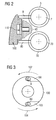
- FIG. 2 shows a radial section in the region of the pins 8 and 80 and shows that the pin 8 is connected to the sleeve 3 and the pin 80 is connected to the sleeve 30.
- FIG. 2 also shows schematically the housing 40 and in this housing an actuating part 100 is rotatably mounted at 110.
- FIG. 3 shows a side view of the parts shown in FIG. 2, and shows that the rotary part 100 has essentially the shape of a flat cylinder and has recesses 101 and 103 on two parts which are essentially opposite to one another by 180 °. In these cuts, the pins 8 and 80 can be seen.
- the incisions 101 and 103 are now designed so that they release the pin 8 in the direction of rotation 102 upon actuation of the actuator 100, while on the pin 80, a movement is transmitted. This is initially a radial movement, but this moves in relation to the associated sleeve 30 in the axial direction.
- the output shaft 407 of the motor can be seen.
- the geometric axis of the output shaft is designated 406.
- a planetary gear 404 is arranged at the free end of the shaft 407. This combs in a pair of sun gears, of which only the result of cutting the rear sun gear 403 can be seen.
- the sun gear 403 rotates as the shaft 406 rotates about an axis 405 that is perpendicular to the plane of the paper.
- the geometric axis 401 of the shaft 7 is aligned with the geometric axis 406 of the motor shaft 407. It can be seen that by spatial separation of the two sun gears 403 from each other, the planet 402 can be taken out of engagement with the sun gears 403 and, for example, in an angle can be engaged again.
- the shaft 7 has been pivoted with respect to the motor shaft 407 by a certain angle. Also in this position, the rotational movements of the motor can be transferred to the tools.
Landscapes
- Engineering & Computer Science (AREA)
- Mechanical Engineering (AREA)
- Gripping On Spindles (AREA)
- Drilling Tools (AREA)
- Drilling And Boring (AREA)
Priority Applications (1)
| Application Number | Priority Date | Filing Date | Title |
|---|---|---|---|
| EP07015692A EP1849563A1 (fr) | 2004-12-09 | 2005-12-09 | Tête d'outil pour un appareil électrique portatif a une perceuse ou visseuse. |
Applications Claiming Priority (1)
| Application Number | Priority Date | Filing Date | Title |
|---|---|---|---|
| DE202004019047U DE202004019047U1 (de) | 2004-12-09 | 2004-12-09 | Werkzeugkopf für ein Elektro-Hand-Arbeitsgerät zum Schrauben und/oder Bohren |
Related Child Applications (1)
| Application Number | Title | Priority Date | Filing Date |
|---|---|---|---|
| EP07015692A Division EP1849563A1 (fr) | 2004-12-09 | 2005-12-09 | Tête d'outil pour un appareil électrique portatif a une perceuse ou visseuse. |
Publications (3)
| Publication Number | Publication Date |
|---|---|
| EP1669166A2 true EP1669166A2 (fr) | 2006-06-14 |
| EP1669166A3 EP1669166A3 (fr) | 2006-07-19 |
| EP1669166B1 EP1669166B1 (fr) | 2008-02-20 |
Family
ID=35953861
Family Applications (2)
| Application Number | Title | Priority Date | Filing Date |
|---|---|---|---|
| EP07015692A Withdrawn EP1849563A1 (fr) | 2004-12-09 | 2005-12-09 | Tête d'outil pour un appareil électrique portatif a une perceuse ou visseuse. |
| EP05026939A Expired - Lifetime EP1669166B1 (fr) | 2004-12-09 | 2005-12-09 | Tête d'outil pour un appareil électrique portatif a une perceuse ou visseuse. |
Family Applications Before (1)
| Application Number | Title | Priority Date | Filing Date |
|---|---|---|---|
| EP07015692A Withdrawn EP1849563A1 (fr) | 2004-12-09 | 2005-12-09 | Tête d'outil pour un appareil électrique portatif a une perceuse ou visseuse. |
Country Status (3)
| Country | Link |
|---|---|
| EP (2) | EP1849563A1 (fr) |
| AT (1) | ATE386615T1 (fr) |
| DE (2) | DE202004019047U1 (fr) |
Families Citing this family (2)
| Publication number | Priority date | Publication date | Assignee | Title |
|---|---|---|---|---|
| EP1985414A1 (fr) | 2007-04-27 | 2008-10-29 | Ferm Corporate B.V. | Tête d'outil pour un outil électrique |
| DE102011087293B4 (de) | 2011-11-29 | 2023-12-21 | Robert Bosch Gmbh | Handwerkzeugmaschine mit einem trommelartigen Werkzeugwechselmagazin |
Citations (1)
| Publication number | Priority date | Publication date | Assignee | Title |
|---|---|---|---|---|
| DE4116343A1 (de) | 1991-05-18 | 1992-11-19 | Bosch Gmbh Robert | Handgefuehrtes elektrowerkzeug, insbesondere bohrmaschine |
Family Cites Families (10)
| Publication number | Priority date | Publication date | Assignee | Title |
|---|---|---|---|---|
| US632560A (en) * | 1898-06-14 | 1899-09-05 | North Brothers Mfg Company | Chuck. |
| US1700975A (en) * | 1926-04-17 | 1929-02-05 | Joseph F Buhr | Drill head |
| DE1628025B2 (de) * | 1967-11-18 | 1976-12-30 | VEB Barkas-Werke, DDR 9010 Karl-Marx-Stadt | Motorgetriebener mehrfachschrauber |
| US3724561A (en) * | 1971-09-09 | 1973-04-03 | F Merrels | Multiple tool driving unit |
| US4296654A (en) * | 1979-08-20 | 1981-10-27 | Mercer Albert E | Adjustable angled socket wrench extension |
| DE3421596A1 (de) * | 1984-06-09 | 1985-12-12 | Helfer & Co KG, 3260 Rinteln | Schraubvorsatz-geraet |
| US4638537A (en) * | 1985-04-22 | 1987-01-27 | Crankshaft Machine Company | Concise quick release tool holder |
| TW301958U (en) * | 1996-06-15 | 1997-04-01 | zheng-nan Qin | Internal formed socket bearing |
| ITBO20020073A1 (it) * | 2002-02-15 | 2003-08-18 | Biesse Spa | Mandrino porta utensili |
| US20040026878A1 (en) * | 2002-03-22 | 2004-02-12 | Tsai-Ching Chen | Chuck device for miniature tool bits |
-
2004
- 2004-12-09 DE DE202004019047U patent/DE202004019047U1/de not_active Expired - Lifetime
-
2005
- 2005-12-09 EP EP07015692A patent/EP1849563A1/fr not_active Withdrawn
- 2005-12-09 DE DE502005002901T patent/DE502005002901D1/de not_active Expired - Lifetime
- 2005-12-09 EP EP05026939A patent/EP1669166B1/fr not_active Expired - Lifetime
- 2005-12-09 AT AT05026939T patent/ATE386615T1/de not_active IP Right Cessation
Patent Citations (1)
| Publication number | Priority date | Publication date | Assignee | Title |
|---|---|---|---|---|
| DE4116343A1 (de) | 1991-05-18 | 1992-11-19 | Bosch Gmbh Robert | Handgefuehrtes elektrowerkzeug, insbesondere bohrmaschine |
Also Published As
| Publication number | Publication date |
|---|---|
| DE502005002901D1 (de) | 2008-04-03 |
| ATE386615T1 (de) | 2008-03-15 |
| DE202004019047U1 (de) | 2006-04-20 |
| EP1669166B1 (fr) | 2008-02-20 |
| EP1669166A3 (fr) | 2006-07-19 |
| EP1849563A1 (fr) | 2007-10-31 |
Similar Documents
| Publication | Publication Date | Title |
|---|---|---|
| DE19925637B4 (de) | Spannfutter | |
| EP2517811B1 (fr) | Dispositif de forage | |
| EP1224048B1 (fr) | Porte-outil | |
| DE60201794T2 (de) | Revolverwerkzeughalter | |
| DE69400262T2 (de) | Motorgetriebenes Gerät und Mechanismus dafür | |
| DE3418881C2 (fr) | ||
| DE1752832C3 (de) | Vorrichtung zur lösbaren Verbindung eines Werkzeugs mit der Spindel einer Werkzeugmaschine | |
| DE4013512A1 (de) | Schalteinrichtung zum umschalten eines kraftgetriebenen werkzeugs | |
| DE9313602U1 (de) | Zweifach-Werkzeugträger für Handbohrmaschinen | |
| EP1952947B1 (fr) | Outil à main motorisé permettant perçage et vissage | |
| DE102007017074A1 (de) | Bohrfutter mit zweistufigem Einspannmechanismus | |
| DE102013113868A1 (de) | Bohrvorrichtung und Bohrfutter | |
| DE3403804A1 (de) | Verfahren zum bearbeiten von werkstuecken mit rotierenden schneidwerkzeugen und spindelmechanismus fuer werkzeugmaschinen zur durchfuehrung dieses verfahrens | |
| DE102014104367A1 (de) | Bohrvorrichtung und Rutschkupplung für eine Bohrvorrichtung | |
| DE1918962A1 (de) | Fraesmaschine zum Bearbeiten gezahnter Werkstuecke,z.B. zum Abfasen der Zahnkanten oder -enden an Zahnraedern | |
| EP0145703B1 (fr) | Chariot transversal pour tour | |
| DE4214838A1 (de) | Spannfutter | |
| WO1999056919A1 (fr) | Machine-outil a changement d'outil | |
| EP1669166B1 (fr) | Tête d'outil pour un appareil électrique portatif a une perceuse ou visseuse. | |
| DE2946307C2 (de) | Tragbares Gerät zum Gewindeschneiden o.dgl. | |
| DE3540223C2 (fr) | ||
| WO2021121783A1 (fr) | Système d'outil | |
| DE102006034963B3 (de) | Rohrschneider | |
| DE2227194C3 (de) | Halter fur Gewindeschneidwerkzeuge | |
| DE10125418A1 (de) | Handwerkzeugmaschine |
Legal Events
| Date | Code | Title | Description |
|---|---|---|---|
| PUAI | Public reference made under article 153(3) epc to a published international application that has entered the european phase |
Free format text: ORIGINAL CODE: 0009012 |
|
| AK | Designated contracting states |
Kind code of ref document: A2 Designated state(s): AT BE BG CH CY CZ DE DK EE ES FI FR GB GR HU IE IS IT LI LT LU LV MC NL PL PT RO SE SI SK TR |
|
| AX | Request for extension of the european patent |
Extension state: AL BA HR MK YU |
|
| PUAL | Search report despatched |
Free format text: ORIGINAL CODE: 0009013 |
|
| AK | Designated contracting states |
Kind code of ref document: A3 Designated state(s): AT BE BG CH CY CZ DE DK EE ES FI FR GB GR HU IE IS IT LI LT LU LV MC NL PL PT RO SE SI SK TR |
|
| AX | Request for extension of the european patent |
Extension state: AL BA HR MK YU |
|
| 17P | Request for examination filed |
Effective date: 20070110 |
|
| AKX | Designation fees paid |
Designated state(s): AT BE BG CH CY CZ DE DK EE ES FI FR GB GR HU IE IS IT LI LT LU LV MC NL PL PT RO SE SI SK TR |
|
| 17Q | First examination report despatched |
Effective date: 20070420 |
|
| GRAP | Despatch of communication of intention to grant a patent |
Free format text: ORIGINAL CODE: EPIDOSNIGR1 |
|
| GRAS | Grant fee paid |
Free format text: ORIGINAL CODE: EPIDOSNIGR3 |
|
| GRAA | (expected) grant |
Free format text: ORIGINAL CODE: 0009210 |
|
| AK | Designated contracting states |
Kind code of ref document: B1 Designated state(s): AT BE BG CH CY CZ DE DK EE ES FI FR GB GR HU IE IS IT LI LT LU LV MC NL PL PT RO SE SI SK TR |
|
| REG | Reference to a national code |
Ref country code: GB Ref legal event code: FG4D Free format text: NOT ENGLISH |
|
| REG | Reference to a national code |
Ref country code: CH Ref legal event code: EP |
|
| REG | Reference to a national code |
Ref country code: IE Ref legal event code: FG4D Free format text: LANGUAGE OF EP DOCUMENT: GERMAN |
|
| REF | Corresponds to: |
Ref document number: 502005002901 Country of ref document: DE Date of ref document: 20080403 Kind code of ref document: P |
|
| PG25 | Lapsed in a contracting state [announced via postgrant information from national office to epo] |
Ref country code: IS Free format text: LAPSE BECAUSE OF FAILURE TO SUBMIT A TRANSLATION OF THE DESCRIPTION OR TO PAY THE FEE WITHIN THE PRESCRIBED TIME-LIMIT Effective date: 20080620 Ref country code: FI Free format text: LAPSE BECAUSE OF FAILURE TO SUBMIT A TRANSLATION OF THE DESCRIPTION OR TO PAY THE FEE WITHIN THE PRESCRIBED TIME-LIMIT Effective date: 20080220 Ref country code: ES Free format text: LAPSE BECAUSE OF FAILURE TO SUBMIT A TRANSLATION OF THE DESCRIPTION OR TO PAY THE FEE WITHIN THE PRESCRIBED TIME-LIMIT Effective date: 20080531 |
|
| NLV1 | Nl: lapsed or annulled due to failure to fulfill the requirements of art. 29p and 29m of the patents act | ||
| PG25 | Lapsed in a contracting state [announced via postgrant information from national office to epo] |
Ref country code: PL Free format text: LAPSE BECAUSE OF FAILURE TO SUBMIT A TRANSLATION OF THE DESCRIPTION OR TO PAY THE FEE WITHIN THE PRESCRIBED TIME-LIMIT Effective date: 20080220 Ref country code: LV Free format text: LAPSE BECAUSE OF FAILURE TO SUBMIT A TRANSLATION OF THE DESCRIPTION OR TO PAY THE FEE WITHIN THE PRESCRIBED TIME-LIMIT Effective date: 20080220 Ref country code: SI Free format text: LAPSE BECAUSE OF FAILURE TO SUBMIT A TRANSLATION OF THE DESCRIPTION OR TO PAY THE FEE WITHIN THE PRESCRIBED TIME-LIMIT Effective date: 20080220 |
|
| REG | Reference to a national code |
Ref country code: IE Ref legal event code: FD4D |
|
| PG25 | Lapsed in a contracting state [announced via postgrant information from national office to epo] |
Ref country code: SE Free format text: LAPSE BECAUSE OF FAILURE TO SUBMIT A TRANSLATION OF THE DESCRIPTION OR TO PAY THE FEE WITHIN THE PRESCRIBED TIME-LIMIT Effective date: 20080520 Ref country code: DK Free format text: LAPSE BECAUSE OF FAILURE TO SUBMIT A TRANSLATION OF THE DESCRIPTION OR TO PAY THE FEE WITHIN THE PRESCRIBED TIME-LIMIT Effective date: 20080220 Ref country code: NL Free format text: LAPSE BECAUSE OF FAILURE TO SUBMIT A TRANSLATION OF THE DESCRIPTION OR TO PAY THE FEE WITHIN THE PRESCRIBED TIME-LIMIT Effective date: 20080220 Ref country code: IE Free format text: LAPSE BECAUSE OF FAILURE TO SUBMIT A TRANSLATION OF THE DESCRIPTION OR TO PAY THE FEE WITHIN THE PRESCRIBED TIME-LIMIT Effective date: 20080220 Ref country code: SK Free format text: LAPSE BECAUSE OF FAILURE TO SUBMIT A TRANSLATION OF THE DESCRIPTION OR TO PAY THE FEE WITHIN THE PRESCRIBED TIME-LIMIT Effective date: 20080220 Ref country code: CZ Free format text: LAPSE BECAUSE OF FAILURE TO SUBMIT A TRANSLATION OF THE DESCRIPTION OR TO PAY THE FEE WITHIN THE PRESCRIBED TIME-LIMIT Effective date: 20080220 |
|
| PG25 | Lapsed in a contracting state [announced via postgrant information from national office to epo] |
Ref country code: RO Free format text: LAPSE BECAUSE OF FAILURE TO SUBMIT A TRANSLATION OF THE DESCRIPTION OR TO PAY THE FEE WITHIN THE PRESCRIBED TIME-LIMIT Effective date: 20080220 |
|
| EN | Fr: translation not filed | ||
| PLBE | No opposition filed within time limit |
Free format text: ORIGINAL CODE: 0009261 |
|
| STAA | Information on the status of an ep patent application or granted ep patent |
Free format text: STATUS: NO OPPOSITION FILED WITHIN TIME LIMIT |
|
| 26N | No opposition filed |
Effective date: 20081121 |
|
| PG25 | Lapsed in a contracting state [announced via postgrant information from national office to epo] |
Ref country code: LT Free format text: LAPSE BECAUSE OF FAILURE TO SUBMIT A TRANSLATION OF THE DESCRIPTION OR TO PAY THE FEE WITHIN THE PRESCRIBED TIME-LIMIT Effective date: 20080220 |
|
| PG25 | Lapsed in a contracting state [announced via postgrant information from national office to epo] |
Ref country code: FR Free format text: LAPSE BECAUSE OF FAILURE TO SUBMIT A TRANSLATION OF THE DESCRIPTION OR TO PAY THE FEE WITHIN THE PRESCRIBED TIME-LIMIT Effective date: 20081212 Ref country code: EE Free format text: LAPSE BECAUSE OF FAILURE TO SUBMIT A TRANSLATION OF THE DESCRIPTION OR TO PAY THE FEE WITHIN THE PRESCRIBED TIME-LIMIT Effective date: 20080220 Ref country code: BG Free format text: LAPSE BECAUSE OF FAILURE TO SUBMIT A TRANSLATION OF THE DESCRIPTION OR TO PAY THE FEE WITHIN THE PRESCRIBED TIME-LIMIT Effective date: 20080520 |
|
| BERE | Be: lapsed |
Owner name: KLEIN & MORE Effective date: 20081231 |
|
| PG25 | Lapsed in a contracting state [announced via postgrant information from national office to epo] |
Ref country code: CY Free format text: LAPSE BECAUSE OF FAILURE TO SUBMIT A TRANSLATION OF THE DESCRIPTION OR TO PAY THE FEE WITHIN THE PRESCRIBED TIME-LIMIT Effective date: 20080220 Ref country code: MC Free format text: LAPSE BECAUSE OF NON-PAYMENT OF DUE FEES Effective date: 20081231 |
|
| PG25 | Lapsed in a contracting state [announced via postgrant information from national office to epo] |
Ref country code: IT Free format text: LAPSE BECAUSE OF FAILURE TO SUBMIT A TRANSLATION OF THE DESCRIPTION OR TO PAY THE FEE WITHIN THE PRESCRIBED TIME-LIMIT Effective date: 20080220 |
|
| PG25 | Lapsed in a contracting state [announced via postgrant information from national office to epo] |
Ref country code: BE Free format text: LAPSE BECAUSE OF NON-PAYMENT OF DUE FEES Effective date: 20081231 |
|
| PG25 | Lapsed in a contracting state [announced via postgrant information from national office to epo] |
Ref country code: AT Free format text: LAPSE BECAUSE OF NON-PAYMENT OF DUE FEES Effective date: 20081209 |
|
| PG25 | Lapsed in a contracting state [announced via postgrant information from national office to epo] |
Ref country code: LU Free format text: LAPSE BECAUSE OF NON-PAYMENT OF DUE FEES Effective date: 20081209 Ref country code: HU Free format text: LAPSE BECAUSE OF FAILURE TO SUBMIT A TRANSLATION OF THE DESCRIPTION OR TO PAY THE FEE WITHIN THE PRESCRIBED TIME-LIMIT Effective date: 20080821 |
|
| REG | Reference to a national code |
Ref country code: CH Ref legal event code: PL |
|
| GBPC | Gb: european patent ceased through non-payment of renewal fee |
Effective date: 20091209 |
|
| PG25 | Lapsed in a contracting state [announced via postgrant information from national office to epo] |
Ref country code: TR Free format text: LAPSE BECAUSE OF FAILURE TO SUBMIT A TRANSLATION OF THE DESCRIPTION OR TO PAY THE FEE WITHIN THE PRESCRIBED TIME-LIMIT Effective date: 20080220 |
|
| PG25 | Lapsed in a contracting state [announced via postgrant information from national office to epo] |
Ref country code: GR Free format text: LAPSE BECAUSE OF FAILURE TO SUBMIT A TRANSLATION OF THE DESCRIPTION OR TO PAY THE FEE WITHIN THE PRESCRIBED TIME-LIMIT Effective date: 20080521 Ref country code: LI Free format text: LAPSE BECAUSE OF NON-PAYMENT OF DUE FEES Effective date: 20091231 Ref country code: CH Free format text: LAPSE BECAUSE OF NON-PAYMENT OF DUE FEES Effective date: 20091231 |
|
| PG25 | Lapsed in a contracting state [announced via postgrant information from national office to epo] |
Ref country code: GB Free format text: LAPSE BECAUSE OF NON-PAYMENT OF DUE FEES Effective date: 20091209 |
|
| PG25 | Lapsed in a contracting state [announced via postgrant information from national office to epo] |
Ref country code: PT Free format text: LAPSE BECAUSE OF FAILURE TO SUBMIT A TRANSLATION OF THE DESCRIPTION OR TO PAY THE FEE WITHIN THE PRESCRIBED TIME-LIMIT Effective date: 20080220 |
|
| PGFP | Annual fee paid to national office [announced via postgrant information from national office to epo] |
Ref country code: DE Payment date: 20120107 Year of fee payment: 7 |
|
| REG | Reference to a national code |
Ref country code: DE Ref legal event code: R119 Ref document number: 502005002901 Country of ref document: DE Effective date: 20130702 |
|
| PG25 | Lapsed in a contracting state [announced via postgrant information from national office to epo] |
Ref country code: DE Free format text: LAPSE BECAUSE OF NON-PAYMENT OF DUE FEES Effective date: 20130702 |