EP1665236B1 - Optische aufzeichnungs-/wiedergabevorrichtung und verfahren zur bestimmung ihrer optischen leistung - Google Patents
Optische aufzeichnungs-/wiedergabevorrichtung und verfahren zur bestimmung ihrer optischen leistung Download PDFInfo
- Publication number
- EP1665236B1 EP1665236B1 EP04701129A EP04701129A EP1665236B1 EP 1665236 B1 EP1665236 B1 EP 1665236B1 EP 04701129 A EP04701129 A EP 04701129A EP 04701129 A EP04701129 A EP 04701129A EP 1665236 B1 EP1665236 B1 EP 1665236B1
- Authority
- EP
- European Patent Office
- Prior art keywords
- recording
- values
- optical disk
- combination
- combinations
- Prior art date
- Legal status (The legal status is an assumption and is not a legal conclusion. Google has not performed a legal analysis and makes no representation as to the accuracy of the status listed.)
- Expired - Lifetime
Links
Images
Classifications
-
- G—PHYSICS
- G11—INFORMATION STORAGE
- G11B—INFORMATION STORAGE BASED ON RELATIVE MOVEMENT BETWEEN RECORD CARRIER AND TRANSDUCER
- G11B7/00—Recording or reproducing by optical means, e.g. recording using a thermal beam of optical radiation by modifying optical properties or the physical structure, reproducing using an optical beam at lower power by sensing optical properties; Record carriers therefor
- G11B7/004—Recording, reproducing or erasing methods; Read, write or erase circuits therefor
- G11B7/0045—Recording
-
- G—PHYSICS
- G11—INFORMATION STORAGE
- G11B—INFORMATION STORAGE BASED ON RELATIVE MOVEMENT BETWEEN RECORD CARRIER AND TRANSDUCER
- G11B7/00—Recording or reproducing by optical means, e.g. recording using a thermal beam of optical radiation by modifying optical properties or the physical structure, reproducing using an optical beam at lower power by sensing optical properties; Record carriers therefor
- G11B7/12—Heads, e.g. forming of the optical beam spot or modulation of the optical beam
- G11B7/125—Optical beam sources therefor, e.g. laser control circuitry specially adapted for optical storage devices; Modulators, e.g. means for controlling the size or intensity of optical spots or optical traces
- G11B7/126—Circuits, methods or arrangements for laser control or stabilisation
- G11B7/1267—Power calibration
Definitions
- the present invention relates to an optical disk recording/reproducing apparatus and a method for determining optimal power thereof, and more particularly, to an optical disc recording/reproducing apparatus and a method for determining power optimal for the characteristics of an optical disk in order for data to be recorded in an optimal state when the data is recorded on the optical disk.
- optical disks are classified into reproduction-dedicated disks such as compact disk-ROM (CD-ROM), Digital Versatile disk-ROM (DVD-ROM), and the like, write-once recordable disks such as CD-Recordable (CD-R), DVD-R, and the like, and rewritable disks such as CD-Rewritable (CD-RW), DVD-RAM, and the like, depending upon data record capability.
- reproduction-dedicated disks such as compact disk-ROM (CD-ROM), Digital Versatile disk-ROM (DVD-ROM), and the like
- write-once recordable disks such as CD-Recordable (CD-R), DVD-R, and the like
- rewritable disks such as CD-Rewritable (CD-RW), DVD-RAM, and the like, depending upon data record capability.
- An optical disk recording/reproducing apparatus can drive a laser diode (LD) provided on an optical pickup to record information onto an optical disk or reproduce recorded information from the optical disk.
- the optical disk recording/reproducing apparatus drives the laser diode (LD) to irradiate a laser beam of relatively high power since the physical characteristics of an information recording layer existing on the optical disk have to be changed, and, in order to reproduce information recorded on the optical disk, the optical disk recording/reproducing apparatus drives the laser diode (LD) to irradiate a laser beam of relatively low power since the physical characteristics of the information recording layer do not have to be changed.
- the optimal recording power changes depending upon the characteristics of each optical disk such as optical disk kind, optical disk maker, chemical properties of recording layers of optical disks, and so on. Accordingly, most optical disk recording/reproducing apparatuses are designed to perform a process for determining an optimal recording power at the initial stage.
- the optimal power is determined by performing recording tests on a certain area of an optical disk.
- the number of parameters to be determined to obtain the optimal power is increasing together with the recent commercialization of optical disk recording/reproducing apparatuses that can record and reproduce information onto and from diverse kinds of optical disks. Accordingly, it takes lots of time to perform recording tests for all possible combinations of the parameter values, so a method is required to solve such a problem.
- US 2003/0035355 discloses an optimal power determination method for recording/reproducing information onto and out of an optical disk, comprising the steps of:
- the present invention provides an optimal power determination method for recording information onto an optical disk, comprising the steps of:
- the time required for optimal power determination is reduced as combinations which are not included in the combination table are predicted based on jitter value obtained through the recording tests.
- the combination table includes a limited number of combinations.
- the present invention performs recording tests as to each combination, and computes an optimal value for each parameter in consideration of interrelations with the other parameters from test results. That is, the combinations of values in the combination table are pre-selected values for the recording tests, and any one of the combinations is not determined as an optimal combination, but optimal parameter values are inferred and determined from the results of the recording tests. By doing so, the present invention can find out optimal parameter values in a short time period in consideration of mutual influences among parameters with the recording tests performed as many as the predetermined number of times.
- each combination table is an orthogonal array table formed with a few values pre-selected with respect to all the parameters required for optimal power determination.
- the orthogonal array table has been one of experiment methods for finding out an optimal condition with minimum cases in consideration of influences among elements.
- At least one combination table is prepared and stored by optical disk kind. Therefore, an optical disk recording/reproducing apparatus determines the kind of a disk when the disk is loaded therein, reads out a corresponding combination table of the pre-stored combination tables depending upon the disk kinds, and performs recording tests to determine an optical power.
- the parameters to be determined can be easily understood by those skilled in the art to which the present invention pertains, and values of the parameters for performing the recording tests can be easily set through experiences and experiments by those skilled in the art, on which detailed descriptions will be omitted.
- the present invention relates to a method for determining optimal power for recording/reproducing optical disks, so the present invention can be applied to all apparatuses for recording/reproducing optical disks such as CD, DVD, BD, and the like.
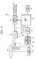
- Fig. 1 is a schematic block diagram for showing an optical disk recording/reproducing apparatus according to a preferred embodiment of the present invention.
- the optical disk recording/reproducing apparatus 100 has a pickup unit 110, an RF unit 120, a recording/reproducing unit 130, a servo unit 140, a driving unit 150, a spindle motor 160, a memory unit 170, and a control unit 180.
- Fig. 1 is a view for showing only units (shown in blocks) related to the optimal power determination from the optical disk recording/reproducing apparatus 100 according to the present invention, and the other blocks are not shown for the sake of explanations.
- the pickup unit 110 irradiates a laser beam onto an optical disk 100a to record data, and reads out and reproduces the data recorded on the optical disk 100a.
- the pickup unit 110 includes a laser diode (LD) for irradiating a laser beam of certain power onto the optical disk 100a, an object lens for focusing the beam irradiated from the LD onto the surface of the optical disk 100a, a photo diode (PD) which is a sensor for detecting a beam reflected from the surface of the optical disk 100a, a focusing actuator for driving the object lens upwards and downwards to precisely focus the beam irradiated from the LD onto the surface of the optical disk 100a, a tracking actuator for driving the object lens to the left and right in order for the pickup unit 110 to precisely trace the tracks formed on the optical disk 100a, and so on.
- LD laser diode
- PD photo diode
- a focusing actuator for driving the object lens upwards and downwards to precisely focus the beam irradi
- the RF unit 120 amplifies and rectifies an RF signal outputted from the pickup unit 110 into a modulated signal such as an Eight to Fourteen modulation (EFM) signal, and provides the EFM signal to the recording/reproducing unit 130. Further, the RF unit 120 detects a focusing error (FE) and a tracking error (TE) from the RF signal, and applies an FE signal and a TE signal corresponding to the detected errors to the control unit 180 and the servo unit 140.
- EFM Eight to Fourteen modulation
- the recording/reproducing unit 130 records on the optical disk 100a a recording signal externally inputted according to a recording command signal sent from the control unit 180 which will be later described, and reads out and reproduces data recorded on the optical disk 100a according to a reproducing command signal. That is, if the recording command signal is inputted from the control unit 180, the recording/reproducing unit 130 converts a recording signal or a test recording signal for setting a recording power, which is inputted in accordance with the recording command signal, into a format of data for an output that can be recorded on the optical disk 100a. Further, if the reproducing command signal is received from the control unit 180, the recording/reproducing unit 130 reads out the data recorded on the optical disk 100a, and decodes and reproduces the read-out data.
- the servo unit 140 controls a focusing servo and a tracking servo based on the TE signal and FE signal that are outputted from the RF unit 120. Further, the servo unit 140 controls a motor driving unit 154 for controlling the spindle motor 160, which is a driving motor for the optical disk 100a, to be driven at a constant linear velocity(hereinafter, referred to as "CLV"), and an LD driving unit 152 for driving the laser diode to emit a laser beam corresponding to a recording power and a reproducing power.
- CLV constant linear velocity
- the driving unit 150 has the LD driving unit 152 and the motor driving unit 154.
- the LD driving unit 152 drives the laser diode based on the controls of the servo unit 140. For example, the LD driving unit 152 drives the laser diode to output a laser beam corresponding to a recording power and a reproducing power necessary for recording certain data on the optical disk 100a and reproducing the recorded data on the optical disk 100a.
- the motor driving unit 154 supplies to the spindle motor 160 a driving voltage for driving the spindle motor 160 according to a rotation speed control signal for the spindle motor 160 that is outputted from the servo unit 140. That is, the motor driving unit 154 drives the spindle motor 160 to rotate the optical disk 100a at a constant linear velocity.
- the spindle motor 160 is a DC motor for rotating the optical disk 100a, and rotates forwards and reversely depending upon a driving voltage supplied from the motor driving unit 154.
- the memory unit 170 consists of a ROM for storing control programs for controlling various operations of the optical disk recording/reproducing apparatus 100 and a RAM for temporarily storing various data occurring during the various operations. Further, the memory unit 170 according to the present embodiment stores combination tables each formed with combinations of pre-selected values with respect to respective parameters for determining an optimal power for a laser beam emitted from the pickup unit 110. It is preferable that at least one combination table is prepared and stored by optical disk kind. Each combination table is formed in an orthogonal array of values pre-selected for parameters required for optimal power determination.
- the parameters for determining an optimal power may include power-related parameters such as Write Power, Erase Power, Bias Power, Peak Power, and the like, time-related parameters such as Delay Pulse, Write Pulse, Last Pulse, Off Pulse, and so on, but not limited to the above parameters.
- power-related parameters such as Write Power, Erase Power, Bias Power, Peak Power, and the like
- time-related parameters such as Delay Pulse, Write Pulse, Last Pulse, Off Pulse, and so on, but not limited to the above parameters.
- the control unit 180 controls overall operations of the optical disk recording/reproducing apparatus 100 according to the various control programs stored in the memory unit 170.
- the control unit 180 operates the optical disk recording/reproducing apparatus 100 in a record mode for recording to-be-recorded data (hereinafter, referred to as record data) on a loaded optical disk 100a or in a reproducing mode for reproducing data recorded on the optical disk 100a according to an operation mode.
- the control unit 180 determines the kind of an optical disk 100a based on a signal outputted from the RF unit 120 in correspondence with the loaded optical disk 100a. For example, the control unit 180 determines the kind of an optical disk 100a based on the level of an FE signal outputted from the RF unit 120, but not limited to this fashion.
- the optical disk is classified into any one of CD-ROM, CD-R, CD-RW, DVD-ROM, DVD-R, DVD-RW, and DVD-RAM depending upon the level of the FE signal.
- the control unit 180 performs an optimal record power control (OPC) process for determining power optimal for the loaded optical disk 100a.
- OPC optimal record power control
- the OPC process can be implemented to be immediately carried out if the optical disk 100a is determined as a recordable disk, and, in another way, the OPC process can be implemented to be carried out before a recording job is performed with a recording request signal externally received.
- the recording request signal can be received through a key operation unit(not shown) provided on the main body of the optical disk recording/reproducing apparatus 100 or a remote controller(not shown).
- the control unit 180 reads out of the memory unit 170 a combination table corresponding to the kind of the loaded optical disk 100a, performs recording tests with combinations listed on the read-out combination table, and determines an optimal power based on a result of the performance.
- the control unit 180 temporarily stores in the memory unit 170 a first jitter value which is a first recording state information value obtained from the recording tests done with the combinations listed on the combination table. Further, the control unit 180 predicts a result value as to a combination of parameter values not included on the combination table based on the jitter value stored in the memory unit 170, and calculates a second jitter value which is a second recording state information value. The control unit 180 decides as an optimal combination a combination having the minimum jitter value out of the first recording state information value and the second recording state information value. Detailed descriptions on a method for deciding the optimal combination will later made in detail.
- the control unit 180 stores in the memory unit 170 values of the parameters corresponding to the decided optimal combination. Thereafter, if the recording request signal is received through the key operation unit, the control unit 180 processes a recording job with optimal parameter values stored in the memory unit 170.
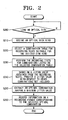
- the control unit 180 recognizes the kind of the loaded optical disk 100a (S210). If the loaded optical disk 100a is recognized to be a recordable disk, the control unit 180 reads out of the memory unit 170 a combination table corresponding to the loaded optical disk 100a (S220).
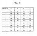
- Fig. 3 is a view for illustrating a combination table for recording tests.
- Fig. 3 illustrates a combination table corresponding to a disk requiring four parameters such as Peak Power P P , Bias Power P B , Cooling Pulse T C , and Last Pulse T L in order to determine an optimal power.
- Each parameter has three different pre-selected parameter values. That is, there are 15mW, 16mW, and 17mW selected for the P P value, 6mW, 7mW, and 8mW selected for the P B value. Further, there are 5ns, 6ns, and 7ns selected for the T C value, and 4ns, 5ns, and 6ns selected for the T L value.
- the present invention is not limited to parameters and values, but can have more parameters such as Write Power, Erase Power, Write Pulse, Off Pulse, and the like, in addition to the above parameters according to the characteristics of a loaded optical disk.
- the control unit 180 records test data onto the optical disk 100a in use of parameter values set in each of the certain combinations (nine combinations as shown in Fig. 3 ) listed on the read-out combination table, and reproduces the recorded test data to perform the recording tests calculating jitter values (S230). At this time, the test data is recorded in a Power Calibration Area (PCA) which is a test area for determining an optimal power.
- PCA Power Calibration Area
- control unit 180 predicts a result value with respect to the other combinations for which the recording tests are not carried out, based on the jitter value obtained from a recording test performance, and calculates a second recording state information value (S240).
- a second recording state information value S240.
- 81 combinations can be made in use of four parameters required for optima power determination and three values predetermined for each of the parameters.
- the present embodiment can determine parameter values for an optimal power without carrying out the recording tests as to the 81 combinations. That is, the present invention performs the recording tests as to only 9 combinations listed on a combination table, and predicts parameter values as to the other combinations not included on the combination table based on jitter values obtained from the recording test performances.
- the MSD 1 denotes a jitter value obtained through a recording test as to the combination 1
- SNR 1 denotes a signal-to-noise ratio for the MSD 1
- yl to yn denote the number of times the record tests are carried out as to the combination 1.
- the SNRs can be calculated with respect to the remaining combinations, that is, combination 2 to combination 9, in use of Equation 1.
- the SNR is calculated with respect to each combination according to the above method, it can be seen how parameter values corresponding to the elements P P , P B , T C , and T L affect SNRs in use of the calculated SNR. For example, if an average value over SNR 1 , SNR 2 , and SNR 3 calculated for combinations 1, 2, and 3 is calculated, it can be seen what an SNR would be in case that the first parameter value (15mW) of P B is selected, and, if an average value over SNR 1 , SNR 4 , and SNR 7 calculated for combinations 1, 4, and 7 is calculated, it can be seen what an SNR would be in case that the first parameter (6mW) of P B is selected.
- the SNR can be calculated when the respective parameters are selected with respect to the remaining elements. In this case, a combination of parameter values having the largest SNR with respect to the respective elements can be predicted as an optimal combination.
- the control unit 180 extracts an optimal combination having a minimum jitter value from a jitter value obtained from recording test performances and a jitter value predicted based on the jitter value (S250). For example, the control unit 180 extracts the predetermined number of combinations out of the 81 combinations, for example, three combinations, in ascending order of combination jitter values, that is, the least jitter value, the second least jitter value, and the third least jitter value, and the recording tests are performed with respect to the predetermined number of extracted combinations.
- the control unit 180 calculates a jitter value for the predetermined number of combinations as to which the recording tests are performed, and determines as an optimal combination the combination having the minimum jitter value of the calculated jitter values. At this time, the recording tests are not necessary for the combinations out of the predetermined number of extracted combinations as to which the recording tests have been carried out.
- control unit 180 predicts jitter values for the other combinations, that is, 72 combinations, based on the jitter value obtained through the recording tests, and extracts the predetermined number of combinations out of the other combinations, for example, three combinations, in ascending order of combination jitter values. Further, the control unit 180 carries out the recording tests for the predetermined number of extracted combinations. The control unit 180 compares the jitter values obtained through the recording test performance with respect to the three combinations to the jitter values obtained through the recording test performance with respect to the combinations listed on the combination table, and determines as an optimal combination the combination having a minimum jitter value as a result of the comparison.
- the parameter values that the optimal combination determined in the above method has become the optimal parameter values for determining an optimal power.
- the control unit 180 stores the determined optimal parameter values in the memory unit 170. Thereafter, if a recording request signal is received for record data through a key operation unit, the control unit 180 processes a recording job with optimal parameter values stored in the memory unit 170 (S260).
- the present invention can carry out recording tests in use of combination tables each formed with combinations of parameter values required for optimal power determination, predict a result for combinations not included on the combination tables based on jitter values obtained through the recording tests, and determine optimal parameter values having an optimal power. That is, the present invention can determine optimal parameter values for an optimal power with the recording tests carried out only the predetermined number of times, to thereby reduce time required for the optimal power determination.
Landscapes
- Physics & Mathematics (AREA)
- Optics & Photonics (AREA)
- Optical Recording Or Reproduction (AREA)
- Optical Head (AREA)
Claims (7)
- Verfahren zur Bestimmung optimaler Leistung zwecks Aufzeichnens von Informationen auf einer optischen Platte, umfassend die Schritte:Feststellen (S210) einer Art einer geladenen optischen Platte und Auslesen (S220) einer Kombinationstabelle, die der festgestellten Art der geladenen optischen Platte entspricht, vor Durchführen der Aufzeichnungstests, wobei die Kombinationstabellen nach Art optischer Platte im Voraus erstellt und gespeichert werden, und wobei jede der Kombinationstabellen eine Mehrzahl von Kombinationen vorgewählter Werte für Parameter zur Bestimmung optimaler Leistung umfasst;Durchführen (S230) von Aufzeichnungstests für jede aus der Mehrzahl von Kombinationen vorgewählter Werte für Parameter zur Bestimmung optimaler Leistung,Bestimmen (S240, S250) optimaler Werte für die Parameter anhand eines Ergebnisses einer Aufzeichnungstestdurchführung, um die Leistung zu bestimmen, wobei der Schritt zur Bestimmung der optimalen Werte eine Kombination der Parameterwerte bestimmt auf Grundlage erster Aufzeichnungszustandsinformationswerte, erhalten als Ergebnis der Aufzeichnungstests, und zweiter Aufzeichnungszustandsinformationswerte, berechnet aus Vorhersagen von Ergebnissen für nicht in den Kombinationstabellen enthaltene Kombinationen von Parameterwerten anhand der ersten Aufzeichnungszustandsinformationswerte.
- Verfahren zur Bestimmung optimaler Leistung nach Anspruch 1, wobei jede Kombinationstabelle in einem orthogonalen Feld der Werte der Parameter zur Bestimmung optimaler Leistung gebildet wird.
- Verfahren zur Bestimmung optischer Leistung nach Anspruch 1 oder 2, wobei die Aufzeichnungstests vorgenommen werden durch Aufzeichnen von Testdaten auf der optischen Platte und Messen eines aus einem Wiedergabesignal für die aufgezeichneten Testdaten errechneten Jitterwerts.
- Verfahren zur Bestimmung optischer Leistung nach Anspruch 3, wobei im Schritt zur Bestimmung der optimalen Werte die vorgegebene Anzahl an Kombinationen, die laut Vorhersage den niedrigsten Jitterwert unter den zweiten Aufzeichnungszustandsinformationswerten aufweisen, extrahiert wird, dritte Aufzeichnungszustandsinformationswerte erhalten werden durch Vornehmen der Aufzeichnungstests für die extrahierten Kombinationen, und als optimale Kombination eine Kombination bestimmt wird, die den niedrigsten Jitterwert unter den ersten Aufzeichnungszustandsinformationswerten und den dritten Aufzeichnungszustandsinformationswerten aufweist.
- Aufzeichnungsgerät (100) für optische Platten zum Aufzeichnen von Informationen auf einer optischen Platte, umfassend:eine Abtast- bzw. Pickup-Einheit (110) zum Werfen eines Strahls auf die optische Platte und zum Aufzeichnen von Informationen;eine Speichereinheit (170) zur Speicherung von Kombinationstabellen, die jeweils im Voraus gebildet und erfasst werden mit einer Mehrzahl von Kombinationen vorgewählter Werte für Parameter zur Bestimmung einer optimalen Leistung des aus der Abtast- bzw. Pickup-Einheit geworfenen Strahls,eine Steuerungseinheit (180) zur Durchführung von Aufzeichnungstests unter Verwendung der Kombinationstabellen, wobei die Steuerungseinheit angepasst ist, um eine Kombination der Parameterwerte zu bestimmen auf Grundlage erster Aufzeichnungszustandsinformationswerte, erhalten als Ergebnis der Aufzeichnungstests, und zweiter Aufzeichnungszustandsinformationswerte, berechnet aus Vorhersagen von Ergebnissen für nicht in den Kombinationstabellen enthaltene Kombinationen von Parameterwerten anhand der ersten Aufzeichnungszustandsinformationswerte; undwobei die Kombinationstabellen erstellt und gespeichert werden in der Speichereinheit nach Art optischer Platte, und die Steuerungseinheit angepasst ist, um eine Art einer geladenen optischen Platte festzustellen und um eine Kombinationstabelle, die der festgestellten Art der geladenen optischen Platte entspricht, auszulesen vor Durchführung der Aufzeichnungstests.
- Aufzeichnungsgerät für optische Platten nach Anspruch 5, wobei die Kombinationstabellen jeweils in einem orthogonalen Feld von Werten für Parameter zur Bestimmung der optischen Leistung gebildet werden.
- Aufzeichnungsgerät für optische Platten nach Anspruch 5 oder 6, wobei die optimale Leistung bestimmt wird durch Extrahieren der vorgegebenen Anzahl an Kombinationen, die laut Vorhersage den niedrigsten Jitterwert unter den zweiten Aufzeichnungszustandsinformationswerten aufweisen, durch Erhalten dritter Aufzeichnungszustandsinformationswerte mittels Aufzeichnungstestdurchführungen für die extrahierten Kombinationen, und durch Auswählen einer Kombination, die den niedrigsten Jitterwert unter den ersten Aufzeichnungszustandsinformationswerten und den dritten Aufzeichnungszustandsinformationswerten aufweist.
Applications Claiming Priority (2)
| Application Number | Priority Date | Filing Date | Title |
|---|---|---|---|
| KR1020030063383A KR100950490B1 (ko) | 2003-09-09 | 2003-09-09 | 광 기록/재생장치 및 그의 최적 파워 결정방법 |
| PCT/KR2004/000026 WO2005024802A1 (en) | 2003-09-09 | 2004-01-09 | Optical recording /reproducing apparatus and method for determining optical power thereof |
Publications (3)
| Publication Number | Publication Date |
|---|---|
| EP1665236A1 EP1665236A1 (de) | 2006-06-07 |
| EP1665236A4 EP1665236A4 (de) | 2008-03-19 |
| EP1665236B1 true EP1665236B1 (de) | 2010-05-12 |
Family
ID=36242081
Family Applications (1)
| Application Number | Title | Priority Date | Filing Date |
|---|---|---|---|
| EP04701129A Expired - Lifetime EP1665236B1 (de) | 2003-09-09 | 2004-01-09 | Optische aufzeichnungs-/wiedergabevorrichtung und verfahren zur bestimmung ihrer optischen leistung |
Country Status (7)
| Country | Link |
|---|---|
| US (1) | US7313064B2 (de) |
| EP (1) | EP1665236B1 (de) |
| JP (1) | JP4091961B2 (de) |
| KR (1) | KR100950490B1 (de) |
| CN (1) | CN100375998C (de) |
| DE (1) | DE602004027151D1 (de) |
| WO (1) | WO2005024802A1 (de) |
Families Citing this family (9)
| Publication number | Priority date | Publication date | Assignee | Title |
|---|---|---|---|---|
| WO2006043201A1 (en) * | 2004-10-18 | 2006-04-27 | Koninklijke Philips Electronics N.V. | Device and method for providing media-related parameters on a medium and for retrieving such parameters |
| US7675826B2 (en) | 2005-09-23 | 2010-03-09 | Marvell World Trade Ltd. | Automatic write strategy calibration method for optical drive |
| JP2007149182A (ja) * | 2005-11-25 | 2007-06-14 | Hitachi Ltd | 光ディスク記録装置の記録制御方法及び光ディスク記録装置 |
| JP2007299471A (ja) * | 2006-04-28 | 2007-11-15 | Fujitsu Ltd | 再生装置製造方法、記録媒体および検査プログラム |
| JP4561699B2 (ja) * | 2006-06-26 | 2010-10-13 | 日本ビクター株式会社 | 記録再生装置 |
| US8174944B1 (en) * | 2007-01-30 | 2012-05-08 | Marvell International Ltd. | Write strategy calibration for optical drives |
| CN102388419A (zh) * | 2009-04-10 | 2012-03-21 | 三菱电机株式会社 | 光盘再现功率设定方法、光盘再现方法及光盘装置 |
| JP5322771B2 (ja) * | 2009-05-18 | 2013-10-23 | 三菱電機株式会社 | 光記録装置及び方法 |
| KR101557116B1 (ko) | 2013-11-13 | 2015-10-02 | 주식회사 케이티 | 개별 부하의 운영상태를 추정하는 장치 및 방법 |
Family Cites Families (25)
| Publication number | Priority date | Publication date | Assignee | Title |
|---|---|---|---|---|
| JPH0916964A (ja) * | 1995-06-26 | 1997-01-17 | Pioneer Electron Corp | 光学式記録媒体および光ビームの供給パワー設定方法 |
| EP0905685A1 (de) * | 1996-09-05 | 1999-03-31 | Nikon Corporation | Optisches aufzeichnungsverfahren und optisches aufzeichnungsgerat |
| JP3429166B2 (ja) * | 1997-08-28 | 2003-07-22 | 富士通株式会社 | 光学的記憶装置 |
| JPH11149641A (ja) * | 1997-09-05 | 1999-06-02 | Nikon Corp | 光記録方法および光記録装置 |
| JPH11232681A (ja) * | 1998-02-13 | 1999-08-27 | Fujitsu Ltd | 光学的情報記憶装置 |
| US6292448B1 (en) * | 1998-07-27 | 2001-09-18 | Pioneer Corporation | Information recording apparatus |
| JP3076033B1 (ja) * | 1998-09-14 | 2000-08-14 | 松下電器産業株式会社 | 光学情報の記録再生装置および情報記録媒体 |
| JP3718082B2 (ja) * | 1998-10-26 | 2005-11-16 | 株式会社リコー | 光ディスク記録装置 |
| WO2000028535A1 (en) * | 1998-11-06 | 2000-05-18 | Matsushita Electric Industrial Co., Ltd. | Method and device for finding conditions on recording pulse of optical disk |
| KR100618548B1 (ko) * | 2000-01-06 | 2006-08-31 | 주식회사 엘지이아이 | 광기록재생장치의 기록 파워 제어 방법 |
| JP3784610B2 (ja) | 2000-04-14 | 2006-06-14 | 株式会社リコー | 情報記録再生装置 |
| JP3496628B2 (ja) * | 2000-05-31 | 2004-02-16 | ヤマハ株式会社 | 光ディスク記録方法および光ディスク記録装置 |
| JP3450821B2 (ja) * | 2000-11-16 | 2003-09-29 | パイオニア株式会社 | 光学式記録媒体、光ビームのパワー設定方法および記録装置 |
| JP2002230779A (ja) * | 2001-01-30 | 2002-08-16 | Sanyo Electric Co Ltd | ディスク再生装置 |
| JP3858613B2 (ja) * | 2001-03-23 | 2006-12-20 | ティアック株式会社 | 光ディスク装置 |
| JP4474813B2 (ja) * | 2001-08-20 | 2010-06-09 | ヤマハ株式会社 | 光ディスク記録方法 |
| JP3801000B2 (ja) * | 2001-08-27 | 2006-07-26 | ティアック株式会社 | 光ディスク装置 |
| JP3820965B2 (ja) * | 2001-09-04 | 2006-09-13 | 日本電気株式会社 | 情報記録媒体の記録再生条件調整方法及びそれを用いた記録再生装置 |
| JP2003085761A (ja) * | 2001-09-14 | 2003-03-20 | Ricoh Co Ltd | 光ディスク装置 |
| JP2003091852A (ja) * | 2001-09-17 | 2003-03-28 | Ricoh Co Ltd | 光ディスク記録再生装置及びレーザパワー決定方法 |
| JP2003203341A (ja) * | 2001-11-02 | 2003-07-18 | Victor Co Of Japan Ltd | 光ディスク、光ディスク記録再生装置及び光ディスク記録再生方法 |
| JP2003317251A (ja) * | 2002-02-21 | 2003-11-07 | Ricoh Co Ltd | 光ディスク装置、光記録方法、光記録プログラムおよび記憶媒体 |
| JP3979120B2 (ja) * | 2002-02-25 | 2007-09-19 | ティアック株式会社 | 光ディスク装置 |
| JP2004046966A (ja) * | 2002-07-11 | 2004-02-12 | Ricoh Co Ltd | 光情報記録媒体、記録条件決定方法、光情報記録装置及び情報処理装置 |
| TW577060B (en) * | 2002-07-25 | 2004-02-21 | Mediatek Inc | Calibrating method of writing power for optical storage medium |
-
2003
- 2003-09-09 KR KR1020030063383A patent/KR100950490B1/ko not_active Expired - Fee Related
-
2004
- 2004-01-09 JP JP2006523775A patent/JP4091961B2/ja not_active Expired - Fee Related
- 2004-01-09 EP EP04701129A patent/EP1665236B1/de not_active Expired - Lifetime
- 2004-01-09 WO PCT/KR2004/000026 patent/WO2005024802A1/en not_active Ceased
- 2004-01-09 DE DE602004027151T patent/DE602004027151D1/de not_active Expired - Lifetime
- 2004-01-09 CN CNB2004800142755A patent/CN100375998C/zh not_active Expired - Fee Related
- 2004-09-01 US US10/931,036 patent/US7313064B2/en not_active Expired - Fee Related
Also Published As
| Publication number | Publication date |
|---|---|
| KR20050026654A (ko) | 2005-03-15 |
| JP4091961B2 (ja) | 2008-05-28 |
| EP1665236A1 (de) | 2006-06-07 |
| WO2005024802A1 (en) | 2005-03-17 |
| US7313064B2 (en) | 2007-12-25 |
| KR100950490B1 (ko) | 2010-03-31 |
| US20050052976A1 (en) | 2005-03-10 |
| EP1665236A4 (de) | 2008-03-19 |
| DE602004027151D1 (de) | 2010-06-24 |
| JP2007503075A (ja) | 2007-02-15 |
| CN1795496A (zh) | 2006-06-28 |
| CN100375998C (zh) | 2008-03-19 |
Similar Documents
| Publication | Publication Date | Title |
|---|---|---|
| US6760287B2 (en) | Optical disk unit | |
| EP1351225B1 (de) | Aufzeichnungsverfahren für eine optische Platte und Aufzeichnungsgerät für eine optische Platte | |
| JP2001067672A (ja) | 光ディスクの適正記録速度判定方法および記録速度設定方法ならびに記録方法 | |
| US6711108B2 (en) | Optical disc recording apparatus and medium | |
| US7050374B2 (en) | Optical disk apparatus | |
| EP1498886A2 (de) | Steuerverfahren für Testaufzeichnungssverfahren und optisches Plattengerät | |
| US7313064B2 (en) | Optical disk recording and reproducing apparatus and method for determining optimal power thereof | |
| EP1320089B1 (de) | Optisches Plattengerät variabler Speichergeschwindigkeit mit Regelung für die optimale Schreibleistung | |
| US7414935B2 (en) | Method of overwriting optical disk with adapting initial writing conditions | |
| EP1598817B1 (de) | Vorrichtung und Verfahren für die Bestimmung der Schreibleistung für ein Aufzeichnungsmedium | |
| JP2004152452A (ja) | 光ディスク判別方法及び装置 | |
| US7539099B2 (en) | Information recording apparatus and an information recording system | |
| JP2005085287A (ja) | 記録再生装置、記録再生方法および記録再生制御プログラム | |
| KR100555667B1 (ko) | 광기록/재생장치 및 그의 최적기록파워 결정방법 | |
| US7447131B2 (en) | Method for determining optimum recording power through detecting whether RF top channel signal is correct | |
| EP1732072B1 (de) | OPC-Verfahren mit erneuter Untersuchung der Eigenschaften der optischen Quelle nach der OPC-Aufzeichnung und OPC-Messung sowie optisches Aufzeichnungs-/Wiedergabegerät dafür | |
| CN100407297C (zh) | 对空白盘片进行伺服控制的方法 | |
| WO2004112010A1 (ja) | 情報記録方法及び情報記録装置 | |
| KR100683874B1 (ko) | 감마 곡선의 해석을 이용한 최적 기록 파워 결정방법 | |
| JP2007226948A (ja) | 光ディスク装置の最適消去パワー決定方法 | |
| JP2006099903A (ja) | 光ディスク装置 | |
| JP3931137B2 (ja) | 光ディスク記録装置および記録条件決定方法 | |
| KR20060027906A (ko) | 광 기록재생장치 및 그의 기록방식 결정방법 | |
| US20070070844A1 (en) | Optical disk apparatus and a method for controlling overwrite operation thereof | |
| JP2002251738A (ja) | 光ディスクの記録速度設定方法および記録方法 |
Legal Events
| Date | Code | Title | Description |
|---|---|---|---|
| PUAI | Public reference made under article 153(3) epc to a published international application that has entered the european phase |
Free format text: ORIGINAL CODE: 0009012 |
|
| RBV | Designated contracting states (corrected) |
Designated state(s): AT BE BG CH CY CZ DE DK EE ES FI FR GB GR HU IE IT LI LU MC NL PT RO SE SI SK TR |
|
| 17P | Request for examination filed |
Effective date: 20060523 |
|
| DAX | Request for extension of the european patent (deleted) | ||
| RBV | Designated contracting states (corrected) |
Designated state(s): DE FR GB IT NL |
|
| A4 | Supplementary search report drawn up and despatched |
Effective date: 20080215 |
|
| 17Q | First examination report despatched |
Effective date: 20080617 |
|
| GRAP | Despatch of communication of intention to grant a patent |
Free format text: ORIGINAL CODE: EPIDOSNIGR1 |
|
| GRAS | Grant fee paid |
Free format text: ORIGINAL CODE: EPIDOSNIGR3 |
|
| GRAA | (expected) grant |
Free format text: ORIGINAL CODE: 0009210 |
|
| RBV | Designated contracting states (corrected) |
Designated state(s): DE FR GB IT NL |
|
| AK | Designated contracting states |
Kind code of ref document: B1 Designated state(s): DE FR GB IT NL |
|
| REF | Corresponds to: |
Ref document number: 602004027151 Country of ref document: DE Date of ref document: 20100624 Kind code of ref document: P |
|
| REG | Reference to a national code |
Ref country code: NL Ref legal event code: VDEP Effective date: 20100512 |
|
| PG25 | Lapsed in a contracting state [announced via postgrant information from national office to epo] |
Ref country code: NL Free format text: LAPSE BECAUSE OF FAILURE TO SUBMIT A TRANSLATION OF THE DESCRIPTION OR TO PAY THE FEE WITHIN THE PRESCRIBED TIME-LIMIT Effective date: 20100512 |
|
| PLBE | No opposition filed within time limit |
Free format text: ORIGINAL CODE: 0009261 |
|
| STAA | Information on the status of an ep patent application or granted ep patent |
Free format text: STATUS: NO OPPOSITION FILED WITHIN TIME LIMIT |
|
| PG25 | Lapsed in a contracting state [announced via postgrant information from national office to epo] |
Ref country code: IT Free format text: LAPSE BECAUSE OF FAILURE TO SUBMIT A TRANSLATION OF THE DESCRIPTION OR TO PAY THE FEE WITHIN THE PRESCRIBED TIME-LIMIT Effective date: 20100512 |
|
| 26N | No opposition filed |
Effective date: 20110215 |
|
| REG | Reference to a national code |
Ref country code: DE Ref legal event code: R097 Ref document number: 602004027151 Country of ref document: DE Effective date: 20110214 |
|
| REG | Reference to a national code |
Ref country code: FR Ref legal event code: ST Effective date: 20110930 |
|
| PG25 | Lapsed in a contracting state [announced via postgrant information from national office to epo] |
Ref country code: FR Free format text: LAPSE BECAUSE OF NON-PAYMENT OF DUE FEES Effective date: 20110131 |
|
| REG | Reference to a national code |
Ref country code: DE Ref legal event code: R119 Ref document number: 602004027151 Country of ref document: DE Effective date: 20110802 |
|
| PG25 | Lapsed in a contracting state [announced via postgrant information from national office to epo] |
Ref country code: DE Free format text: LAPSE BECAUSE OF NON-PAYMENT OF DUE FEES Effective date: 20110802 |
|
| PGFP | Annual fee paid to national office [announced via postgrant information from national office to epo] |
Ref country code: GB Payment date: 20171222 Year of fee payment: 15 |
|
| GBPC | Gb: european patent ceased through non-payment of renewal fee |
Effective date: 20190109 |
|
| PG25 | Lapsed in a contracting state [announced via postgrant information from national office to epo] |
Ref country code: GB Free format text: LAPSE BECAUSE OF NON-PAYMENT OF DUE FEES Effective date: 20190109 |