EP1663036B1 - Device for treating femoral fractures - Google Patents
Device for treating femoral fractures Download PDFInfo
- Publication number
- EP1663036B1 EP1663036B1 EP03818609A EP03818609A EP1663036B1 EP 1663036 B1 EP1663036 B1 EP 1663036B1 EP 03818609 A EP03818609 A EP 03818609A EP 03818609 A EP03818609 A EP 03818609A EP 1663036 B1 EP1663036 B1 EP 1663036B1
- Authority
- EP
- European Patent Office
- Prior art keywords
- sliding sleeve
- shaft
- bone fixation
- fixation element
- longitudinal
- Prior art date
- Legal status (The legal status is an assumption and is not a legal conclusion. Google has not performed a legal analysis and makes no representation as to the accuracy of the status listed.)
- Expired - Lifetime
Links
- 208000008924 Femoral Fractures Diseases 0.000 title claims description 3
- 210000000988 bone and bone Anatomy 0.000 claims description 49
- 230000002093 peripheral effect Effects 0.000 claims description 8
- 230000000295 complement effect Effects 0.000 claims description 5
- 230000000149 penetrating effect Effects 0.000 claims 1
- 230000000903 blocking effect Effects 0.000 description 15
- 238000002513 implantation Methods 0.000 description 6
- 238000003780 insertion Methods 0.000 description 5
- 230000037431 insertion Effects 0.000 description 5
- 239000011324 bead Substances 0.000 description 4
- 239000002981 blocking agent Substances 0.000 description 3
- 210000000689 upper leg Anatomy 0.000 description 3
- 206010017076 Fracture Diseases 0.000 description 2
- 239000003795 chemical substances by application Substances 0.000 description 2
- 238000013461 design Methods 0.000 description 2
- 238000013508 migration Methods 0.000 description 2
- 230000005012 migration Effects 0.000 description 2
- 210000002023 somite Anatomy 0.000 description 2
- 208000010392 Bone Fractures Diseases 0.000 description 1
- 206010016454 Femur fracture Diseases 0.000 description 1
- 241001295925 Gegenes Species 0.000 description 1
- 241000209035 Ilex Species 0.000 description 1
- 208000012886 Vertigo Diseases 0.000 description 1
- 230000006835 compression Effects 0.000 description 1
- 238000007906 compression Methods 0.000 description 1
- 238000012937 correction Methods 0.000 description 1
- 230000001419 dependent effect Effects 0.000 description 1
- 238000011161 development Methods 0.000 description 1
- 230000018109 developmental process Effects 0.000 description 1
- 238000006073 displacement reaction Methods 0.000 description 1
- 238000000034 method Methods 0.000 description 1
- 238000012986 modification Methods 0.000 description 1
- 230000004048 modification Effects 0.000 description 1
- 230000007704 transition Effects 0.000 description 1
Images


Classifications
-
- A—HUMAN NECESSITIES
- A61—MEDICAL OR VETERINARY SCIENCE; HYGIENE
- A61B—DIAGNOSIS; SURGERY; IDENTIFICATION
- A61B17/00—Surgical instruments, devices or methods, e.g. tourniquets
- A61B17/56—Surgical instruments or methods for treatment of bones or joints; Devices specially adapted therefor
- A61B17/58—Surgical instruments or methods for treatment of bones or joints; Devices specially adapted therefor for osteosynthesis, e.g. bone plates, screws, setting implements or the like
- A61B17/68—Internal fixation devices, including fasteners and spinal fixators, even if a part thereof projects from the skin
- A61B17/74—Devices for the head or neck or trochanter of the femur
- A61B17/742—Devices for the head or neck or trochanter of the femur having one or more longitudinal elements oriented along or parallel to the axis of the neck
- A61B17/744—Devices for the head or neck or trochanter of the femur having one or more longitudinal elements oriented along or parallel to the axis of the neck the longitudinal elements coupled to an intramedullary nail
-
- A—HUMAN NECESSITIES
- A61—MEDICAL OR VETERINARY SCIENCE; HYGIENE
- A61B—DIAGNOSIS; SURGERY; IDENTIFICATION
- A61B17/00—Surgical instruments, devices or methods, e.g. tourniquets
- A61B17/56—Surgical instruments or methods for treatment of bones or joints; Devices specially adapted therefor
- A61B17/58—Surgical instruments or methods for treatment of bones or joints; Devices specially adapted therefor for osteosynthesis, e.g. bone plates, screws, setting implements or the like
- A61B17/68—Internal fixation devices, including fasteners and spinal fixators, even if a part thereof projects from the skin
- A61B17/74—Devices for the head or neck or trochanter of the femur
Definitions
- the invention relates to a device for treating fractures of the femur according to the preamble of patent claim 1.
- the hip screw must first be used during implantation and only then the sliding sleeve. Furthermore, there is a risk that the hip screw moves medially, if not additionally a compression screw is used. Another disadvantage is that the blocking screw must be inserted from the top (cranial) in the intramedullary nail, which means an additional operation step. Finally, if the hip screw needs to be removed later, a relatively large intervention is necessary in order to disengage the blocking screw screwed in proximally into the intramedullary nail in one step, before the hip screw can be removed.
- This known device has the disadvantage that the previously introduced hip screw during assembly of the sliding sleeve again forward or must be rotated backwards until it is aligned so that the non-circular cross sections on the shaft, the inner and outer profile of the sliding sleeve and the passage the Allow insertion of the sliding sleeve. This means one Time-consuming adjustment for the surgeon.
- Another disadvantage of this known device is that a media migration can be prevented only with an additional component (voltage adjuster).
- the invention aims to remedy this situation.
- the invention is based on the problem to provide a device for the treatment of bone fractures, in particular of proximal femur fractures, which requires no complicated adjustment operations for the surgeon during implantation and simply blockable and deblockable, positive rotational blocking between the longitudinal bone fixation element (eg the hip screw) and the intramedullary nail allowed.
- the longitudinal bone fixation element eg the hip screw
- the invention solves the stated object with a device for treating fractures of the femur, which has the features of claim 1.
- the blocking means comprise an axially fixed and rotatably movable connected to the shaft clamping screw, by means of which in the longitudinal bore of the sliding sleeve axially displaceable and relative to the sliding sleeve rotatably fixed sleeve.
- the blocking means Preferably, at the front end of the sleeve and at the free end of the shaft with each other rotatably positively engageable engageable means are arranged.
- the tensioning screw has an annular bead at its forward end while the shaft has a coaxial bore with a bead receiving undercut so that the tensioning screw is rotatably but axially fixedly connected to the shaft.
- the bore and the undercut comprise a radial opening, so that the tensioning screw can be mounted transversely to the longitudinal axis of the bone fixation element.
- the non-circular passage is formed complementary to the non-circular cross section of the outer lateral surface of the sliding sleeve, wherein, for example, the cross section of the passage is designed so that the non-circular cross section of the passage has peripheral sections in the form of partial arcs.
- the fixation means of the longitudinal bone fixation element preferably consist of a helix blade, preferably a double helix blade.
- Other embodiments of the fixation means are a screw thread with a relatively small pitch, a chisel, a nail, a T-profile or a double-T-profile.
- the head part of the longitudinal bone fixation element is designed as a multi-start thread, preferably as a four-start thread.
- the thread of the head part can have a pitch of at least 50 mm, preferably at least 80 mm.
- the advantage of this relatively high slope is the higher resistance to rotation of the bone fixation element.
- the trained as a helix bone bone fixation destroys less bone than a conventional hip screw with relatively low pitch. The bone is more compacted than cut by the helical surfaces of the helix blade.
- the blocking means are preferably dimensioned to act as an axial stop with respect to the passage of the intramedullary nail. This stop avoids too much migration of the bone fixation element medially.
- the longitudinal bone fixation element is a hip screw.
- the longitudinal bone fixation element is a helix screw.
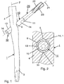
- a femoral fracture treatment device comprising an intramedullary nail 1, a sliding sleeve 10, a longitudinal bone fixation member 20 in the form of a hip screw or helix screw, and a blocking means 30.
- the intramedullary nail 1 has a central longitudinal axis 2, an insertable into the medullary canal of the femur front part 3, a rear part 4, and a rear part 4, obliquely to the longitudinal axis 2 piercing passage 5 with a non-circular cross section 6 (Fig. Fig. 2 to 4 ).
- the sliding sleeve 10 which can be passed through the non-circular passage 5 has a front end 11, a rear end 12, a central longitudinal bore 13, an outer lateral surface 14, an inner lateral surface 15 and a longitudinal axis 16.
- the longitudinal bone fixation element 20 in the form of a hip screw or helix screw has a longitudinal axis 21, a head portion 22 with fixation means 23, in the form of a multi-thread relatively high pitch thread, which are engageable with the femoral head in use, as well as a, coaxial with the sliding sleeve 10th insertable shaft 24.
- the outer lateral surface 14 of the sliding sleeve 10 has a non-circular cross-section 17, while the inner circumferential surface 15 of the sliding sleeve 10 only on a rear end 12 adjacent to its rear segment 36 has a non-circular cross section 38 and on a front segment 37 a round cross-section 18 having ( 10, 11 ).
- the round cross section 18 of the front segment 37 (FIG.
- the sliding sleeve 10 is secured by its non-circular cross-section 17 having outer lateral surface 14 in also a non-circular cross-section 6 having passage 5 of the intramedullary nail 1 against rotation.
- the non-circular cross-section 6 of the passage 5 is - as in Fig. 2 shown - formed substantially as a circle with two diametrically arranged, parallel to the longitudinal axis 16 of the sliding sleeve 10 grooves 7. Due to the complementary configuration of the outer lateral surface 14 of the sliding sleeve 10 with two elevations 35, the sliding sleeve 10 is secured in the passage 5 against rotation relative to the intramedullary nail 1. Thanks to this design, the intramedullary nail 1 can also be used with a conventional hip screw with a circular cylindrical shank, ie even without a sliding sleeve.
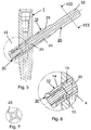
- Fig. 3 a variant of the non-circular cross section 6 of the passage 5 is shown.
- the circular cylindrical shaft 24 of the longitudinal bone fixation element 20 designed as a hip screw is rotatably mounted in the interior of the sliding sleeve 10 having a circular cylindrical inner lateral surface 15 in the front segment 37.
- the substantially a square, ie non-circular cross-section 17 having outer lateral surface 14 of the sliding sleeve 10 is, however, secured in the likewise a non-circular cross-section 6 having passage 5 of the intramedullary nail 1 against rotation.
- the non-circular cross-section 6 of the passage 5 is - as in Fig. 3 shown - also formed approximately square, but also has peripheral sections in the form of partial arcs. Thanks to this design, the intramedullary nail 1 can also with a conventional hip screw with circular cylindrical shaft be used, ie without sliding sleeve.
- a further variant of a non-circular cross section 6 of the passage 5 is shown, in which two small partial arcs and a larger partial arc are present. Accordingly, the non-circular cross section 17 of the outer circumferential surface 14 of the sliding sleeve 10 is formed.
- the blocking means 30 comprise a sleeve 60, which is displaceable parallel to the longitudinal axis 21 of the bone fixation element 20, and a clamping screw 70.
- the sleeve 60 is mounted so as to be axially displaceable in the longitudinal bore 13 at the rear end 12 of the sliding sleeve 10.
- the longitudinal bore 13 in the sliding sleeve 10 comprises two axially adjoining segments 36, 37, of which the front segment 37 has a round cross-section 18.
- the shaft 24 of the bone fixation element 20 is therefore at deblocked blocking means 30 (FIG. Fig. 9b ) rotatably supported about the longitudinal axis 16 of the sliding sleeve 10 in this.
- the fixing means 23 of the longitudinal bone fixation element 20 are formed as a four-barrel helical screw, wherein the thread has a pitch of about 120 mm.
- Fig. 9a and 9b are shown between the front end 62 of the sleeve 60 and the free end 27 of the shaft 24 with each other rotatably positively engageable engageable means 50 which are engageable by axial displacement of the sleeve 60 in engagement.
- the means 50 are engaged, ie blocked ( Fig. 9a )
- relative rotation between sleeve 60 and shank 24 about the longitudinal axis 21 of bone fixation member 20 is prevented
- deblocked means 50 FIG. Fig. 9b
- the means 50 are here designed as serrations 51, 52, wherein at the front end 62 of the sleeve 60 an annular first spur teeth 51 is arranged and the second spur gearing 52 is also arranged like an annular ring at the free end 27 of the shaft 24.
- the sleeve 60 has a central bore 65 with a coaxial, schraubares on the external thread 71 of the clamping screw 70 Internal thread 64 on. When tightening the clamping screw 70, the sleeve 60 is axially displaced against the free end 27 of the shank 24 until the two serrations 51, 52 are engaged at the front end 62 of the sleeve 60 and at the free end 27 of the shank 24 ( Fig. 9a ).
- the longitudinal bore 13 has in the region of its rear segment 36 a non-circular cross section 38 with also two flats 41 ( Fig. 11 ).
- blocked blocking means 30 (FIG. Fig. 9a ) is thus on the one hand, the bone fixation member 20 secured against rotation relative to the sliding sleeve 10 and on the other hand, the sliding sleeve 10 because of the non-circular cross-sections 6; 17 of passage 5 and outer surface 14 secured against rotation relative to the intramedullary nail 1.
- the clamping screw 70 is axially fixed and rotatably movable connected to the free end 27 of the shaft 24. As in the Fig. 9a and 9b shown this axial connection is realized by an engaging in an undercut 66 in the bore 25 in the shaft 24 bead 72 at the front end 73 of the clamping screw 70. Since the undercut 66 extends over the entire circumference of the bore 25, the rotation of the clamping screw 70 is not hindered relative to the shaft 24 about the longitudinal axis 21 of the bone fixation element 20.
- the clamping screw 70 is pierced coaxially and has at its rear end 74 means 75 for receiving a screwdriver (not shown).
- the sleeve 60 By the axial fixation of the clamping screw 70 on the shaft 24, the sleeve 60 is moved when tightening the clamping screw 70 against the free end 27 of the shaft 24 until the two spur teeth 51, 52 engage each other, while releasing the clamping screw 70, the sleeve 60 in the opposite direction is shifted until the two serrations 51, 52 are disengaged.
- the wall of the shaft 24 in the region of the free end 27 of the shaft 24 has a radial opening 42. And that way, that the clamping screw 70 with the bead 72 can be inserted laterally into the undercut 66.
Description
Die Erfindung bezieht sich auf eine Vorrichtung zur Behandlung von Frakturen des Femur gemäss dem Oberbegriff des Patentanspruchs 1.The invention relates to a device for treating fractures of the femur according to the preamble of
Es sind bereits Vorrichtungen bekannt, bei welchen eine Rotationssicherung des Femurkopfes mit einer einzigen Hüftschraube, d.h. einem longitudinalen Knochenfixationsmittel zu erreichen versucht wird. Aus der
Im weiteren ist aus der
Die obenstehende Diskussion des Standes der Technik erfolgt lediglich zur Erläuterung des Umfeldes der Erfindung und bedeutet nicht, dass der zitierte Stand der Technik zum Zeitpunkt dieser Anmeldung auch tatsächlich publiziert oder öffentlich bekannt war.The above discussion of the prior art is merely illustrative of the scope of the invention and does not imply that the cited prior art was actually published or publicly known at the time of this application.
Hier will die Erfindung Abhilfe schaffen. Der Erfindung liegt das Problem zugrunde, eine Vorrichtung zur Behandlung von Knochenfrakturen, insbesondere von proximalen Femurfrakturen zu schaffen, welche während der Implantation keine aufwendigen Justiervorgänge für den Operateur erfordert und einfach blockier- und deblockierbare, formschlüssige Rotationsblockierung zwischen dem longitudinalen Knochenfixationselement (z.B. der Hüftschraube) und dem Marknagel erlaubt.The invention aims to remedy this situation. The invention is based on the problem to provide a device for the treatment of bone fractures, in particular of proximal femur fractures, which requires no complicated adjustment operations for the surgeon during implantation and simply blockable and deblockable, positive rotational blocking between the longitudinal bone fixation element (eg the hip screw) and the intramedullary nail allowed.
Die Erfindung löst die gestellte Aufgabe mit einer Vorrichtung zur Behandlung von Frakturen des Femur, welche die Merkmale des Anspruchs 1 aufweist.The invention solves the stated object with a device for treating fractures of the femur, which has the features of
Die durch die Erfindung erreichten Vorteile sind im wesentlichen darin zu sehen, dass dank der erfindungsgemässen Vorrichtung
- das Knochenfixationselement relativ zum Marknagel mittels der Blockiermittel bezüglich Rotation um die Längsachse des Knochenfixationselementes wahlweise blockierbar oder deblockierbar ist;
- die Blockiermittel von lateral blockier- respektive deblockierbar sind;
- vor der Montage der Blockiermittel wegen der Rotierbarkeit der Gleithülse auf dem Schaft des Knochenfixationselementes das Einführen der Gleithülse nach der Implantation des Knochenfixationselementes ohne langes Justieren der Gleithülse möglich ist und somit die Operationsmethode vereinfacht und verkürzt wird;
- das laterale Gleiten des longitudinalen Knochenfixationselementes wird durch die Blockiermittel nicht limitiert;
- der vorzugsweise als Schraube oder Helixklinge ausgebildete Vorderteil des longitudinalen Knochenfixationselementes sich optimal in der Spongiosa des Femurkopfes verankern kann, weil der Schaft des longitudinalen Knochenfixationselementes in der ihn umschliessenden Hülse während dem Einbringen rotativ frei beweglich bleibt; und
- das longitudinale Knochenfixationselement beim Einbringen in den Femurkopf nicht speziell ausgerichtet werden muss und sich beim Einschlagen helixförmig in den Femurkopf drehen kann. Das longitudinale Knochenfixationselement ist in diesem Zeitpunkt noch nicht gegen Rotation gesichert. Der Chirurg kann somit noch Rotationskorrekturen des Femurkopfes vornehmen, bevor er die Rotation des longitudinalen Knochenfixationselementes in der Längsbohrung der Gleithülse blockiert.
- the bone fixation element is selectively blockable or deblockable relative to the intramedullary nail by means of the blocking means with respect to rotation about the longitudinal axis of the bone fixation element;
- the blocking agents are laterally blocking or deblockable;
- prior to assembly of the blocking means because of the rotatability of the sliding sleeve on the shank of the bone fixation element insertion of the sliding sleeve after implantation of the bone fixation element is possible without lengthy adjustment of the sliding sleeve and thus the operation method is simplified and shortened;
- the lateral sliding of the longitudinal bone fixation element is not limited by the blocking means;
- the front part of the longitudinal bone fixation element, preferably designed as a screw or helical blade, can be anchored optimally in the spongiosa of the femoral head, because the shaft of the longitudinal bone fixation element remains freely rotatable during insertion in the sleeve surrounding it. and
- the longitudinal bone fixation element does not need to be specially aligned when inserted into the femoral head and can helically rotate into the femoral head when impacted. The longitudinal bone fixation element is not yet secured against rotation at this time. The surgeon may thus still make rotational corrections of the femoral head before blocking the rotation of the longitudinal bone fixation element in the longitudinal bore of the sliding sleeve.
Weitere vorteilhafte Ausgestaltungen der Erfindung sind in den abhängigen Ansprüchen gekennzeichnet.Further advantageous embodiments of the invention are characterized in the dependent claims.
In einer bevorzugten Ausführungsform umfassen die Blockiermittel eine axialfest und rotativ bewegbar mit dem Schaft verbundene Spannschraube, mittels welcher eine in der Längsbohrung der Gleithülse axial verschiebbare und relativ zur Gleithülse rotativ feste Büchse. Vorzugsweise sind am vorderen Ende der Büchse und am freien Ende des Schaftes miteinander rotativ formschlüssig in Eingriff bringbare Mittel angeordnet.In a preferred embodiment, the blocking means comprise an axially fixed and rotatably movable connected to the shaft clamping screw, by means of which in the longitudinal bore of the sliding sleeve axially displaceable and relative to the sliding sleeve rotatably fixed sleeve. Preferably, at the front end of the sleeve and at the free end of the shaft with each other rotatably positively engageable engageable means are arranged.
In einer anderen Ausführungsform sind die Mittel am vorderen Ende der Büchse und am freien Ende des Schaftes als komplementäre Stirnverzahnungen ausgebildet. Damit sind die Vorteile erreichbar, dass
- die Stirnverzahnungen einen Eingriff bei verschiedenen Drehwinkeln zwischen dem Knochenfixationselement und der Gleithülse gestattet, so dass eine einfache Justierung zwischen Knochenfixationselement und intramedullärem Nagel während der Implantation ermöglicht wird; und
- durch die Stirnverzahnungen eine sichere Verdrehsicherung erreichbar ist.
- the serrations allow engagement at different angles of rotation between the bone fixation element and the sliding sleeve, allowing for easy adjustment between the bone fixation element and the intramedullary nail during implantation; and
- a secure rotation is achieved by the spur gears.
In wiederum einer anderen Ausführungsform weist die Spannschraube an ihrem vorderen Ende mit einem ringförmigen Wulst auf während der Schaft eine koaxiale Bohrung mit einem den Wulst aufnehmenden Hinterstich aufweist, so dass die Spannschraube rotierbar aber axial fest mit dem Schaft verbunden ist. Vorzugsweise umfassen die Bohrung und der Hinterstich eine radiale Öffnung, so dass die Spannschraube quer zur Längsachse des Knochenfixationselementes montierbar ist.In yet another embodiment, the tensioning screw has an annular bead at its forward end while the shaft has a coaxial bore with a bead receiving undercut so that the tensioning screw is rotatably but axially fixedly connected to the shaft. Preferably, the bore and the undercut comprise a radial opening, so that the tensioning screw can be mounted transversely to the longitudinal axis of the bone fixation element.
In einer weiteren Ausführungsform ist der unrunde Durchgang komplementär zum unrunden Querschnitt der äusseren Mantelfläche der Gleithülse ausgebildet, wobei beispielsweise der Querschnitt des Durchgangs so ausgestaltet ist, dass der unrunde Querschnitt des Durchgangs periphere Teilabschnitte in Form von Teilkreisbögen aufweist.In another embodiment, the non-circular passage is formed complementary to the non-circular cross section of the outer lateral surface of the sliding sleeve, wherein, for example, the cross section of the passage is designed so that the non-circular cross section of the passage has peripheral sections in the form of partial arcs.
Die Fixationsmittel des longitudinalen Knochenfixationselementes bestehen bevorzugt aus einer Helixklinge, vorzugsweise eine Doppelhelixklinge. Andere Ausgestaltungen der Fixationsmittel sind ein Schraubengewinde mit relativ geringer Steigung, ein Meissel, ein Nagel, ein T-Profil oder ein Doppel-T-Profil.The fixation means of the longitudinal bone fixation element preferably consist of a helix blade, preferably a double helix blade. Other embodiments of the fixation means are a screw thread with a relatively small pitch, a chisel, a nail, a T-profile or a double-T-profile.
In einer anderen Ausführungsform ist der Kopfteil des longitudinalen Knochenfixationselementes als mehrgängiges Gewinde, vorzugsweise als viergängiges Gewinde ausgebildet. Durch diese Ausgestaltung spielt die Positionierung de Knochenfixationselementes keine Rolle. Das Gewinde des Kopfteils kann dabei eine Steigung von mindestens 50 mm, vorzugsweise mindestens 80 mm aufweisen. Der Vorteil dieser relativ hohen Steigung liegt im höheren Widerstand gegen Rotation des Knochenfixationselementes. Zudem zerstört das als Helixklinge ausgebildete Knochenfixationselement weniger Knochensubstanz als eine konventionelle Hüftschraube mit relativ geringer Gewindesteigung. Der Knochen wird durch die Helixflächen der Helixklinge mehr kompaktiert als geschnitten.In another embodiment, the head part of the longitudinal bone fixation element is designed as a multi-start thread, preferably as a four-start thread. By this configuration, the positioning of the bone fixation element plays no role. The thread of the head part can have a pitch of at least 50 mm, preferably at least 80 mm. The advantage of this relatively high slope is the higher resistance to rotation of the bone fixation element. In addition, the trained as a helix bone bone fixation destroys less bone than a conventional hip screw with relatively low pitch. The bone is more compacted than cut by the helical surfaces of the helix blade.
Die Blockiermittel sind vorzugsweise derart dimensioniert, dass sie bezüglich des Durchgangs des intramedullären Nagels als axialer Stop wirken. Dieser Stop vermeidet eine zu weite Migration des Knochenfixationselementes nach medial.The blocking means are preferably dimensioned to act as an axial stop with respect to the passage of the intramedullary nail. This stop avoids too much migration of the bone fixation element medially.
In einer weiteren Ausführungsform ist das longitudinale Knochenfixationselement eine Hüftschraube.In a further embodiment, the longitudinal bone fixation element is a hip screw.
In wiederum einer weiteren Ausführungsform ist das longitudinale Knochenfixationselement eine Helix-Schraube.In yet another embodiment, the longitudinal bone fixation element is a helix screw.
Die Erfindung und Weiterbildungen der Erfindung werden im folgenden anhand der teilweise schematischen Darstellungen mehrerer Ausführungsbeispiele noch näher erläutert.The invention and further developments of the invention will be explained in more detail below with reference to the partially schematic representations of several embodiments.
Es zeigen:
-
Fig. 1 eine Seitenansicht durch die erfindungsgemässe Vorrichtung; -
Fig. 2 einen partiellen Schnitt durch einen Marknagel im Bereich seines schrägen Durchgangs mit eingesetzter Hüftschraube und Gleithülse; -
Fig. 3 einen partiellen Schnitt durch einen modifizierten Marknagel im Bereich seines schrägen Durchgangs mit eingesetzter Hüftschraube und Gleithülse; -
Fig. 4 einen partiellen Schnitt durch eine weitere Modifikation eines Marknagels im Bereich seines schrägen Durchgangs mit eingesetzter Hüftschraube und Gleithülse; -
Fig. 5 einen partiellen Schnitt durch die Vorrichtung gemässFig. 1 ; -
Fig. 6 einen vergrösserten Ausschnitt des Kreises VI inFig. 5 ; -
Fig. 7 einen Schnitt längs der Linie VII-VII inFig. 5 ; -
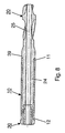
Fig. 8 einen Längsschnitt durch die Gleithülse mit darin vormontiertem Knochenfixationselement; -
Fig. 9a einen vergrösserten Ausschnitt des Kreises VI inFig. 5 mit blockierten Blockiermitteln; -
Fig. 9b einen vergrösserten Ausschnitt des Kreises VI inFig. 5 mit deblockierten Blockiermitteln; -
Fig. 10 einen Längsschnitt durch die inFig. 2 dargestellte Ausführungsform der Gleithülse; -
Fig. 11 eine Ansicht von hinten auf die inFig. 10 dargestellte Ausführungsform der Gleithülse; -
Fig. 12 einen Längsschnitt durch die inFig. 2 dargestellte Ausführungsform der Gleithülse mit eingeführtem Schaft des Knochenfixationselementes; und -
Fig. 13 einen Schnitt längs der Linie III-III inFig. 12 .
-
Fig. 1 a side view of the inventive device; -
Fig. 2 a partial section through an intramedullary nail in the region of its oblique passage with inserted hip screw and sliding sleeve; -
Fig. 3 a partial section through a modified intramedullary nail in the region of its oblique passage with inserted hip screw and sliding sleeve; -
Fig. 4 a partial section through a further modification of an intramedullary nail in the region of its oblique passage with inserted hip screw and sliding sleeve; -
Fig. 5 a partial section through the device according toFig. 1 ; -
Fig. 6 an enlarged section of the circle VI inFig. 5 ; -
Fig. 7 a section along the line VII-VII inFig. 5 ; -
Fig. 8 a longitudinal section through the sliding sleeve with the bone fixation element preassembled therein; -
Fig. 9a an enlarged section of the circle VI inFig. 5 with blocked blocking agents; -
Fig. 9b an enlarged section of the circle VI inFig. 5 with deblocked blocking agents; -
Fig. 10 a longitudinal section through the inFig. 2 illustrated embodiment of the sliding sleeve; -
Fig. 11 a view from behind on the inFig. 10 illustrated embodiment of the sliding sleeve; -
Fig. 12 a longitudinal section through the inFig. 2 illustrated embodiment of the sliding sleeve with inserted shaft of the bone fixation element; and -
Fig. 13 a section along the line III-III inFig. 12 ,
In den
Das longitudinale Knochenfixationselement 20 in Form einer Hüftschraube oder Helixschraube besitzt eine Längsachse 21, einen Kopfteil 22 mit Fixationsmitteln 23, in Form eines mehrgängigen Gewindes relativ hoher Steigung, die bei Benutzung mit dem Femurkopf in Eingriff bringbar sind, sowie einem, koaxial in die Gleithülse 10 einführbaren Schaft 24. Die äussere Mantelfläche 14 der Gleithülse 10 weist einen unrunden Querschnitt 17 auf, während die innere Mantelfläche 15 der Gleithülse 10 nur auf einem an ihr hinteres Ende 12 angrenzenden, hinteren Segment 36 einen unrunden Querschnitt 38 und auf einem vorderen Segment 37 einen runden Querschnitt 18 aufweist (
Wie in
In
In
Wie in den
Wie in den
Wie in
Wie in den
Bei blockierten Blockiermitteln 30 (
Die Spannschraube 70 ist axial fest und rotativ bewegbar mit dem freien Ende 27 des Schaftes 24 verbunden. Wie in den
Claims (15)
- Device for treating femoral fractures, withA) a intramedullary nail (1) with a central longitudinal axis (2), a front portion (3) insertable in the femoral medullary channel, a rear portion (4), and a passage (5) with a noncircular cross-section (6) penetrating the rear portion (4) transversally to the longitudinal axis (2);B) a sliding sleeve (10) movable through the noncircular passage (5) having a front end (11), a rear end (12), a central longitudinal bore (13), an outer peripheral surface (14), an inner peripheral surface (15) and a longitudinal axis (16);C) a longitudinal bone fixation element (20) with a longitudinal axis (21), a head portion (22) with fixating means (23) capable of being engaged with the femoral head upon use, and a shaft (24) capable of being coaxially inserted into the sliding sleeve (10); whereD) the outer peripheral surface (14) of the sliding sleeve (10) presents a noncircular cross-section (17) in at least one partial portion; andE) the inner peripheral surface (15) of the sliding sleeve (10) presents a noncircular cross-section (38) in at least one partial portion,
characterized in thatF) the shaft (24) is rotationally supported in the longitudinal bore (13) of the sliding sleeve (10), andG) locking means (30) are arranged at the free end (27) of the shaft (24), by which the shaft (24) can optionally be connected to the sliding sleeve (10) with a rotationally positive lock, so that the rotation of the longitudinal bone fixation element (20) relative to the sliding sleeve (10) can optionally be locked or unlocked. - Device according to claim 1, characterized in that the locking means (30) comprise an axially fastened and rotationally movable tightening screw (70) connected to the shaft (24) and a bushing (60) capable of being axially slid by the tightening screw (70) and rotationally fastened in the longitudinal bore (13) of the sliding sleeve (10).
- Device according to claim 2, characterized in that the bushing (60) has a front end (62) and the shaft (24) has a free end (27) and that means (50) capable of being engaged with each other with a rotationally positive lock are arranged at the front end (62) of the bushing (60) and at the free end (27) of the shaft (24).
- Device according to claim 3, characterized in that the means (50) comprise first radial serrations (51) at the front end (62) of the bushing (60) and second radial serrations (52) at the free end (27) of the shaft (24).
- Device according to one of the claims from 2 to 4, characterized in that the tightening screw (70) presents a front end (73) with a ring-shaped bulge (72) and that the shaft (24) presents a coaxial bore (25) with a recess (66) capable of rotationally receiving the bulge (72).
- Device according to claim 5, characterized in that the bore (25) and the recess (66) present a radial opening (42), so that the tightening screw (70) can be mounted transversally to the longitudinal axis (21) of the bone fixation element (20).
- Device according to one of the claims from 1 to 6, characterized in that the noncircular passage (5) is conformed complementary to the noncircular cross-section (17) of the outer peripheral surface (14) of the sliding sleeve.
- Device according to claim 7, characterized in that the noncircular cross-section (6) of the passage (5) presents peripheral partial portions in the form of partial circular arcs.
- Device according to claim 7 or 8, characterized in that the fixating means (23) of the longitudinal bone fixation element (20) are a helical blade, preferably a double helical blade.
- Device according to claim 7 or 8, characterized in that the fixating means (23) are a screw thread, a chisel, a nail, a T-profile or a double T-profile.
- Device according to one of the claims from 1 to 10, characterized in that the head portion (22) of the longitudinal bone fixation element (20) is conformed as a multiple thread, preferably a four-start thread.
- Device according to claim 11, characterized in that the thread of the head portion (22) presents a pitch of at least 50 mm, preferably of at least 80 mm.
- Device according to one of the claims from 7 to 11, characterized in that the locking means (30) act as an axial lock with reference to the passage (5).
- Device according to one of the claims from 1 to 13, characterized in that the longitudinal bone fixation element (20) is a hip screw.
- Device according to one of the claims from 1 to 13, characterized in that the longitudinal bone fixation element (20) is a helical screw.
Applications Claiming Priority (1)
| Application Number | Priority Date | Filing Date | Title |
|---|---|---|---|
| PCT/CH2003/000630 WO2005025435A1 (en) | 2003-09-18 | 2003-09-18 | Device for treating femoral fractures |
Publications (2)
| Publication Number | Publication Date |
|---|---|
| EP1663036A1 EP1663036A1 (en) | 2006-06-07 |
| EP1663036B1 true EP1663036B1 (en) | 2009-11-18 |
Family
ID=34280700
Family Applications (1)
| Application Number | Title | Priority Date | Filing Date |
|---|---|---|---|
| EP03818609A Expired - Lifetime EP1663036B1 (en) | 2003-09-18 | 2003-09-18 | Device for treating femoral fractures |
Country Status (15)
| Country | Link |
|---|---|
| US (1) | US7850690B2 (en) |
| EP (1) | EP1663036B1 (en) |
| JP (1) | JP4657104B2 (en) |
| KR (1) | KR101036055B1 (en) |
| CN (1) | CN100393287C (en) |
| AR (1) | AR045650A1 (en) |
| AT (1) | ATE448744T1 (en) |
| AU (1) | AU2003260232B2 (en) |
| BR (1) | BR0318488B1 (en) |
| CA (1) | CA2539488C (en) |
| DE (1) | DE50312145D1 (en) |
| ES (1) | ES2333320T3 (en) |
| NZ (1) | NZ545901A (en) |
| TW (1) | TWI335213B (en) |
| WO (1) | WO2005025435A1 (en) |
Cited By (1)
| Publication number | Priority date | Publication date | Assignee | Title |
|---|---|---|---|---|
| US9895177B2 (en) | 2016-01-15 | 2018-02-20 | ARTHREX, GmbH | Bone fixation device for treatment of femoral fractures |
Families Citing this family (52)
| Publication number | Priority date | Publication date | Assignee | Title |
|---|---|---|---|---|
| BRPI0418311B8 (en) * | 2004-02-23 | 2021-06-22 | Synthes Ag | bone screw |
| JP2009509660A (en) * | 2005-09-28 | 2009-03-12 | スミス アンド ネフュー インコーポレーテッド | Equipment for reducing femoral neck fractures |
| CA2648490C (en) * | 2006-04-06 | 2014-09-09 | Halifax Biomedical Inc. | Intramedullary rod with vent |
| US20080003255A1 (en) | 2006-05-10 | 2008-01-03 | Synthes (Usa) | Method for augmenting, reducing, and repairing bone with thermoplastic materials |
| US20090198237A1 (en) * | 2006-05-10 | 2009-08-06 | David Downey | Method for augmenting, reducing, and repairing bone with thermoplastic materials |
| DE102006032811A1 (en) * | 2006-06-21 | 2008-01-03 | Königsee Implantate und Instrumente zur Osteosynthese GmbH | Femoral head implant |
| US8579985B2 (en) * | 2006-12-07 | 2013-11-12 | Ihip Surgical, Llc | Method and apparatus for hip replacement |
| US8974540B2 (en) | 2006-12-07 | 2015-03-10 | Ihip Surgical, Llc | Method and apparatus for attachment in a modular hip replacement or fracture fixation device |
| CA2671523C (en) * | 2006-12-07 | 2013-02-12 | Anatol Podolsky | Method and apparatus for total hip replacement |
| US9308031B2 (en) | 2007-01-26 | 2016-04-12 | Biomet Manufacturing, Llc | Lockable intramedullary fixation device |
| US9320551B2 (en) | 2007-01-26 | 2016-04-26 | Biomet Manufacturing, Llc | Lockable intramedullary fixation device |
| US8177786B2 (en) * | 2007-03-30 | 2012-05-15 | Depuy Products, Inc. | Orthopaedic trauma hip screw assembly and associated method |
| EP2134278B1 (en) * | 2007-04-19 | 2012-08-22 | Stryker Trauma GmbH | Hip fracture device with barrel and end cap for load control |
| WO2008147975A1 (en) | 2007-05-25 | 2008-12-04 | Zimmer, Gmbh | Reinforced intramedullary nail |
| JP5628675B2 (en) * | 2007-09-27 | 2014-11-19 | シンセス ゲゼルシャフト ミット ベシュレンクテル ハフツング | Nail / plate combination |
| CN102176873A (en) | 2008-10-15 | 2011-09-07 | 捷迈有限公司 | Intramedullary nail |
| CN102355863B (en) | 2009-01-16 | 2014-09-17 | 卡波菲克斯整形有限公司 | Composite material bone implant |
| US8414582B2 (en) * | 2009-07-01 | 2013-04-09 | Synthes Usa, Llc | Intramedullary nail and protruding screw locking mechanism |
| CN202843761U (en) * | 2009-10-13 | 2013-04-03 | 捷迈有限责任公司 | Orthopedic nail and orthopedic nail system |
| KR101074446B1 (en) | 2009-11-19 | 2011-10-17 | 김정재 | apparatus for fixing a fracture part of femur |
| US9333090B2 (en) | 2010-01-13 | 2016-05-10 | Jcbd, Llc | Systems for and methods of fusing a sacroiliac joint |
| WO2014015309A1 (en) | 2012-07-20 | 2014-01-23 | Jcbd, Llc | Orthopedic anchoring system and methods |
| US9788961B2 (en) | 2010-01-13 | 2017-10-17 | Jcbd, Llc | Sacroiliac joint implant system |
| CA3002234C (en) | 2010-01-13 | 2020-07-28 | Jcbd, Llc | Sacroiliac joint fixation fusion system |
| US9381045B2 (en) | 2010-01-13 | 2016-07-05 | Jcbd, Llc | Sacroiliac joint implant and sacroiliac joint instrument for fusing a sacroiliac joint |
| US9421109B2 (en) | 2010-01-13 | 2016-08-23 | Jcbd, Llc | Systems and methods of fusing a sacroiliac joint |
| US10154867B2 (en) | 2010-06-07 | 2018-12-18 | Carbofix In Orthopedics Llc | Multi-layer composite material bone screw |
| CN105877829B (en) * | 2010-06-07 | 2018-06-22 | 卡波菲克斯整形有限公司 | Composite material bone implant |
| CA2825276C (en) * | 2011-01-21 | 2019-04-30 | Synthes Usa, Llc | Trochanteric femoral nail augmentable |
| US8709092B2 (en) | 2011-02-16 | 2014-04-29 | Genesis Medical Devices, LLC | Periprosthetic fracture management enhancements |
| ES2548045T3 (en) * | 2012-10-01 | 2015-10-13 | Stryker Trauma Gmbh | Intramedullary nail and implant system comprising said nail |
| US9717539B2 (en) | 2013-07-30 | 2017-08-01 | Jcbd, Llc | Implants, systems, and methods for fusing a sacroiliac joint |
| US9700356B2 (en) | 2013-07-30 | 2017-07-11 | Jcbd, Llc | Systems for and methods of fusing a sacroiliac joint |
| WO2014146018A1 (en) | 2013-03-15 | 2014-09-18 | Jcbd, Llc | Systems and methods for fusing a sacroiliac joint and anchoring an orthopedic appliance |
| US9826986B2 (en) | 2013-07-30 | 2017-11-28 | Jcbd, Llc | Systems for and methods of preparing a sacroiliac joint for fusion |
| US10245087B2 (en) | 2013-03-15 | 2019-04-02 | Jcbd, Llc | Systems and methods for fusing a sacroiliac joint and anchoring an orthopedic appliance |
| US9526542B2 (en) * | 2014-05-07 | 2016-12-27 | Acumed Llc | Hip fixation with load-controlled dynamization |
| US9433451B2 (en) | 2013-12-09 | 2016-09-06 | Acumed Llc | Hip fixation system with a compliant fixation element |
| US9463055B2 (en) | 2013-12-09 | 2016-10-11 | Acumed Llc | Plate-based compliant hip fixation system |
| EP3756596A1 (en) | 2013-12-09 | 2020-12-30 | Acumed LLC | Nail-based compliant hip fixation system |
| US10080596B2 (en) | 2013-12-09 | 2018-09-25 | Acumed Llc | Hip fixation with load-controlled dynamization |
| US9801546B2 (en) | 2014-05-27 | 2017-10-31 | Jcbd, Llc | Systems for and methods of diagnosing and treating a sacroiliac joint disorder |
| CN104146757A (en) * | 2014-07-14 | 2014-11-19 | 苏州瑞华医院有限公司 | Bone connecting device for treating femoral intertrochanteric fracture |
| CN105266875B (en) * | 2015-11-27 | 2017-06-09 | 广东工业大学 | Sliding and swing type orthopaedics positioning guide pin guider |
| US10617458B2 (en) | 2015-12-23 | 2020-04-14 | Carbofix In Orthopedics Llc | Multi-layer composite material bone screw |
| WO2018042595A1 (en) * | 2016-09-01 | 2018-03-08 | 株式会社オーミック | Thighbone fixing tool |
| EP3547944B1 (en) * | 2016-12-02 | 2021-10-27 | Stryker European Holdings I, LLC | Orthopedic locking screw |
| US10603055B2 (en) | 2017-09-15 | 2020-03-31 | Jcbd, Llc | Systems for and methods of preparing and fusing a sacroiliac joint |
| US11253304B2 (en) | 2018-01-03 | 2022-02-22 | Glw, Inc. | Hybrid cannulated orthopedic screws |
| EP3740145A1 (en) | 2018-01-15 | 2020-11-25 | GLW, Inc. | Hybrid intramedullary rods |
| EP3941373A1 (en) | 2019-03-18 | 2022-01-26 | GLW, Inc. | Hybrid bone plate |
| CN111281510A (en) * | 2020-02-27 | 2020-06-16 | 天津市威曼生物材料有限公司 | Combined anatomical intramedullary fixation device for proximal femur fracture |
Family Cites Families (31)
| Publication number | Priority date | Publication date | Assignee | Title |
|---|---|---|---|---|
| US4432358A (en) * | 1982-01-22 | 1984-02-21 | Fixel Irving E | Compression hip screw apparatus |
| US4733654A (en) * | 1986-05-29 | 1988-03-29 | Marino James F | Intramedullar nailing assembly |
| DE8701164U1 (en) * | 1987-01-24 | 1987-06-04 | Howmedica Gmbh, 2314 Schoenkirchen, De | |
| US5032125A (en) * | 1990-02-06 | 1991-07-16 | Smith & Nephew Richards Inc. | Intramedullary hip screw |
| GB9113578D0 (en) | 1991-06-24 | 1991-08-14 | Howmedica | Intramedullary intertrochanteric fracture fixation appliance |
| JPH09220235A (en) * | 1996-02-19 | 1997-08-26 | Bristol Mayers Sukuibu Kk | Osteosymphysis device |
| IT1287271B1 (en) * | 1996-04-05 | 1998-08-04 | Antonio Chemello | ENDOMIDOLLAR NAIL FOR THE OSTEOSYNTHESIS OF LONG BONE FRACTURES |
| US5741256A (en) * | 1997-01-13 | 1998-04-21 | Synthes (U.S.A.) | Helical osteosynthetic implant |
| DE19702201C1 (en) * | 1997-01-23 | 1998-08-06 | Aesculap Ag & Co Kg | Pin-shaped holding component for orthopaedic retention system |
| DE19750493A1 (en) * | 1997-11-14 | 1999-06-02 | Medos Medizintechnik Gmbh | Fracture stabilization implant and screw for use in surgery |
| US6248095B1 (en) * | 1998-02-23 | 2001-06-19 | Becton, Dickinson And Company | Low-cost medication delivery pen |
| US6139552A (en) * | 1998-05-13 | 2000-10-31 | K. K. Hollyx | Bone jointer and a bone jointer fixing tool |
| US6974290B2 (en) * | 1998-06-26 | 2005-12-13 | Dynamic Marketing Group Limited | Connecting assembly for joining two panels and mounting the joined panels on a support |
| DE19829228C1 (en) * | 1998-06-30 | 1999-10-28 | Aesculap Ag & Co Kg | Bone fracture fixture with locking-nail with through-hole |
| DE29823113U1 (en) * | 1998-12-28 | 2000-05-11 | Howmedica Gmbh | Femoral neck screw |
| US6783529B2 (en) * | 1999-04-09 | 2004-08-31 | Depuy Orthopaedics, Inc. | Non-metal inserts for bone support assembly |
| JP4336023B2 (en) * | 1999-05-12 | 2009-09-30 | 浩平 窪田 | Implant screw |
| US6221074B1 (en) * | 1999-06-10 | 2001-04-24 | Orthodyne, Inc. | Femoral intramedullary rod system |
| US6235031B1 (en) * | 2000-02-04 | 2001-05-22 | Encore Medical Corporation | Intramedullary fracture fixation device |
| US6645209B2 (en) * | 2000-04-04 | 2003-11-11 | Synthes (Usa) | Device for rotational stabilization of bone segments |
| US6533789B1 (en) * | 2000-04-04 | 2003-03-18 | Synthes (Usa) | Device for rotational stabilization of bone segments |
| JP4018327B2 (en) * | 2000-09-04 | 2007-12-05 | 株式会社ホムズ技研 | Osteosynthesis device |
| US6423033B1 (en) * | 2001-03-02 | 2002-07-23 | Jin-Chou Tsai | Safety hypodermic syringe |
| US6511481B2 (en) * | 2001-03-30 | 2003-01-28 | Triage Medical, Inc. | Method and apparatus for fixation of proximal femoral fractures |
| US6443954B1 (en) * | 2001-04-24 | 2002-09-03 | Dale G. Bramlet | Femoral nail intramedullary system |
| US6648889B2 (en) * | 2001-04-24 | 2003-11-18 | Dale G. Bramlet | Intramedullary hip nail with bifurcated lock |
| US6835197B2 (en) * | 2001-10-17 | 2004-12-28 | Christoph Andreas Roth | Bone fixation system |
| AU2002328243A1 (en) * | 2002-10-01 | 2004-04-23 | Synthes Ag Chur | Device for fixing bones |
| KR100953146B1 (en) * | 2002-10-29 | 2010-04-16 | 신세스 게엠바하 | Device for the treatment of fractures of the femur |
| EP1638473A2 (en) * | 2003-06-12 | 2006-03-29 | Disc-O-Tech Medical Technologies, Ltd. | Plate device |
| US7455673B2 (en) * | 2003-07-08 | 2008-11-25 | Yechiel Gotfried | Intramedullary nail system and method for fixation of a fractured bone |
-
2003
- 2003-09-18 DE DE50312145T patent/DE50312145D1/en not_active Expired - Lifetime
- 2003-09-18 EP EP03818609A patent/EP1663036B1/en not_active Expired - Lifetime
- 2003-09-18 KR KR1020067005464A patent/KR101036055B1/en active IP Right Grant
- 2003-09-18 NZ NZ545901A patent/NZ545901A/en unknown
- 2003-09-18 CN CNB038270889A patent/CN100393287C/en not_active Expired - Fee Related
- 2003-09-18 JP JP2005508841A patent/JP4657104B2/en not_active Expired - Fee Related
- 2003-09-18 BR BRPI0318488-9A patent/BR0318488B1/en active IP Right Grant
- 2003-09-18 ES ES03818609T patent/ES2333320T3/en not_active Expired - Lifetime
- 2003-09-18 CA CA2539488A patent/CA2539488C/en not_active Expired - Lifetime
- 2003-09-18 WO PCT/CH2003/000630 patent/WO2005025435A1/en active Application Filing
- 2003-09-18 AT AT03818609T patent/ATE448744T1/en active
- 2003-09-18 AU AU2003260232A patent/AU2003260232B2/en not_active Ceased
-
2004
- 2004-09-01 TW TW093126340A patent/TWI335213B/en not_active IP Right Cessation
- 2004-09-15 AR ARP040103289A patent/AR045650A1/en unknown
-
2006
- 2006-03-17 US US11/378,916 patent/US7850690B2/en active Active
Cited By (1)
| Publication number | Priority date | Publication date | Assignee | Title |
|---|---|---|---|---|
| US9895177B2 (en) | 2016-01-15 | 2018-02-20 | ARTHREX, GmbH | Bone fixation device for treatment of femoral fractures |
Also Published As
| Publication number | Publication date |
|---|---|
| DE50312145D1 (en) | 2009-12-31 |
| KR101036055B1 (en) | 2011-05-19 |
| CA2539488C (en) | 2011-11-08 |
| ATE448744T1 (en) | 2009-12-15 |
| AU2003260232B2 (en) | 2009-04-09 |
| TW200513229A (en) | 2005-04-16 |
| US20060241604A1 (en) | 2006-10-26 |
| NZ545901A (en) | 2007-11-30 |
| CA2539488A1 (en) | 2005-03-24 |
| CN100393287C (en) | 2008-06-11 |
| WO2005025435A1 (en) | 2005-03-24 |
| JP2007506454A (en) | 2007-03-22 |
| TWI335213B (en) | 2011-01-01 |
| JP4657104B2 (en) | 2011-03-23 |
| KR20060097749A (en) | 2006-09-15 |
| ES2333320T3 (en) | 2010-02-19 |
| CN1838922A (en) | 2006-09-27 |
| BR0318488B1 (en) | 2012-05-02 |
| EP1663036A1 (en) | 2006-06-07 |
| US7850690B2 (en) | 2010-12-14 |
| AR045650A1 (en) | 2005-11-02 |
| AU2003260232A1 (en) | 2005-04-06 |
| BR0318488A (en) | 2006-09-12 |
Similar Documents
| Publication | Publication Date | Title |
|---|---|---|
| EP1663036B1 (en) | Device for treating femoral fractures | |
| EP1558159B1 (en) | Device for the treatment of fractures of the femur | |
| EP2263584B1 (en) | Intramedullary nail with locking screw | |
| DE10246386B4 (en) | Bone screw, bone fixation device and retaining element | |
| DE10157814B4 (en) | Closure device for securing a rod-shaped element in a holding element connected to a shaft | |
| EP1681024B1 (en) | Bone anchor element | |
| DE10157969C1 (en) | Element used in spinal and accident surgery comprises a shaft joined to a holding element having a U-shaped recess with two free arms having an internal thread with flanks lying at right angles to the central axis of the holding element | |
| DE3541597C2 (en) | ||
| EP1761182B1 (en) | Surgical nail | |
| DE102006005667B4 (en) | Dental implant, screw plug and abutment for such a dental implant | |
| EP2421455B1 (en) | Fastening apparatus for surgical retaining systems | |
| WO1999062418A1 (en) | Surgical blind rivets with closing elements | |
| WO2004086990A1 (en) | Housing for a locking element and locking element | |
| EP0682917B1 (en) | Screwdriver for a screw consisting of a bolt and a nut adapted to be screwed thereon | |
| DE2724307A1 (en) | DEVICE FOR SUPPORTING BONE TISSUE | |
| DE2906068C2 (en) | Device for fastening pieces of bone | |
| EP1720473B1 (en) | Bone fixation means | |
| WO2007023101A1 (en) | Proximal femur nail | |
| EP3742993B1 (en) | Intervertebral screw | |
| EP2768401B1 (en) | Mtv implantation set | |
| WO2004000144A1 (en) | Bone screw comprising a tangential cutting edge | |
| WO2016083355A1 (en) | Securing element | |
| DE202022104343U1 (en) | Device for actuating an intramedullary nail, comprising a threaded element for connecting an intramedullary nail | |
| DE102022119169A1 (en) | Device for actuating an intramedullary nail, comprising a threaded element for connecting an intramedullary nail | |
| WO2024027879A1 (en) | Device for manipulating an intramedullary rod, comprising an adapter piece, set for providing such a device, adapter piece, and adapter set |
Legal Events
| Date | Code | Title | Description |
|---|---|---|---|
| PUAI | Public reference made under article 153(3) epc to a published international application that has entered the european phase |
Free format text: ORIGINAL CODE: 0009012 |
|
| 17P | Request for examination filed |
Effective date: 20060222 |
|
| AK | Designated contracting states |
Kind code of ref document: A1 Designated state(s): AT BE BG CH CY CZ DE DK EE ES FI FR GB GR HU IE IT LI LU MC NL PT RO SE SI SK TR |
|
| DAX | Request for extension of the european patent (deleted) | ||
| GRAP | Despatch of communication of intention to grant a patent |
Free format text: ORIGINAL CODE: EPIDOSNIGR1 |
|
| GRAS | Grant fee paid |
Free format text: ORIGINAL CODE: EPIDOSNIGR3 |
|
| GRAA | (expected) grant |
Free format text: ORIGINAL CODE: 0009210 |
|
| AK | Designated contracting states |
Kind code of ref document: B1 Designated state(s): AT BE BG CH CY CZ DE DK EE ES FI FR GB GR HU IE IT LI LU MC NL PT RO SE SI SK TR |
|
| REG | Reference to a national code |
Ref country code: GB Ref legal event code: FG4D Free format text: NOT ENGLISH |
|
| REG | Reference to a national code |
Ref country code: CH Ref legal event code: NV Representative=s name: DR. LUSUARDI AG Ref country code: CH Ref legal event code: EP |
|
| REG | Reference to a national code |
Ref country code: IE Ref legal event code: FG4D |
|
| REG | Reference to a national code |
Ref country code: SE Ref legal event code: TRGR |
|
| REF | Corresponds to: |
Ref document number: 50312145 Country of ref document: DE Date of ref document: 20091231 Kind code of ref document: P |
|
| REG | Reference to a national code |
Ref country code: ES Ref legal event code: FG2A Ref document number: 2333320 Country of ref document: ES Kind code of ref document: T3 |
|
| REG | Reference to a national code |
Ref country code: NL Ref legal event code: VDEP Effective date: 20091118 |
|
| PG25 | Lapsed in a contracting state [announced via postgrant information from national office to epo] |
Ref country code: FI Free format text: LAPSE BECAUSE OF FAILURE TO SUBMIT A TRANSLATION OF THE DESCRIPTION OR TO PAY THE FEE WITHIN THE PRESCRIBED TIME-LIMIT Effective date: 20091118 Ref country code: PT Free format text: LAPSE BECAUSE OF FAILURE TO SUBMIT A TRANSLATION OF THE DESCRIPTION OR TO PAY THE FEE WITHIN THE PRESCRIBED TIME-LIMIT Effective date: 20100318 |
|
| PG25 | Lapsed in a contracting state [announced via postgrant information from national office to epo] |
Ref country code: CY Free format text: LAPSE BECAUSE OF FAILURE TO SUBMIT A TRANSLATION OF THE DESCRIPTION OR TO PAY THE FEE WITHIN THE PRESCRIBED TIME-LIMIT Effective date: 20091118 Ref country code: SI Free format text: LAPSE BECAUSE OF FAILURE TO SUBMIT A TRANSLATION OF THE DESCRIPTION OR TO PAY THE FEE WITHIN THE PRESCRIBED TIME-LIMIT Effective date: 20091118 |
|
| REG | Reference to a national code |
Ref country code: IE Ref legal event code: FD4D |
|
| PG25 | Lapsed in a contracting state [announced via postgrant information from national office to epo] |
Ref country code: RO Free format text: LAPSE BECAUSE OF FAILURE TO SUBMIT A TRANSLATION OF THE DESCRIPTION OR TO PAY THE FEE WITHIN THE PRESCRIBED TIME-LIMIT Effective date: 20091118 Ref country code: DK Free format text: LAPSE BECAUSE OF FAILURE TO SUBMIT A TRANSLATION OF THE DESCRIPTION OR TO PAY THE FEE WITHIN THE PRESCRIBED TIME-LIMIT Effective date: 20091118 Ref country code: IE Free format text: LAPSE BECAUSE OF FAILURE TO SUBMIT A TRANSLATION OF THE DESCRIPTION OR TO PAY THE FEE WITHIN THE PRESCRIBED TIME-LIMIT Effective date: 20091118 Ref country code: BG Free format text: LAPSE BECAUSE OF FAILURE TO SUBMIT A TRANSLATION OF THE DESCRIPTION OR TO PAY THE FEE WITHIN THE PRESCRIBED TIME-LIMIT Effective date: 20100218 Ref country code: EE Free format text: LAPSE BECAUSE OF FAILURE TO SUBMIT A TRANSLATION OF THE DESCRIPTION OR TO PAY THE FEE WITHIN THE PRESCRIBED TIME-LIMIT Effective date: 20091118 Ref country code: NL Free format text: LAPSE BECAUSE OF FAILURE TO SUBMIT A TRANSLATION OF THE DESCRIPTION OR TO PAY THE FEE WITHIN THE PRESCRIBED TIME-LIMIT Effective date: 20091118 |
|
| REG | Reference to a national code |
Ref country code: HU Ref legal event code: AG4A Ref document number: E007835 Country of ref document: HU |
|
| PG25 | Lapsed in a contracting state [announced via postgrant information from national office to epo] |
Ref country code: CZ Free format text: LAPSE BECAUSE OF FAILURE TO SUBMIT A TRANSLATION OF THE DESCRIPTION OR TO PAY THE FEE WITHIN THE PRESCRIBED TIME-LIMIT Effective date: 20091118 Ref country code: SK Free format text: LAPSE BECAUSE OF FAILURE TO SUBMIT A TRANSLATION OF THE DESCRIPTION OR TO PAY THE FEE WITHIN THE PRESCRIBED TIME-LIMIT Effective date: 20091118 |
|
| PLBE | No opposition filed within time limit |
Free format text: ORIGINAL CODE: 0009261 |
|
| STAA | Information on the status of an ep patent application or granted ep patent |
Free format text: STATUS: NO OPPOSITION FILED WITHIN TIME LIMIT |
|
| 26N | No opposition filed |
Effective date: 20100819 |
|
| PG25 | Lapsed in a contracting state [announced via postgrant information from national office to epo] |
Ref country code: GR Free format text: LAPSE BECAUSE OF FAILURE TO SUBMIT A TRANSLATION OF THE DESCRIPTION OR TO PAY THE FEE WITHIN THE PRESCRIBED TIME-LIMIT Effective date: 20100219 |
|
| BERE | Be: lapsed |
Owner name: SYNTHES GMBH Effective date: 20100930 |
|
| PG25 | Lapsed in a contracting state [announced via postgrant information from national office to epo] |
Ref country code: MC Free format text: LAPSE BECAUSE OF NON-PAYMENT OF DUE FEES Effective date: 20100930 |
|
| REG | Reference to a national code |
Ref country code: SE Ref legal event code: EUG |
|
| PG25 | Lapsed in a contracting state [announced via postgrant information from national office to epo] |
Ref country code: BE Free format text: LAPSE BECAUSE OF NON-PAYMENT OF DUE FEES Effective date: 20100930 |
|
| PG25 | Lapsed in a contracting state [announced via postgrant information from national office to epo] |
Ref country code: SE Free format text: LAPSE BECAUSE OF NON-PAYMENT OF DUE FEES Effective date: 20100919 Ref country code: LU Free format text: LAPSE BECAUSE OF NON-PAYMENT OF DUE FEES Effective date: 20100918 |
|
| PG25 | Lapsed in a contracting state [announced via postgrant information from national office to epo] |
Ref country code: TR Free format text: LAPSE BECAUSE OF FAILURE TO SUBMIT A TRANSLATION OF THE DESCRIPTION OR TO PAY THE FEE WITHIN THE PRESCRIBED TIME-LIMIT Effective date: 20091118 |
|
| REG | Reference to a national code |
Ref country code: FR Ref legal event code: PLFP Year of fee payment: 14 |
|
| REG | Reference to a national code |
Ref country code: FR Ref legal event code: PLFP Year of fee payment: 15 |
|
| REG | Reference to a national code |
Ref country code: FR Ref legal event code: PLFP Year of fee payment: 16 |
|
| PGFP | Annual fee paid to national office [announced via postgrant information from national office to epo] |
Ref country code: IT Payment date: 20210811 Year of fee payment: 19 Ref country code: CH Payment date: 20210916 Year of fee payment: 19 Ref country code: AT Payment date: 20210825 Year of fee payment: 19 Ref country code: FR Payment date: 20210812 Year of fee payment: 19 |
|
| PGFP | Annual fee paid to national office [announced via postgrant information from national office to epo] |
Ref country code: GB Payment date: 20210811 Year of fee payment: 19 Ref country code: HU Payment date: 20210815 Year of fee payment: 19 Ref country code: DE Payment date: 20210810 Year of fee payment: 19 |
|
| PGFP | Annual fee paid to national office [announced via postgrant information from national office to epo] |
Ref country code: ES Payment date: 20211006 Year of fee payment: 19 |
|
| REG | Reference to a national code |
Ref country code: DE Ref legal event code: R119 Ref document number: 50312145 Country of ref document: DE |
|
| REG | Reference to a national code |
Ref country code: CH Ref legal event code: PL |
|
| REG | Reference to a national code |
Ref country code: AT Ref legal event code: MM01 Ref document number: 448744 Country of ref document: AT Kind code of ref document: T Effective date: 20220918 |
|
| GBPC | Gb: european patent ceased through non-payment of renewal fee |
Effective date: 20220918 |
|
| PG25 | Lapsed in a contracting state [announced via postgrant information from national office to epo] |
Ref country code: LI Free format text: LAPSE BECAUSE OF NON-PAYMENT OF DUE FEES Effective date: 20220930 Ref country code: FR Free format text: LAPSE BECAUSE OF NON-PAYMENT OF DUE FEES Effective date: 20220930 Ref country code: DE Free format text: LAPSE BECAUSE OF NON-PAYMENT OF DUE FEES Effective date: 20230401 Ref country code: CH Free format text: LAPSE BECAUSE OF NON-PAYMENT OF DUE FEES Effective date: 20220930 Ref country code: AT Free format text: LAPSE BECAUSE OF NON-PAYMENT OF DUE FEES Effective date: 20220918 |
|
| REG | Reference to a national code |
Ref country code: ES Ref legal event code: FD2A Effective date: 20231027 |
|
| PG25 | Lapsed in a contracting state [announced via postgrant information from national office to epo] |
Ref country code: IT Free format text: LAPSE BECAUSE OF NON-PAYMENT OF DUE FEES Effective date: 20220918 Ref country code: GB Free format text: LAPSE BECAUSE OF NON-PAYMENT OF DUE FEES Effective date: 20220918 |
|
| PG25 | Lapsed in a contracting state [announced via postgrant information from national office to epo] |
Ref country code: ES Free format text: LAPSE BECAUSE OF NON-PAYMENT OF DUE FEES Effective date: 20220919 |
|
| PG25 | Lapsed in a contracting state [announced via postgrant information from national office to epo] |
Ref country code: ES Free format text: LAPSE BECAUSE OF NON-PAYMENT OF DUE FEES Effective date: 20220919 |